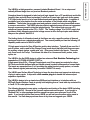
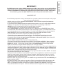
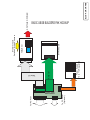
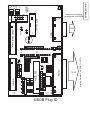
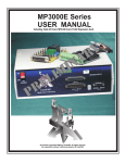
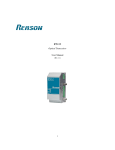
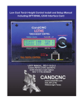
1
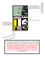
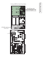
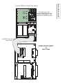
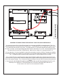
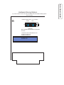
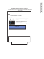
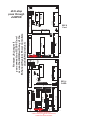
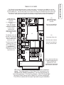
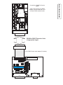
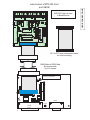
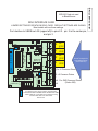
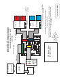
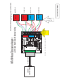
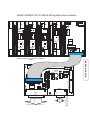
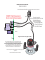
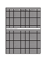
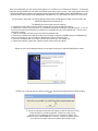
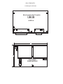
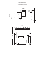
REV2 12/15/2008
10/15/2008
USER MANUAL REV3
Covers UBOB, UBOB Builders Kit.
For ver 4
1 and 6
2 of UBOB
Contents:
! Overview/Features
! Quick Start
! Overlay and parts locations
! Graphical schematic of common connections
! Step by step hookup and inital testing
! Final setup and calibration
!
INTRODUCTION
UBOB - The Ultimate Breakout Board
J
A breakout board is designed to take low level logic signals from a PC parallel port and buffer
(amplify) them and shift them to standard 5 volts from a lower logic type such as the newer
3.3V logic levels found in a lot of new Motherboards and laptop parallel ports. In addition it
provides a level of protection from the noise and spikes of the outside world using Opto
Isolation. That breaks the grounds apart and prevents noise from being transmitted across
a common connection. The UBOB uses two distinct regulated power sources not connected
through a common ground to drive the isolated inputs. The internal logic runs on a PC
referenced (same ground as the PC) + 5VDC. The “floating voltage” is a 12VDC supply that
provides a totally separate ground and voltage source to drive the input optos and external
relays on the optional Table I/O II
The limiting factor of all breakout cards is that there are only a specific number of discreet
inputs and outputs on a standard parallel port. The normal parallel port has the following I/O
capability under control of MACH or EMC:
12 high speed outputs for Step & Direction and/or relay interface. Typically 8 are used for 4
axis of motion, one is used for the Charge Pump (more about that later) and three are open
for auxillary outputs (relays, enable pins, etc). Even more limited is the inputs. There are
only 5 and one is for E-stop. That leaves the other 4 for Homes and limits, probes, index
inputs, etc.
The UBOB is the first BOB design to utilized an advanced Port Stretcher Technology that
expands the I/O FROM A SINGLE PORT to:
9 high speed (step & Dir + Charge Pump)outputs, and 8 low speed aux outputs for relays.
All 8 lines are double buffered and can handle several hundred milliamperes of current each.
The inputs are expanded from 5 to 9 providing the added inputs to setup probes, or handle
other external signals (external rotary encoders CANNOT be used).
The UBOB uses Surface Mount Techology to keep the size down and supports a wide array
of plug-in option cards. It ships with a free custom plug-in to handle the advanced port
expansion capabilities
The UBOB is design to be a stand alone BOB and port interface or to interface with our
EZPlug© Gecko Interface Cards to quickly build anything from a 3 axis table top router/mill to
a 5 axis 5 X10 router/plasma table.
The following document covers setup, configuration and testing of the basic UBOB including
the setup in MACH3. Several of the common option cards are covered. If you bought a
“Builders Pak” or other package deal this manual can serve as a reference for all of the
cards. If you bought just the bare bones UBOB you will not have the other option cards in
this manual. You can always purchase them at any time and upgrade your UBOB.
INTRODUCTION
The UBOB is a third generation, powered, isolated Breakout Board. It is a unique and
radically different deign from our previous Breakout products.
The UBOB requires the version of MACH shipped on the CD (or later versions we can certify) AND our
MACH specific plug-in (UBOB.dll). IT WILL NOT WORK WITH OLDER MACH VERSIONS THAN 3.041
and the PLUG-IN MUST be installed and configured for the outputs to work correctly. Please take a
few minutes to go down the QUIK START List to make sure you have the basics in place.
QUIK START LIST.
Do the following setup with a motor(s) disconnected from your table (or drive belt removed) to confirm proper
setup and motor rotation/direction
! MACH version from CD (or download) installed/updated. Version 3.042.020 required (See Addendum
section for software step-by-step)
! If you have a version of MACH running with another Breakout make a copy of the (entire) MACH folder as
a backup. You can open it and retrieve the motor tuning and other custom settings to save time.
! INSTALL from CD or Download Run INSTALL and files show up in MACH
! Use the MP3000-Install. That will setup the UBOB and all the cards.
! Open Config Plugins from MACH3 menu and verify CCC_UBOB plug-in is ENABLED (Green Check)
! For Builders Pak and modular products see the section on hooking up power. The UBOB needs a source
of +5 and (separate) source of +12 both at 500ma. The Quad Power Module (Only one side populated for
UBOB applications) uses a single ribbon cable interface to power the UBOB and Table I/O cards.
! Power up UBOB and connect to computer (PC) parallel port one (Port1)
! Serial port interface is not required for basic operation. On UBOB ONLY installs there is no serial
communications. The UBOB serial is a pass-through for other CandCNC devices/expansion cards.
! Connect the Table I/O card and make sure the EPO jumper on the card is in place. (also sse the MTA
card and notes about the EPO jumper there)
! Get the UBOB installed WITHOUT Homes or Limits to begin with.
! The proper Ports and Pins configuration for the UBOB is in the MP3000 profile(XML). When you select
that profile in the MACH loader you should only have to make changes in the Motor Tuning and Motor
Outputs (Dir change). The only other changes might be in Homing/Limits as to the homing direction.
! Make sure in MACH running the MP3000 Profile you can come out of RESET
! Turn all the power off and connect up the Axis I/O cable to the MTA100 Card. That card is designed to be a
multi-purpose breakout for direct (screw terminal) connections to motor drives that use Step & Direction and
a Common connection, or by using ribbon cables, connects directly to our EZPLug Stepper or EZPlug Servo
interface cards. Sections of this manual cover the interconnects.
! The circuitry in the UBOB requires that the Charge Pump signal from MACH be OFF in RESET The default
setup profile has that set right...do not change it.
! Once you have the motor drives connected and DC power to them (supplied by a separate DC motor power
supply). the motors should “lock up” when DC power is supplied. Start with just one motor (X). Confirm
lockup and then with the UBOB powered up and the DC power to the motor drives jog the X axis from the
keyboard using the left and right arrow keys.
!Confirm the other axis jogs by moving the X motor Make sure you turn off DC to the drives BEFORE you
plug or unplug a motor!
!The Inputs for Homes, limits, probes, etc are via the Table IO card and into the Table I/O connector to the
UBOB. There are also two relays on the Table I/O card that are controlled by Output1 and Output2 in
MACH. By default those outputs are setup to be triggered by Spindle on/off (M03/M05 G-code commands)
and by M06 and M08 for the output2. There are also buttons on the Program Run Screen we supply.
QUICK START
IMPORTANT!!
UBOB
To PC Serial
(Optional)
TO PC Port1
Power Supply
+5 & +12 Regulated
AXIS I/O
Table I/O
MTA100 Card
TABLE I/O
Multiple Inputs
Switches, probes, sensors
BLOCK DIAGRAMS
SWITCHED POWER
BASIC UBOB BUILDERS PAK HOOKUP
1
PPORT1
1
Q2
Q4
Axis Slave
PLUG
Q9
AXIS I/O
RN2
Q5
U5
C1
UBOB Plug ID
U8
CP
U3
U2
C5
SERIAL
J4
POWER
2
Serial port is optional
not used with just UBOB
TO PC
TO PC
REV4
27
UBOB
FLOAT-GND
+12
PCGND
+5
CONNECTOR ID
SKT
J29
FEATURE CONN
PC+5
PCGND
10
Primary Parallel Port (PORT1 /LPT1)
Q3
1
1
1
Q1
PORT2 INTERCONNECT
1
1
1
TABLE I/O
1
J2
AXIS I/O
1
J6
J7
J65
UBOB REV 6 Plug ID
PLUG
AXIS I/O
TO PC
J56
J1
+
Primary Parallel Port (PORT1 /LPT1)
14
1
PPORT1
J63
1
1
TABLE I/O
1
CP
U3
C1
1
U2
C5
SERIAL
C12
REV6
FEATURE
CONN
SKT
J29
UBOB
POWER
PORT2 INTERCONNECT
1
J57
1
1
J6
1
1
1
1
J2
J8
J7
TO PC
FLOAT-GND
+12
PCGND
PC+5
CONNECTOR ID
Serial port is optional
not used with just UBOB
C7
C8
R2
R1
5VDC
26
27
C4
C5
C10
C3
25
12VDC
D17
G-12V
REG4
12V Reg
REG3
DANGER AREA on
TOP AND BOTTOM OF
CARD IN YELLOW AREA
HIGH VOLTAGE!
FLT 12
All other areas are low voltage
C1
R8
D14
-
C6
~
5V Reg
D3
D19
R3
~
10
9
C11
J13
+
2
1
Quad power
1
J2
PWR X-CONNECT
F1
AC INPUT 105 - 125VAC 60HZ
The Quad output Power Module is designed to furnish a source of 5V regulated
and a separate (floating) source of 12V regulated. It cross connects to the UBOB
via a single 10 pin ribbon cable. A source of 120VAC AC is needed. The hookup
if the AC into the Power Module is the responsibility of the user/builder. AC
volts over about 65 VAC is dangerous and can case seroius injury or death.
NEVER MAKE A CONNECTION WITH THE AC CORD PLUGGED IN. If you
cannot safely hook two wires up to wall current DO NOT ATTEMPT THE
PROCESS, SEEK PROFESSIONAL HELP. There is an area on the card that
is at high voltage. DO NOT PICKUP OR MOVE THE CARD with the
AC PLUGGED IN!
UBOB CONNECTIONS
+5
+12
J8
J5
J7
GND
Second Power supply
for use with BladeRunner and
EZPLUG G250 installs. Not
populated on UBOB only units
Q2
1
PPORT1
C8
SIP3
26
1
AXIS I/O
J6
Q1
Q4
AXIS I/O
Q3
Q5
RN2
U7
Q9
J65
R2
J56
U5
U6
FAN
R9
U15
RN1
SIP1
J63
D17
REV1
C5
PCGND
J60
Q6
SERIAL
Q7
Q8
UBOB
PC+5
U10
R63
+12
SKT
J29
D8
25
J4
27
F1
D19
C6
D3
~
+
J13
-
~
24
Quad power
R8
C1
FLT 12
D14
U8
CP
U3
U2
U11
D4
C3
PORT2 INTERCONNECT
R54
D18
D14
Axis Slave
R37
TABLE I/O
FEATURE CONN
D7
C2
10
9
5V Reg
1
D6
C11
R3
J5
10
9
2
1
2
1
SIP2
PWR X-CONNECT
24
C10
C5
12V Reg
J2
POWER
C4
C3
10 PIN IDC cable for power
interconnect
26
27
25
G-12V
D17
12VDC
J57
1
J3
C8
C7
R1
R2
+5
+12
GND
5VDC
R6
Second Power supply
for use with BladeRunner and
EZPLUG G250 installs. Not
populated on UBOB only units
REG3
PWR X-CONNECT
REG4
UBOB CONNECTIONS
J8
J5
J7
Powering UBOB from Quad Power Module
1
Second Power supply
for use with BladeRunner and
EZPLUG G250 installs. Not
populated on UBOB only units
C7
C8
R2
R1
5VDC
26
27
C3
25
12VDC
D17
G-12V
REG4
C4
C5
C10
12V Reg
FLT 12
REG3
C1
R8
D14
F1
FLOAT-GND
D19
C6
PWR X-CONNECT
+
~
D3
-
~
24
J13
1
1
1
SKT
J29
+12
5V Reg
PC+5
R3
PCGND
10
9
Quad power
1
2
1
C11
1
J2
J7
CP
C1
1
J57
1
U2
U3
C5
C12
SERIAL
FEATURE
CONN
POWER
REV6
PORT2 INTERCONNECT
1
1
UBOB
1
J2
10 PIN IDC cable for power
interconnect
PWR X-CONNECT
J1
J8
J63
14
1
PPORT1
J65
AXIS I/O
PLUG
J56
+
1
1
TABLE I/O
Power Cross Connect
to
REV 6 card
UBOB CONNECTIONS
J8
+5
+12
GND
J7
J5
Powering UBOB from Quad Power Module
J6
J2
1
1
1
UBOB
1
U2
PC+5
PCGND
1
PORT2 INTERCONNECT
J7
1
J57
TABLE I/O
+12
FLOAT-GND
REV6
C5
1
J65
J63
POWER
FEATURE
CONN
J8
U3
+
PPORT1
C1
SERIAL
J1
1
1
14
PLUG
CP
SKT
J29
UBOB CONNECTIONS
C12
1
J56
1
J6
1
AXIS I/O
POWERING THE UBOB FROM OTHER SOURCES THAN THE QUAD POWER MODULE
If you do not have the Dual or Quad Power Module you can power the UBOB from several sources. The +5 is
referenced (shares the same ground return) with the PC +5. The parallel port on a PC DOES NOT HAVE a source
of +5 other than leak pull-ups on logic lines. The USB part has a +5 line and the internal power supply of most
PC’s has a +5 output. You can get tap plugs that allow access to the internal +5 on a PC. The wires used to power
hard drives and CD drives has +5 (Red Blk pair). Make sure the voltage is +5 regulated and NOT +12.
You can supply the +5 from any regulated +5 power that can handle a minimum of 250ma. Examples are wallplug
transformers, Desktop power supplies (for some laptops, etc) and open board power supplies from hobby sources.
The ..1 solderless (crimp on) terminals are marked with PC+5 and PCGND for the 5 volt input.
The +12 input HAS to be a separate power supply rated at 500ma or higher with a separate ground return (not
connected to the +5 ground return) Most dual output power supplies share the same ground connection so will not
work for the required voltages. The +12 drives the inputs of the Opto’s (from the Table I/O card) and also drives the
relays.
IF YOU DO NOT USE SEPARATE POWER SOURCES WITH THE 12V RETURN COMMON WITH THE +5 (PC
GROUND) YOU LOOSE ALL THE ADVANTAGES OF THE INPUT ISOLATION AND THE OPTO’s
Do not use the +12 in the PC as it is connected to PCGND.
If you do not have or use a 5th motor and driver then the Hardware Slaving option
does not matter
Hardware Slave shown in “X” Position
2
STEP
4 6
2
1
3
5
1
DIR
4 6
J63
3
5
Axis Slave
Both OPTION BLOCKS MUST be jumpered
the same.
1-2 External drive FROM PORT2 card
3-4 Slave 5th Axis to X
5-6 Slave 5th Axis to Y
AXIS I/O
1
UBOB CONNECTIONS
Hardware Slaving Options.
If you do not have or use a 5th motor and driver then the Hardware Slaving option
does not matter
Both OPTION BLOCKS MUST be jumpered
the same.
1-2 External drive FROM PORT2 card
3-4 Slave 5th Axis to X
5-6 Slave 5th Axis to Y
1
2
1
J63
2
4
3
5
6
5
6
DIR
Axis Slave
STEP
Hardware Slave shown in “X” Position
AXIS I/O
1
UBOB CONNECTIONS
Hardware Slaving Options. (REV6)
1
Q2
1
Q3
Q4
Axis Slave
PLUG
Q9
AXIS I/O
RN2
Q5
U5
C1
U8
CP
U3
U2
C5
SERIAL
J4
POWER
SKT
J29
FEATURE CONN
PC+5
1
PPORT1
Q1
PORT2 INTERCONNECT
PCGND
+12
PCGND
+5
REV4
27
UBOB
FLOAT-GND
J2
1
AXIS I/O
1
J8
J65
14
1
PPORT1
J63
PLUG
AXIS I/O
TABLE I/O
J56
J1
+
1
J57
CP
U3
C1
1
U2
C5
SERIAL
C12
REV6
FEATURE
CONN
SKT
J29
UBOB
POWER
PORT2 INTERCONNECT
1
1
TABLE I/O
J2
1
1
1
J6
Remove J6 Jumper if
you connect to a G250-5 Card
or use the UBOB with any of the
Enhanced System Power conrollers
(CandCNC product)
1
1
1
1
J7
1
J6
J7
1
1
1
1
J6 E-stop
pass through
JUMPER
REV 6
Card
2
10
J6 Must be jumped if
the UBOB is used without
a G250-5 Ezplug Drive Module (BladeRunner)
or
an ESP series Power Controller
REV 4
CARD
PC+5
FLOAT-GND
+12
PCGND
DANGER!
T13
D3
J5
DANGER!
T15
K3
T16
T17
Com1
R2
K4
50
LIMITS
NO Com2
C1
C9
K4
DWN
J7
J6
J33
C&CNC
47 TABLE I/O
REV 6
J9
J10
T20
T21
C14
T5
J8
52
UP
6
J2
1
PLUG
14
AUX3
J12
AUX4
UP
BHOME
D9
C6
C11
AUX2
J13
J1
T4
AUX0
AUX0
AUX1
EPO
C13C12
See hook up details for
driving external loads.
C10
T7
Normally open contacts.
J4
K4
T3
DOWN
T8
K4
D2
T2
LIMITS
T6
C8
C7
Secondary Relay 10A
48
T19
T18
AHome
K3
AHome
C5
T9
See hook up details for
driving external loads
K3
C4
ZHome
ZHome
K3
Main Relay Output
20A Normally open
contacts
J11
T14
D15
T11
T10
YHome
ARC OK
C2
K5
J18
NO
R1
ARC OK
49
Xhome
C3
The EPO is the E-stop
(software) input. IT
HAS TO BE CLOSED.
A JUMPER IS
NEEDED IF IT”S NOT
USED WITH A NC Estop Button (not
YHome
The DOWN, AUX0, UP
and ARC OK inputs are
also Port 1 inputs and
can be used for any
switch type input.
Xhome
HOME INPUTS
Use Normally Open
Switches.
X - A Home are port 1
inputs
Limits are typically
setup as normally
closed and connected
in series at the
switches with
beginning and end of
string into the LIMITS
Tabs.
T12
The TableI/O card provides a breakout of inputs and outputs. It connects to the UBOB via a 25 pin
computer cable into the TABLE I/O plug (see overlay next page). The card can be close to or up to 15ft
from the UBOB card. You have the option to mount the card close to the UBOB and pull the Homes and
other inputs into the card or you can mount the card out on the Table and connect allof the inputs with
short runs. Having the Power relays out on the table for larger machines can be an advantage.
QUAD RELAY
10
1
13
25
AUX 1 - AUX4 and B Home
are PORT2 inputs and only
work if you have the
optional Port 2 card
installed and a 2nd parallel
port on thePC active and
LED’s are indicators that the circuit is working when a switch is
closed. They only come on if the Table I/O is connected to the
UBOB and the UBOB is powered up. You can short across an
input Pair (example: T12 to T13 for X Home. The LED should light
and the X Home Screen LED in MACH for X Home should light.
The LED is in series with the Input Opto and is a good indication
UBOB CONNECTIONS
TABLE I/O II CARD
UBOB CONNECTIONS
Home and limit switch hook ups
Typical connections for Homes and Limits
All of the inputs are opto isolated and map to a
specific pin on the parallel port(s). In reality you can
use any input for any signal. Inputs are not fast
enough for Encoder feedback faster than a few
pulses per second. The inputs use a “floating” ground
(+12 return). If you need more inputs than the 8 (9
with EPO) then a PORT 2 card can be hooked to the
UBOB and the added Aux and BHome inputs will
work with a second parallel port.
Normally closed contacts
For far limits. Wired in series
NC
C
C
NC
C
YHome
C
NO
XHome
ZHome
T17
K5
T3
UP
T4
EPO
T11
ARC OK
J1
C14
49
D15
BHOME
AUX1
D3
J13
R1
K3
AUX2
J12
K4
DANGER!
R2
J18
AUX3
J8
AUX4
QUAD RELAY HEADER
is for an optional quad relay card
and adds 4 more relays to the outputs.
J5
C11
NO Com2
Com1
48
NO
J4
C10
Xhome
K3
K4
DANGER!
J7
J11
YHome
D2
10
13
25
C&CNC
47 TABLE I/O
REV 6
J6
T13
K4
C13C12
QUAD RELAY
J10
J33
C1
6
1
J9
K3
D9
T21
T15
ZHome
AHome
LIMITS
DWN
AUX0
UP
14
1
T20
T12
C2
T10
AUX0
DOWN
T2
T19
50
T14
ARC OK
LIMITS
AHome
C9
T16
C4
C3
T18
ZHome
T6
NO
C
NO
YHome
T5
52
T7
C5
T8
C8
PLUG
C7
C6
J2
T9
C
Xhome
JUMPER EPO to be able to
bring MACH out of RESET
NC
UBOB CONNECTIONS
^6 RELAY SETUP USING OPTIONAL QUAD RELAY EXPANSION CARD
or QUAD RELAY BOX
See Quad Realy Manual for Connection details
L2 HOT
BREAKER B
BREAKER A & B
J14
B PLUG HOT
J3
J7
D9
PLUGS NEU
K3
K5
J10
+
SFTY GND
K4
J9
K2
L1 NEU
J8
A PLUG HOT
Outputs for 2 low
Current Relays
QUAD RELAY EXPANSION CARD
34
33
+
BREAKER A
Not Used
J17
1
SKT
J2
Db9 Fem to DB9 Male EXTENSION CABLE
up to 25ft can be used
IDC 10 to DB9 Male
Adapter
AUX0
DOWN
T2
T3
UP
T4
EPO
J1
C14
T11
ARC OK
D15
AUX1
D3
R1
AUX2
K3
J12
K4
R2
J5
AUX3
C11
J18
Com1
48
NO Com2
NO
J4
BHOME
J13
C10
K5
K3
K4
DANGER!
DANGER!
J7
J11
Xhome
D2
J8
AUX4
REV 6
C1
10
13
25
C&CNC
47 TABLE I/O
J6
49
K4
C13C12
QUAD RELAY
J10
J33
K3
D9
6
1
J9
T13
YHome
ZHome
AHome
LIMITS
DWN
AUX0
UP
14
1
T20
T21
T15
T10
T17
T12
C2
ARC OK
LIMITS
AHome
T19
50
T14
ZHome
C9
T16
C4
C3
T18
YHome
T6
Xhome
T5
52
T7
C5
T8
C8
PLUG
C7
C6
J2
T9
J5
K3
C3
ZHome
T17
Com1
R2
48
50
LIMITS
NO Com2
C1
C9
K4
DWN
T21
J7
J33
C&CNC
47 TABLE I/O
REV 6
J9
J10
C14
T5
C10
J8
52
UP
6
J2
AUX3
J12
AUX4
UP
BHOME
D9
C6
C11
AUX2
J13
J1
T4
AUX0
AUX0
J6
C13C12
AUX1
EPO
T20
T3
DOWN
T7
J4
K4
C7
T8
K4
D2
T2
LIMITS
T6
C8
J11
T19
T18
AHome
K3
AHome
C5
T9
Card will plug directly into DB25
adapter or can be used with a 15 ft
or shorter DB25 extension cable.
K3
C4
ZHome
T16
Connection of TABLE IO Card to
UBOB.
QUAD RELAY
10
1
1
13
25
PLUG
14
DB25M to DB25F Extension Cable
of appropriate length
IDC to DB25 Female cable adapter (Furnished)
J3
1
J57 PORT2
TABLE I/O
J63
Axis Slave
INTERCONNECT
J65
AXIS I/O
1
C1
FAN
PPORT1
SERIAL
CP IND
PLUG
PORT1 DB25
UBOB CONNECTIONS
D3
DANGER!
T15
DANGER!
49
T13
T12
C2
T14
D15
T11
T10
YHome
YHome
J18
NO
R1
ARC OK
K5
ARC OK
Xhome
Xhome
J24
J25
J23
J22
J21
J20
Z-A
B - Y'
2
1
2
1
Encoder V
J1
2
1
Drive Common
C2
J52
1
1
R2
220
U6
9
S&D CARD
J19
2
1
Q1
10
9
J52
MINI-IO
IN
2
2
1
PC +5
1
D3
20
19
J18
J55
J5
J6 PC GND
AUX PWR IN
J4
C7
D6
C6
D5
C11
D4
C10
C3
10
S&D Test
C9
U5
C4
.15 63V
D2
J26
2
1
2
1
DB25
1
TABLE I/O
J3
26
DB25
PSC Interface
IDC - 20
1
D1
AXIS I/O IN
J2
J34
J55
J16
5V Source
1
+5
C8
1
MTA100 REV2
CandCNC
X-Y
MTA100 Card not used
in BladeRunner
IDC to IDC short interconnect cable
for close mounting
DB25 Male to DB25 Male
Extension cable
Up to 5 meters
J3
J63
J3
1 1
J57 PORT2
TABLE I/O
1
Axis Slave
INTERCONNECT
J65
AXIS
I/O
TABLE I/O
C1
FAN
PPORT1
SERIAL
CP IND
PLUG
PORT1 DB25
UBOB CONNECTIONS
Interconnect of MTA100 Card
and UBOB
REV2 INTERFACE CARD
JUMPER SETTINGS FOR MTA100 REV2 CARD. DEFAULT SETTINGS ARE SHOWN
Most installs will use these settings
For Interface to UBOB set J26 (upper left) to pins 2-3. pin 2 is the center pin,
and pin 3
J55
J26
R2
220
2
1
J55
J6 PC GND
AUX PWR IN
2
1
1
J22
Q1
1
U6
A
PC +5
J23
2
1
J5
D3
D6
D4
D5
D2
D1
DB25
J34
2
1
Dir
STEP
Dir
STEP
Dir
STEP
Dir
Screw Terminals for
Hard wiring Drives
(non-EZPLUG)
STEP
+5
For +5 Common Drives
+5
+5
For +5 Common Drives
+5
GND For GND Common Drives
(Gecko 203)
GND
MTA100 REV2
J2
Encoder V
J1
1
C2
C7
C6
C11
C3
C10
C4
.15 63V
Drive Common
J4
B - Y'
5V Source
1
+5
C8
C9
J24
26
1
10
J18
J52
MINI-IO
IN
10
9
S&D CARD
J19
9
Z
J25
DB25
J52
S&D Test
J20
2
1
J16
Z-A
2
J21
CandCNC
U5
AXIS I/O IN
1
20
19
2
1
Y
X-Y
1
2
X
J4: Sets the source of 5V for Servo Card Encoder.
CAUTION DO NOT CHANGE THIS UNLESS YOU ARE
TOLD to DO SO. This option is for systems running
encoders that draw more than 50ma.
Ours do not.
UBOB CONNECTIONS
MTA100 Card not used
in BladeRunner
PSC Interface
IDC - 20
4N35
4N35
J4
C3
ISO6
CP
C4
C3
J14
CON10
X-Connect
J14
+5 FLT
FLT GND
J5
2
1
ISO5
ISO7
J10
+
J6
PCGND
Not Used
J7
+5VDC
Light Gray inputs
NOT USED
ISO2
Port2 INPUT
ISO1
4N35
ISO7
4N35
ISO1
4N35
ISO6
ISO4
ISO2
ISO4
4N35
ISO5
ISO3
ISO3
4N35
C&CNC Port2
REV4
To PC PORT 2 via
M-M DB25 Extension
C4
2
1
U20
J8
CP LED
PWR
1
J2
NCP
U21
10
9
IDC to DB25 Female
Adapter
U20
J3
IDC to DB9 Male
FOR MPG101B Hookup
MPG-101
1
2
1
PORT2 I/O
MPG
26 to 26 IDC Ribbon Cable
1
J3
1
+12 K7
J57
TABLE I/O
K8
PORT2 INTERCONNECT
Axis Slave
J60
FLOAT-GND J59
UBOB
J65
PCGND
REV1
PC+5
FLOAT +12
J61
1500MFD 16VDC
J58
POWER
J63
J62
AXIS I/O
PWR
1
C1
FAN
PPORT1
SERIAL
CP IND
PLUG
PORT1 DB25
FEATURE CONN
1
UBOB OPTIONS
ADDING AN OPTIONAL PORT2 CARD FOR I/O EXPANSION
Table I/O Card
Optional
Step & Dir
Monitor
Card
D6
16
15
20
19
J4
+5
D5
D4
D2
D1
1
FP Card
DC Motor Volts
48 to 65 VDC
J9
5V Source
2
1
2
1
C1
J19
UBOB
S&D CARD
D3
J17
DB25 <16ft
NOT TO SCALE
J18
J55
Gecko Stepper
Interface Card
CandCNC
OR
Gecko Servo
Interface Card
CandCNC
GECKO
GECKO
GECKO
GECKO
Z MOTOR
A MOTOR
Y MOTOR
X MOTOR
B - Y'
Encoder V
J1
Drive Common
J3
1
1
GND
DC Volts to
Interface Cards
BLOCK DIAGRAMS
CandCNC Carries a complete line of card level and box level
Solutions for CNC builders. All our products are design to
work together
All connections to motors have plug connectors
Furnished with Cards
10 pin ribbon cables
10”
Quick and Easy 3 or 4 axis
Controller
10
9
2
1
10
9
2
1
10
9
X
Y
Z
A
J20
J21
J22
J23
J24
2
1
10
9
2
1
AXIS I/O IN
PSC Interface
Parallel Port
MTA100 Mass Termination Adapter
1
J2
PC +5
MINI-IO IN
J50
J19
J34
J5
PC GND
RS
J6
J8
J7
Remote Shutdown
J52
U5
J55
1
EXT
Port
CandCNC
MULTI-AXIS INTERFACE
REV1
1
PC withMACH3
Z-A
J25
X-Y
UBOB
(not to scale)
DB25 <16ft
D6
16
15
20
19
Encoder V
J1
Drive Common
J3
1
1
+5
GND
D5
J19
D4
D2
D1
FP Card
X
Y
J55
S
COM
D
Y MOTOR
BLOCK DIAGRAMS
GECKO A MOTOR
D
S
C
GECKO Z MOTOR
GECKO
GECKO X MOTOR
MOTOR POWER AND ENCODER (Servo models) CONNECTIONS
NOT SHOWN
GND
Common
for Gecko 203
Common
B - Y'
See Page 5 for screw terminal signal names
J9
J4
2
1
2
1
C1
10
9
2
1
10
9
2
1
10
9
2
1
10
9
S&D CARD
D3
J17
PSC Interface
AXIS I/O IN
2
1
J20
J21
J22
J23
Z
A
J18
LOW Cost Interface with discreet wiring
MTA100 Mass Termination Adapter
5V Source
J2
PC +5
MINI-IO IN
1
J34
J5
PC GND
RS
J6
J8
J7
Remote Shutdown
J52
J50
J19
J24
J55
1
EXT
Port
CandCNC
MULTI-AXIS INTERFACE
REV1
1
U5
1
J25
Z-A
DC Volts to
Geckos
X-Y
UBOB CONNECTION TO G250-5 EZPlug Motor Driver Interface
J26
SHIELD
GND
J27
J63
REMOTE POWER
GND
+12
J52
J18
J21
1
DC+
50VDC MAX
G
S
D
C9
Q3
G7
1
J2
EPO
K2
J55
EPO
J9
G-POD A
C2
J17
G6
G-POD Z
C15
G-POD A
G-POD Y
C14
B
C5
105
G8
104
G9
101
102
G-POD X
A
Z
G10
Y
103
J1
X
J5
J4
R12
HOT!
J33
1
1
REV0
1
F3
CANDCNC
EZPlug
250-5
J47
J24
16
15
J56
1
G2
AXIS
I/O
DC NEG
2
26
1
25
UBIB Uses AXIS IO Connection for interface to
G250-5
1
J57
TABLE I/O
J63
Axis Slave
+12 K7
PORT2 INTERCONNECT
J60
FLOAT-GND J59
UBOB
J65
PCGND
K8
REV1
PC+5
POWER
J3
1
FLOAT +12
1500MFD 16VDC
J61
J58
J62
AXIS I/O
PWR
1
C1
FAN
PPORT1
SERIAL
PLUG
TO PC
TO PC
Primary Parallel Port (PORT1 /LPT1)
J29
Serial port is optional
not used with just UBOB
PORT1 DB25
DB9 FP
CP IND
Not Used
FEATURE CONN
1
BLOCK DIAGRAMS
1
D4
G3
G4
S&D
Monitor
G5
2
1
FRONT
PANEL
ADDENDUM SECTION
Following Pages includes information that aids in setup and testing
4Hooking up AC loads to the Table I/O card
4Pinout Chart
4SOFTWARE INSTALL.
4MACH3 Load
4BladeRunner Install (includes UBOB Drivers)
USING OUTPUT RELAYS
TABLE IO CARD II
Connect Safety ground (GreenWire) on equipment that has three conductors
DANGER: High Voltage present.
Do not connect with power applied
Hot (L1)
Use wire size rated
for the continuous current of the load
#16 up 5A (10A peak)
#14 up 10A (15A peak)
#12 up 15A (15A peak)
Main Output
Normally Output 1 for spindle motors
20A @240VAC Max
SPST Relay
K3
NO
NC
C
SPDT
10A Max
NO
High Current Load (up to 20A)
Note: Current ratings for wires are approximation ONLY.
Factors such as ambient temps, insulation type, length
of run, bundled or unbundled, etc. make exact ratings difficult.
Use this as a general guide only and follow the recommendations
of your equipment manufacturer. Use at least the wire
size of the equipment cord. Use commercial splices and
heatshrink on all terminals or a sealed electrical box.
Load can be any AC inductive (motors) or resistive (lights) load
up to 20A.
Outputs K4 and K5 are rated to 10A max.
#10 up 25A (35A peak)
#8 up 35A (45A peak)
PORT1 I/O Pins
PPORT
PIN
PPORT #
OUTPUT TO
FUNCTION
POLARITY TYPE
1
1 Shift
Active High Control
MUX
1
2 STEP X
Active High Out
AXIS IO Pin 2
1
3 DIR X
Active High Out
AXIS IO Pin 3
1
4 STEP Y
Active High Out
AXIS IO Pin 4
1
5 DIR Y
Active High Out
AXIS IO Pin 5
1
6 STEP Z
Active High Out
AXIS IO Pin 6
1
7 DIR Z
Active High Out
AXIS IO Pin 7
1
8 STEP A
Active High Out
AXIS IO Pin 8
1
9 DIR A
Active High Out
AXIS IO 9
1
10 ESTOP
Active Low Input
AXIS IO Conn
1
11 X Home
Active Low Input
TABLE-IO PIN 14
1
12 Y Home
Active Low Input
TABLE-IO PIN 15
1
13 Z Home
Active Low Input
TABLE-IO PIN 16
1
14 Output 18
Active High Control
MUX
1
15 A Home
Active Low Input
TABLE-IO PIN 17
1
16 Output 19
Active High Control
MUX
1
17 Charge Pump
Active Low Safety
N/A
1 18-25
PCGND
Axis IO Pin 10
Virtual Pins are used to provide mapping to shared inputs and muxed outputs. They are setup in MACH
using Non-Hardware Port numbers.
Virtual Outputs (MACH)
4
1 Output 5
Active High K1
TABLE IO PIN 13
4
2 Output 3
Active High K2
TABLE IO PIN 12
4
3 Output 1
Active High K3
TABLE IO PIN 11
4
4 Output 2
Active High K4
TABLE IO PIN 10
4
5 Output 8
Active High
THC ON /SS ON
4
6 Output 7
Active High
SS REV
4
7 Output 6
Active High K6
TABLE IO PIN 25
4
8 Output 4
Active High K5
TABLE IO PIN 9
8
8
8
8
11
12
13
15
Limits
Arc OK
THC Up
THC Dwn
Floating GND
Floating +12
EPO
AUX1
AUX2
AUX 3
AUX 4
Virtual Port Pins (MACH)
Active Low Input
Active Low Input
Active Low Input
Active Low Input
Input
Input
Input
Input
Input
TABLE IO PIN 1
TABLE IO PIN 2
TABLE IO PIN 21
TABLE IO PIN 24
TABLE IO PIN 5&6
TABLE IO PIN 18&19
TABLE IO PIN 20
TABLE IO PIN 3
TABLE IO PIN 4
TABLE IO PIN 7
TABLE IO PIN 8
Software Install Instructions
If you are installing from the Support CD you can find the MACH3 ver 3.041 in the BladeRunner\MACH-PROG
folder as Mach3VersionR3.041.exe. If you are installing from a web download you will first have to UNZIP the
files you downloaded and place them in a Folder on your PC. Name the folder something that you can easily
identify later. Unzip the files all into that folder (MACH3 program, BladeRunner-Install.exe, etc)
While MACH will run under Windows Vista a lot of other programs you may need won’t. Vista uses LOT’s of
resources so your PC needs to be the fastest one with 2G of RAM to have a shot at making it work. We do not
currently support Vista so PLEASE don’t call and ask for support for MACH from us if you are running anything
but WIN2000 or XP (any level).
A NOTE ABOUT HARDWARE (PC) THAT YOU NEED TO RUN MACH:
1. Not all hardware is compatible with MACH3 regardless of how fast the PC is. It’s rare that a PC rated over
1.8GHZ won’t run MACH but not unheard of. Usually the problems show up as jerky motor movements, bad
motion in running code and other control problems. Things like Inputs and Outputs and not getting any motor
movement is NOT typically a MACH / PC issue. If in doubt about the ability of the PC run DriverTest.exe (With
MACH not running) located in the MACH3 folder.
2. The minimum computer recommended is a 1 GHZ processor with 256MRam. We find that a 1.8 or 2.4 GHZ
with 512M RAM tends to work better especially if the MB has on-board video. The higher you can run the core
freq in MACH the more Steps per Second you can get and the smoother the pulse train of those steps. There
are also Windows processes that can effect the timing in MACH. Never run realtime virus protection or other
“tray” programs not need for basic Windows functions.
Start Install of MACH3 software by clicking on the MACH3ver3.041.exe file . If you already have a version of
MACH on the PC, you will be prompted to upgrade the version. Let it upgrade. If you have a version NEWER
than 3.041 then you will need to first uninstall that newer version. Make a backup of the XML and SET files in
the new version first THEN remove and re-install. You will see the screen above when you start the install.
After You Install MACH you will see that it has placed 3 or 4 ICONs on your Desktop in Windows. To check the
install click the Mach3Mill Icon and make sure MACH loads and you get a screen. That setup/screen WILL NOT
RUN the BladeRunner and does not have the correct Plug-ins for the UBOB (used in the BladeRunner). YOU
SHOULD NOT EVEN HAVE YOUR HARDWARE CONNECTED TO THE PARALLEL PORT AT THIS POINT!
The Next step in the install is to find the INSTALL.EXE either in BladeRunner Folder on the CD OR in the
UNZIPPED BladeRunner-Install.zip file.
The BladeRunner Auto Install does the following:
! Installs the custom XML (Profile) and SET (Screen file) files into the MACH3 directory
! Installs the 3 custom Plug-ins used in all of CandCNC’s products including the Pendant plug-in. If you are
not using the serial communications or pendant you can disable the plug-ins in MACH later. It won’t hurt to
leave them running.
! Adds in the proper side files for the screen files (embedded VB)
! Removes the default Icons MACH installs on the Desktop (except for LOADER) and puts a BladeRunner
Icon on the Desktop so you can start your BladeRunner directly from that ICON.
! Removes unneeded XML’s from MACH so they don’t show up in the Loader List.
! Replaces the MACH engine with a special engine configured for the UBOB
Below are a few of the dialog windows you see when running the CandCNC BladeRunner Install:
AFTER you go through the file transfer screens you should be presented with the following dialog
box.
If you do not see this box and have the option to click OK then the Pulsing
Enfine in MACH is not being updated!. If MACH is running (even
minimized on the Desktop) it will not let you replace the Engine and
MACH will not run the BladeRunner correctly. Contact us and we can tell
you how to do the steps manually to replace the Pulsing Engine
After you finish the BladeRunner Install Process:
!Reboot the PC and select the BladeRunner Profile by using the Desktop Icon OR from the
BladeRunner Entry in the Mach Loader list.
!Go to the Quik Start Section and hook up your hardware.
NOTE: The BladeRunner Monitor section of the screen (Lower right) will not display parameters if you do not have
the Serial Port on your PC connected to the BladeRunner Serial Input on the front panel. See the BladeRunner
User Manual for more informatrion.
DRILL TEMPLATES
1:1 draiwngs for drill holes
Mounting Hole Drill Template
UBOB
All REV #
PPORT1
1
1
PLUG
CP
2830
4500
J2
J2
R3
2
1
J3
J3
FAN
10
9
1
J2
DUAL/QUAD
POWER MODULE
DRILL TEMPLATES
1:1 draiwngs for drill holes
13
C&CNC
TABLE I/O
REV 6
14
1
D9
1
K3
2.40"
K4
10
25
4.31"
J2
PLUG
3.11"
J24
J23
Y
Z
J21
J22
1
S&D CARD
J20
X
J18
3.15"
A
J25
CandCNC
MULTI-AXIS INTERFACE
REV1
1
J52
1
J50
PSC Interface
MINI-IO IN
AXIS I/O IN
14
2
FP Card
DRILL TEMPLATES
1:1 draiwngs for drill holes
2
1
10
9
1
MPG
MPG-101
2
1
PORT2 EXPANSION
CARD
Mounting Hole
Drill Pattern
CON26
Port2 INPUT
1
Step & Dir Monitor (S&D-04A)
FRONT SIDE VIEW
Drill .125 to .130 dia holes for LED’ s
X
CNCdnaC
riD petS
Z
Y
2
01
9
1J
01NOC
1
A