1
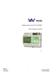
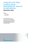
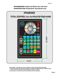
CandCNC
1.627"
FeatherTouch
Ohmic Sensor
WARNING
Use with
Floating
Torch Only
Power
SENSE
FeatherTouch™ Ohmic Sensor
for
CandCNC BladeRunner. Plazpak
and MP3000-DTHC(II) units.
For REV1 & REV2 Units
OUT
IN
FRONT SIDE VIEW
2.502"
MANUAL RELEASE 5
4
OUT
6 5 4 321
3
2
1
21
Z
HOME
NC
COM
+ DC
LIMITS
- DC
Limit
String
Z
IN Switch
Plate Tip
(WC)
If your lable shows TIP as
2 and Plate as 1, it is
WRONG. Use this manual
The CandCNC FeatherTouch Ohmic Sensor Module is designed to work with all existing CandCNC plasma
controls including all MP1000-THC, MP3000-DTHC/DTHCII, BladeRunner Dragon-Cut, and Plazpak systems. It
uses an active circuit to sense the tip of the torch touching the plate (material to be cut). It is totally isolated from the
normal inputs to the Table I/O. The inputs on all CandCNC interface and BoB products have always been isolated
from the PC ground to both prevent spikes and surges from harming sensitive port inputs on the PC and to reject
noise that might come through sharing a dirty ground. The Table I/O inputs all use the same input common and it is
designed to “float” and not be attached to a circuit that has a ground connection to the table (i.e. switches and
devices not connected to the table electrically). If you allow one side of the Table I/O circuit to be connected to the
table side ground than the isolation is partially or completely defeated. Noise from plasma cutting is exponentionally
higher than from routing or milling setups and needs to be considered in any input or sensor feed to the controls
The Ohmic Touch circuit is operated from it’s own stand-alone power source ( 9 to 14VDC wallplug) and it’s output is
opto isolated so it can maintain the integrity of the noise canceling and isolated inputs of the Table I/O. It’s sensor
input is surge and voltage protected so normal plasma start and run voltages do not effect it. It offers a fairly low
sense impedance and filtering to prevent false triggering.
Here is a list of rules to follow to get good results:
1. Always use the Ohmic Touch with a backup sensing system that will stop down motion if the sensor fails to work.
This can happen on dirty, oily, rusty or painted metal. The Floating Torch Holder (mechanical Touch-off) acts as both
a mechanical shock absorber and a limit switch to protect the torch from damage. DO NOT RUN WITHOUT A
BACKUP MOTION LIMIT.
2. Keep the tip of the nozzle on your torch clean and free from trash and slag. If you start to have contact problems
on material that is rusty or dirty, keep a spray bottle of water handy and wet down the surface for better conduction..
3. Be careful to observe polarity when hooking up the Inputs to the Torch Tip and Plate (ground) terminals. A
reversed connection can result in a false signal and possible damage if left connected wrong.
4. The DC power terminals are marked for polarity. Do NOT reverse connect a source of DC or you will damage the
module. If in doubt, meter it out! The + must go in the side marked + on the label.
5. Make sure to go though the hookup and calibration to test the proper functions of the Ohmic touch and the backup
limit to stop the motion.
6. Do not attempt to use ohmic touch with unshielded consumables. it won’t work. Some consumables may need
special shields (like the Hypertherm Fine Cut with a special Ohmic shield)
7. The ohmic touch is designed for use with automated plasma cutting using controls from CandCNC. We cannot
support other uses or interface to outer users systems..
FT-01 FeatherTouch Ohmic Sensor for use with
CandCNC BladerRunner Dragon-Cut , BladeRunner
Ether-Cut, MP3000-DTHCII, MP3100-DTHCIV
MP3500 and Plazpak.
REV 6 Manual
4/15/14
CandCNC
FeatherTouch
Ohmic Sensor
WARNING
Use with
Floating
Torch Only
Power
SENSE
OUT
IN
To Torch Tip
(Ohmic tab)
1
#2 pin blocked
4
3
2
To PLATE
(Machine Frame)
1
Z home
Common
+ DC
LIMITS
- DC
Old Touch Switch COM
Old Touch Switch NC
4
OUT
6 5 4 321
3
2
1
21
Z
HOME
NC
COM
+ DC
LIMITS
- DC
Limit
String
Z
IN Switch
Plate Tip
(WC)
This manual contains new connection suggestions for the FT-01
based on previous manuals. If you already have an FT-01 installed
and working you should review this manual and determine if you
should make changes to the installation
IMPORTANT INFORMATION:
It has been brought to our attention that with the old touch-off swtich wired to
the table I/O limits input as per the previous manuals, the swtich does NOT
stop motion if the Z is a homing move and the FT-01 fails to sense. In this
manual we have changed where the Z safety switch is connected so it now
functions as an E-stop rather than a limit. The previous labeled LIMITS wire
(Green) in the UTP cable is now no longer connected to the 5 wide connector
but is connected as shown.
UPDATE 4/15/14: The above modification is now
part of the new REV 12.2 version card and does
not need to be done to get the FT-01 and the
old Z switch to trigger an E-stop . You can
disregard the instructions to remove the green
wire from the connector. To check the REV level
of your card please see the drawing below
CandCNC label, Part
name and REV Level
located on top of card in
the area shown (white on
green prinitng)
Connecting up the old TOUCH=OFF switch (Z Safety Switch)
1. You should check your Z safety switch and make sure it can be wired as Normally
Closed. That means there is conduction between the COM and the NC terminal when
the switch is not activated and it OPENS (no conduction) when the switch is activated
(Tripped). Use an ohmmeter or continuity tester to check the switch. THE E-STOP
INPUT SIGNAL IN MACH CANNOT BE CHANGED to make it work with a Normally
open. There are other switches in the EPO circuit (in series ).
2. When you strip jacket off the UTP cable to expose the individual wires take off
enough so you can make the green LIMIT wire about 3 to 4 inches longer than the
others.
3. Strip back about 1/4” of insulation off the green wire and apply a .250 Crimp-on
terminal to the exposed wires.
4. Remove the factory supplied jumper wire across the EPO (E-Stop) tabs on the Table
I/O card.
5. Temporally plug the LIMITS wire to the EPO terminal as shown in the illustration.
Measure so the remaining wires in the UTP will reach the header fo the 5 pin connector
and cut them off.
6. Unplug the Limits wire and strip each wire in the UTP cable so about 3/16” is
exposed and insert them in the screw terminal openings in the 5 pin connector as
shown. It is important that the insulation is off back far enough that the exposed wires
are making good contact with the metal contacts in the screw terminal but that the bare
wires do not stick out far enough that they can touch each other. Poor wiring on this
plug is the leading cause of problems with the FT-01 not working.
7. Once you have the 5 wide plug wired insert it into the header on the board as shown
and reconnect the Green Limits wire over to the OUTSIDE EPO TAB (closest to the
edge with the other TABS) tab as shown.
To test the EPO part of the install power everything up and take MACH out of RESET.
IF you cannot get MACH to come out of reset and you have an “External E-STOP
Event “ error flash in the diagnostics screen than the Z safety is either not wired as
Normally Closed . or there is a wiring problem with the 5 wide connector.
Connecting up the Z Safety Switch (CONT)
8. To test if the EPO is still working, temporarily short across the two EPO pins and
make sure you can come out of RESET . In systems with an ESP or ESPII power
supply from CandCNC (BladeRunners, Plazpaks,) the Motor DC Power MUST be ON
before you can come out of RESET.
9. You MUST have the LIMIT STRING jumper in place on the FT-01 module of LIMIT
STRING or you must have a string of Normally Closed switches connected in series
into these inputs.
10. The previous “LIMIT” switches on your system will become E-STOP switches
when wired in through the FT-01. If you want to keep them as LIMITS, you will need to
wire the two ends of the string with one end tied to any of the Table I/O common TABS
(inside row), and the other end into the old LIMITS input (center terminal) on the 5 pin
connector. You will need to setup you LIMITS as before using the X++ (X limits) input.
11. It is highly recommended that you get your system moving and cutting using the Z
switch wired as a touch-off switch per the user manual of the controller model you are
using BEFORE you add the FT-01 into the mix and start changing the E-Stop
connections.
212 732
212 733
219 676
212 724
212 734
226 763
Note. Your ohmic sensor for your torch may be different
that those shown here. The objective is to have a
connection to the shield at the tip of the torch and it is not
connected to the body of the torch or touching the frame
of the torch holder.
Shield sense tab provides feedback to a
compatible torch height controller before
starting the cutting process. Place the shield
sense tab between the cup and shield.
Newer 45/65/85/105 consumables for Machine Torch
Ohmic Retaining Cap
Hypertherm Part # 220953
FineCut Consumables
Ohmic Shield
Hypertherm Part # 220948
220930
Fine Cut
Nozzle
Normal Fine Cut uses unshielded
ring. Will not work with Ohmic Touch
CandCNC
FeatherTouch
Ohmic Sensor
Power
SENSE
WARNING
Use with
Floating
Torch Only
OUT
IN
1
Z home
Common
+ DC
LIMITS
TORCH
BODY
- DC
#2 pin blocked
Torch Holder (part of table structure)
4
3
2
1
4 Wide Pluggable
Screw terminal
Touch Switch COM
Touch Switch NC
TERM2
(PLATE)
Stranded Insulated
Wire size 24 -to 16ga
TERM 1
Ohmic Tab
Insulated Barrel
(Retaining Cup)
1. Attach the Ohmic Sensor module close to
the torch mount on the Z carriage. Use a Velcro strip
2. BE CAREFUL of POLARITY when making the
connections. If the PLATE and TIP leads are
connected backwards and the torch is fired possible
damage to the Ohmic Sensor Module is possible. Units
Ohmic Connection Tab are not repairable.
(Shield Sense Tab)
Mechanized Shield
(TIP)
Requires special Ohmic Consumable
See your torch vendor for ordering
NOTE: SOME REV1 UNITS HAD THE TERMINALS
MARKED WRONG ON THE LABEL SEE THE
DIAGRAM ON PAGE 1
3. The PLATE lead must be connected to metal that
is part of the cutting grid (where the metal to be cut
is placed) Most tables are electrically connected
between the gantry and fable parts and the cutting grid.
If your table has a separate table for cutting make sure
it is attached to the gantry superstructure and torch
holder via a strap or you will have to extend the PLATE
wire (Term 2) down to the actual plate you are cutting.
4
OUT
6 5 4 321
3
2
1
21
Z
HOME
NC blocked
#2 pin
COM
+ DC
LIMITS
- DC
Z
Limit
String
Plate Tip
(WC)
IN Switch
Jumper MUST be in place on installs
that do not have a string of LIMITS
already setup. See the instructions
for more details
These Wires are
not part of the
cable bundle and
are not supplied
Shipped
Jumpered
See text to use
as part of string
of limits
NO
COM
U
TP
CA
NC
BL
E
Existing Touch-off
Switch on Floating
Torch Holder wire as
NORMALLY CLOSED
Table I/O REV 6 - 8 versions
Earlier versions will work as well
1
J2
T9
T5
6
K
C&CNC
TABLEI/O
UP
+ DC
10
UP
- DC
D17
K
DOWN
K4
D2
LIMITS
D18
K
J4
T6
T2
T7
T3
DOWN
K
T20
EPO
K4
K4
NO Com2
LIMITS
D7
T19
T18
K3
AHome
48
K
AHome
K4
C4
T16
K4Panel
COM J5
D6
T17
T14
K3
K
ZHome
K3
D5
T15
K
YHome
T10
T12
D4
T13
K
Xhome
C15
ARC
OK
T11
D15
K
OK
D3
DANGER! DANGER!
Xhome YHome ZHome
D11
NO J18
K
NOTE: The indicators
on the Table I/O card
will light when the
signal is active (ON)
between the input
terminal and the
Common terminal
across from it (inner
Table I/O Card
row). It will give you
Located inside
visual indication that
BladeRunner and the signal is getting to
newer Plazpaks
the inputs and that the
Table I/O is connected
to the UBOB card in
the controller.
TABLE I/O REV 8 w/ Ohmic Sensor Interface Card
COM
NO
K4
R4
K4Panel
K3
J17
R2
J4
K4
K3OUT
10
NO Com2
D11
C&CNC
TABLEI/O
REV8
K
J14
Remove factory
jumper.
Table I/O REV 6 - 8 versions
Earlier versions will work as well
D10
K3
R1
DANGER! DANGER!
K
R3
K4
D3
K3
To UBOB III
Card
T13
Common
LIMITS
+DC
-DC
T14
ZHome
T7
T12
End view
X
1
6
QUAD
RELAY
1
D16
UP
K
C6
K
C7
D17
D18
DOWN
K
C8
D8
LIMITS
K
AHome
D7
K
AHome
K
D6
K3
ZHome
D5
K
C9
D15
D4
K
YHome
T15
A Home (if used)
T8
ARC
OK
K
C3
T3
T10
C2
T4
AUX0
DOWN (PORT2]
Xhome YHome
UP
T9
T20
Xhome
Power
LED
T5
T11
C1
+
Com
T21
EPO
ARC
OK
K3Panel
K4
D2
This connection changed from previous
manual to use old touch=off switch in NC
mode to E-Stop the system
Strip wires and
attach plug as
Shown
To 9 - 14VDC power source
#2 pin blocked
C
-D
ZH
Co
om
mm
e
on
LI
M
IT
S
+D
C
The 35 ft UTP cable is shipped with the 6
wide IDC connector attached and the other
end of the cable unterminated. The 5 pin Mini
Eurostyle plug is shipped un-attached to
35 ft UTP the cable so the cable is easier to thread
down exiting cable routes. Cut the cable to
Cable
length then Strip the wires on the
unterminated end and carefully wire the wire
colors as shown. It is important that you get
the wires oriented as shown. the 5 pin and
jack are keyed so it only fits one way. Plug it
in the jack first to determine the orientation.
NOTE in the cable there are 8 wires but
only 5 are used. The White/Green wire and
the Brown and White/Brown are NOT used.
TO FT-01 Ohmic Sensor module
1
TABLE I/O REV 10 w/ Ohmic Sensor Interface Card
REV 10 Table I/O was released to production 2/15/13
Yhome
T13
T12
D4
Xhome
ToUBOB
Lim
its
ut C
O
Z Ho M
me
Inp
J2
1
6
1
C6
C9
C5
C8
ARC
C4
C2
C3
ZHome
T14
D5
C
10
K4
C1
OK
AHome
T16
D6
+D
QUAD RELAY
K3
D3
D10
LIMITS
T17
T18
InsideRow
COMMON
T19
T6
D8
S
DOWN
T2
YHome Xhome
T15
This connection changed from previous
manual to use old touch=off swtich in NC
mode to E-Stop the system
35 ft UTP
Cable
#2 pin blocked
PO
UP
T7
D18
T3
ZHome
-
T9
D16
D7
T5
R3
D15
EG
N
Remove factory
jumper.
T10
AHome
1
T20
FT-01
NC
DOWN LIMITS
X
5
EPO
+
UP
FT-01
PWRIN
D12
J1
J3
T11
Strip wires and
attach plug as
Shown
C
D
Most wallplug supplies have
the Positive lead with a stripe.
it is best to test the leads with
a meter for + and neg (DC
VOLTS). If the leads get
reversed it will not damage
anything but the FT-01 will not
power up.
DANGER!
K4
C&CNC
TABLEI/O
REV10
COM
J17
K3OUT
NO
J14
R1
K4
D2
T21
DANGER!
K3
++
D11
K3 R2
---
K4 J4
20A240VMAX
K3
DANGER!
+++
NO Com2
9 - 14VDC
Floating
(wallplug)
This change is not needed on the rev
12.2 and later cards see the Note at the
bottom of the page and the next page
1
Shown Above: New Table I/O REV 10 table I/O card. This card is a redesign. The PORT 2 inputs are
removed (not used). Jack for Ohmic Sensor is added along with the floating power input for the Ohmic
Sensor Module. It uses the same cable as the previous REV 8 model with the Ohmic Sensor Interface
Card. The normal Port 1 inputs and outputs are the same as the previous Table I/O cards although the
exact position on the cards has changed. The card is smaller and easier to get into tight spaces. The
35 ft UTP cable is shipped with the 6 wide IDC connector attached and the other end of the cable
unterminated. The 5 pin Mini Pluggable Termial is shipped un-attached to the cable so the cable is
easier to thread down exiting cable routes. Cut the cable to length then Strip the wires on the
unterminated end and carefully wire the wire colors as shown. It is important that you get the wires
oriented as shown. the 5 pin and jack are keyed so it only fits one way. Plug it in the jack first to
determine the orientation. NOTE: in the cable there are 8 wires but only 5 are used. The White/Green
wire and the Brown and White/Brown are NOT used. Cut them off If you have enough length you can
use them for the wires to connect your TIp and Material (plate) wires and/or your old touch-off switch.
NOTE THE REV 12.2 CARDS RELEASED
4/15/14 HAVE THE LIMITS NOW CONNECTED
TO THE EPO ON THE CARD . YOU DO NOT NEED TO
REMOVE THE GREEN WIRE FROM THE CONNECTOR.
TABLE I/O REV 12 w/ Ohmic Sensor Interface Card
BY-PASS OPTION SWITCH FOR E-STOP
( not included in FT-01 kit)
You can setup a bypass
ToUBOB
10
J2
K4
C1
ZHome
T14
D5
Yhome
Lim
its
me
1
6
See notes for
12.2 and
later cards
C6
C9
C4
ARC
C3
C5
C8
AHome
T16
D6
Z Ho
1
OK
LIMITS
T18
YHome Xhome
T15
T13
T12
D4
Xhome
Most wallplug supplies have
the Positive lead with a stripe.
it is best to test the leads with
a meter for + and neg (DC
VOLTS). If the leads get
reversed it will not damage
anything but the FT-01 will not
power up.
DOWN
T6
D8
ZHome
T17
-D
UP
T19
C
EG
N
T9
D16
T2
D7
T7
D18
T3
C2
T10
T5
R3
D15
1
AHome
FT-01
T20
InsideRow
COMMON
QUAD RELAY
K3
D3
D10
+
DOWN LIMITS
X
5
EPO
T11
UP
FT-01
PWRIN
D12
J1
J3
Strip wires and
attach plug as
Shown
DANGER!
K4
C&CNC
TABLEI/O
REV10
COM
J17
K3OUT
NO
J14
R1
K4
D2
T21
DANGER!
K3
++
D11
K3 R2
---
K4 J4
20A240VMAX
K3
DANGER!
+++
NO Com2
9 - 14VDC
Floating
(wallplug)
switch and locate it close to
the operator so you can
bring MACH out of RESET
and manually jog the axis off
the switch to clear the
condition. The switch needs
to be a MOMENTARY type
so it won’t be left on and
defeat the E-STOP from the
Z Safety and any LIMITS
connected through the FT01.
Normally Open
Momentary
Switch
Press to Bypass
E-STOP
FROM Z Safety
You will need to crimp two wires into the EPO Tab that has the green wire. Cut off the crimp
terminal on the Green wire and strip back the insulation on both wires and carefully warp the
wire from one side of the Bypass Switch around the green wire and then crimp the pair into the
fresh crimp-on terminal. The type of switch used for the Bypass is not critical as long as it is
Normally Open and closed when you push it. When you release it should return to Normally
Open. Most pushbutton switches are configured this way. Because the circuti is NC most of
the time noise on the Bypass Switch or wires has no effect .
NOTE: This can be used on any Table I/O version shown if the EPO is used for other E-STOP
inputs.
See the next page to wire the 5 wide green connector
on the rev 12.2 and later versions of the card.
The green wire is left the connector
TABLE I/O REV 12.2 w/ Ohmic Sensor Interface Card
BY-PASS OPTION SWITCH FOR E-STOP
( not included in FT-01 kit)
You can setup a bypass
DANGER!
ToUBOB
C1
J2
1
6
C6
C9
C5
C8
C4
C3
1
OK
AHome
T16
D6
ZHome
C2
ARC
T18
YHome Xhome
T15
T14
D5
Yhome
me
LIMITS
ZHome
T17
Z Ho
DOWN
T6
D8
T19
T13
T12
D4
Xhome
InsideRow
COMMON
UP
T2
Lim
its
T9
D16
T7
D18
T3
D7
T5
R3
D15
T10
AHome
Most wallplug supplies have
the Positive lead with a stripe.
it is best to test the leads with
a meter for + and neg (DC
VOLTS). If the leads get
reversed it will not damage
anything but the FT-01 will not
power up.
1
T20
-D
FT-01
DOWN LIMITS
X
5
EPO
+
UP
FT-01
PWRIN
D12
J1
T11
C
EG
N
10
K4
D10
K3
K4
D2
T21
J3
Strip wires and
attach plug as
Shown
QUAD RELAY
K3
D3
R1
K4
C&CNC
TABLEI/O
REV10
COM
J17
K3OUT
NO
J14
K3
++
D11
K3 R2
---
K4 J4
20A240VMAX
DANGER!
DANGER!
+++
NO Com2
9 - 14VDC
Floating
(wallplug)
switch and locate it close to
the operator so you can
bring MACH out of RESET
and manually jog the axis off
the switch to clear the
condition. The switch needs
to be a MOMENTARY type
so it won’t be left on and
defeat the E-STOP from the
Z Safety and any LIMITS
connected through the FT01.
Normally Open
Momentary
Switch
Press to Bypass
E-STOP
FROM Z Safety
Using .250 quick connect crimp on terminals crimp the wires from both sides of the Bypass
Switch around the green wire and then crimp the pair into the fresh crimp-on terminal. The
type of switch used for the Bypass is not critical as long as it is Normally Open and closed
when you push it. When you release it should return to Normally Open. Most pushbutton
switches are configured this way. Because the circuit is NC most of the time, noise on the
Bypass Switch or wires has no effect .
NOTE: This can be used on any Table I/O version shown if the EPO is used for other E-STOP
inputs.
NOTE THE REV 12.2 CARDS RELEASED
4/15/14 HAVE THE LIMITS NOW CONNECTED
TO THE EPO ON THE CARD . YOU DO NOT NEED TO
REMOVE THE GREEN WIRE FROM THE CONNECTOR.
Put the green wire into position 3 (center)
SETUP AND TESTING:
1. Make the connections between the Ohmic Sensor and the Table I/O card as shown on page # . . Provide DC
power to the module. Modules ship with a DC wallplug power supply that should be used unless you have access
to a source of FLOATING (ground neg side is not tired to any other circuit). See the section power hookups and
options.
2. Make sure the wire jumper is in place at the location indicated. The jumper is applied at the factory and only
should be removed if you are going to integrate the LIMIT for the touch off in with existing limits on your table (see
section on hooking to existing limit string.
3. Use the section on hooking up the touch-off switch (not part of the Ohmic Touch kit) on your Floating Torch
Holder.
4. Plug in the power to the Ohmic Sensor. Confirm that the power LED (Green) is on. If it is not unplug it
immediately and locate the cause of the lack of power to the module using a DVM
5. Check the settings on your Limits input. The limit input is port 8 pin 11 in all most UBOB based systems. (new
Ether-Cut system is an exception) At least one of the ++ or – signal (usually X--) needs to be Enable (green check)
if you are using it for just the touch off. It has to be set different than if you are using other limits in a normally
closed string
THIS SECTION HAS BEEN SUPERCEDED BY USING THE Z SAFETY SWITCH AS AN E-STOP
THIS IS INCLUDED ONLY IF YOU WANT TO CONTINUE TO USE AN EXISTING STRING OF LIMITS
WIRED DIRECTLY TO THE TABLE I/O
This needs to be
turned on
(enabled) for
LIMIT INPUT to
work. Active Low
setting detemines
if it trips on NO or
NC switch action.
Use this setup if you have no limits setup and are connecting the LIMITS up
directly to the table i/o and NOT through the FT-01. IF they are connected
through the LIMITS STRING input terminals on the FT-01 they are Np longer
Limits and become part of the E-STOP chain
What to do if you already have a string of LIMITS
OPTION ONE (add the Z Safety touch switch into the existing limits string of NC switches)
1. Using the screw access on top, Remove the jumper from the LIMIT STRING INPUT
2 Remove the ends of the limit string from the limit terminals on the Table I/O card and re-route them to the.LIMIT.String
Input.
3 Wire your Touch off switch on the Floating Holder as Normally Closed (NC) by using the COM and NC terminals on
the switch.
4. The Touch Off switch is now in the limit string and ANY switch that is activated including the Touch off should cause
MACH to go into reset. You no longer need to define any LIMITS (++ or - - inputs) since the old limit string is
now part of the E-STOP (EPO) string
OPTION TWO (Use the limit string wire directly to the LIMIT input on the Table I/O ) You can setup your LIMITS as
shown in the Ports & PIns.
Ports & Pins setup screen from Ether-Cut systems that have a PORT2 set of inputs to allow the LIMITS
input tab on the table I/O board to be used. This is ONLY if you want separate LIMITS and E_STOP
FOR SETUPS THAT HAVE EXISTING SEPARATE LIMITS ON
OTHER AXIS USING a NC STRING OF SWITCHES:
(if you do not have this setup then (disregard this page)
Note Your switch pinout
may be different
SEPARATE LIMIT SWITCHS (Normally Closed)
NO
COM
NC
THIS SETUP PUTS THE LIMITS in the STRING INTO
the E-STOP circuit and they operate as part of the
ESTOP and no longer just limits. They will NOT
be ignored durign a Homing Move
End of Limit
String
Beginning of Limit
String
4
OUT
6 5 4 321
3
2
1
21
Z
HOME
LIMITS
NC
COM
+ DC
- DC
Limit
String
Z
IN Switch
Tip Plate
(WC)
1. Take Limit string loose from Table I/O card
2. Remove jumper on limit string
3. Put two ends of limit string into the LIMIT STRING terminals
4. Connect the LIMITS OUT wire (white in this manual) as
shown to LIMITS input terminal.
5. Make sure your Z switch is wired Normally Closed (NC)
6. See previous pages for connection to Table I/O card