1
z
ne
bey
bex
bmz
ne
bex
bey
ne
bez
bmx
bmy
bez
nm
bez
bmy
bmx
ne
ne
bez
bey
bex
x
ne
ne
bmz
bey
y
bex
ne
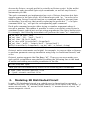
In this model, electric circuit and magnetic circuit are interlaced, the cell size
(branch length) is 2 grids, so each cell contains 8 grids which are listed below.
Grid type
Symbol
Position in the cell
Electric circuit node
ne
[0 0 0]
Electric circuit branch (along x-direction)
bex
[1 0 0]
Electric circuit branch (along y-direction)
bey
[0 1 0]
Electric circuit branch (along z-direction)
bez
[0 0 1]
Magnetic circuit node
nm
[1 1 1]
Magnetic circuit branch (along x-direction)
bmx
[0 1 1]
Magnetic circuit branch (along y-direction)
bmy
[1 0 1]
Magnetic circuit branch (along z-direction)
bmz
[1 1 0]
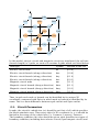
Thus, in spdc each node or branch can be identified by its unique 3D
coordinate, compared with Spice in which node or branch is identified by its
name. This is a main difference between spdc netlist and Spice netlist.
3.1.
Circuit Parameters
In spdc, the circuit's cuboid size (sc) should be set first of all, which specifies
the whole simulate zone. Then every object's 3D coordinate (x, y, z) should be
limited in the range of the cuboid size, i.e. 1≤x≤scx, 1≤y≤scy, 1≤z≤scz.
The boundary condition (bc) also should be given. spdc provides two types of
boundary condition, including short electro circuit (open magnet circuit) and