1
UM0402
User manual
Single-phase multi-tariff energy meter
Introduction
This user manual describes the functions and features of the single-phase multi-tariff energy
meter.
The reference board is an integrated system designed to provide a complete, ready-to-use
energy meter application. It is a medium-end solution for power metering, using the
ST72F321 microcontroller, the M41T94 Real Time Clock, the M95256 EEPROM and the
STPM14 energy meter ASSP device.
The multi-tariff energy meter reference board implements several features including multitariff management, absolute and average maximum demand calculation, two types of
tamper management and power failure management. It can therefore be used as a platform
for evaluation and development of meter applications.
The aim of this guide is to provide:
April 2007
■
Procedures for getting the reference board functioning quickly
■
An overview of the implementation of meter main features
■
The information required to be able to customize meter features.
Rev 1
1/35
www.st.com
Contents
UM0402
Contents
1
2
3
4
5
Overview . . . . . . . . . . . . . . . . . . . . . . . . . . . . . . . . . . . . . . . . . . . . . . . . . . 4
1.1
Safety rules . . . . . . . . . . . . . . . . . . . . . . . . . . . . . . . . . . . . . . . . . . . . . . . . 4
1.2
Conventions . . . . . . . . . . . . . . . . . . . . . . . . . . . . . . . . . . . . . . . . . . . . . . . . 4
1.3
Multi tariff meter description . . . . . . . . . . . . . . . . . . . . . . . . . . . . . . . . . . . . 4
1.4
Multi tariff meter features . . . . . . . . . . . . . . . . . . . . . . . . . . . . . . . . . . . . . . 6
1.5
Recommended reading . . . . . . . . . . . . . . . . . . . . . . . . . . . . . . . . . . . . . . . 6
1.6
Obtaining technical support . . . . . . . . . . . . . . . . . . . . . . . . . . . . . . . . . . . . 6
Getting started . . . . . . . . . . . . . . . . . . . . . . . . . . . . . . . . . . . . . . . . . . . . . . 7
2.1
Multi-tariff meter checklist . . . . . . . . . . . . . . . . . . . . . . . . . . . . . . . . . . . . . . 7
2.2
Equipment requirements . . . . . . . . . . . . . . . . . . . . . . . . . . . . . . . . . . . . . . 7
2.3
Installing the hardware . . . . . . . . . . . . . . . . . . . . . . . . . . . . . . . . . . . . . . . . 7
Hardware Features . . . . . . . . . . . . . . . . . . . . . . . . . . . . . . . . . . . . . . . . . . 8
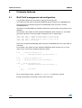
3.1
Electrical parameters . . . . . . . . . . . . . . . . . . . . . . . . . . . . . . . . . . . . . . . . . 8
3.2
Mechanical outlines . . . . . . . . . . . . . . . . . . . . . . . . . . . . . . . . . . . . . . . . . . 9
Firmware features . . . . . . . . . . . . . . . . . . . . . . . . . . . . . . . . . . . . . . . . . . 10
4.1
Multi Tariff management and configuration . . . . . . . . . . . . . . . . . . . . . . . 10
4.2
Maximum demand management and configuration . . . . . . . . . . . . . . . . . 11
4.2.1
Day type maximum demand . . . . . . . . . . . . . . . . . . . . . . . . . . . . . . . . . 11
4.2.2
Month type maximum demand . . . . . . . . . . . . . . . . . . . . . . . . . . . . . . . 12
4.2.3
Quarter type maximum demand . . . . . . . . . . . . . . . . . . . . . . . . . . . . . . 12
4.3
Date and time configuration . . . . . . . . . . . . . . . . . . . . . . . . . . . . . . . . . . . 13
4.4
Memory structure . . . . . . . . . . . . . . . . . . . . . . . . . . . . . . . . . . . . . . . . . . . 13
4.4.1
Common storage for all maximum demand types . . . . . . . . . . . . . . . . . 13
4.4.2
Storage specific for day type MD . . . . . . . . . . . . . . . . . . . . . . . . . . . . . . 16
4.4.3
Storage specific for month type MD . . . . . . . . . . . . . . . . . . . . . . . . . . . . 16
4.4.4
Storage specific for quarter type maximum demand . . . . . . . . . . . . . . . 17
Multi-tariff meter operation . . . . . . . . . . . . . . . . . . . . . . . . . . . . . . . . . . . 18
5.1
Normal operation . . . . . . . . . . . . . . . . . . . . . . . . . . . . . . . . . . . . . . . . . . . 18
5.1.1
2/35
Tamper mode . . . . . . . . . . . . . . . . . . . . . . . . . . . . . . . . . . . . . . . . . . . . . 18
UM0402
Contents
5.2
5.3
6
5.1.2
IR Mode . . . . . . . . . . . . . . . . . . . . . . . . . . . . . . . . . . . . . . . . . . . . . . . . . 18
5.1.3
LCD display . . . . . . . . . . . . . . . . . . . . . . . . . . . . . . . . . . . . . . . . . . . . . . 19
Power failure functioning . . . . . . . . . . . . . . . . . . . . . . . . . . . . . . . . . . . . . 22
5.2.1
Tamper mode . . . . . . . . . . . . . . . . . . . . . . . . . . . . . . . . . . . . . . . . . . . . . 22
5.2.2
IR Mode . . . . . . . . . . . . . . . . . . . . . . . . . . . . . . . . . . . . . . . . . . . . . . . . . 22
5.2.3
LCD Display . . . . . . . . . . . . . . . . . . . . . . . . . . . . . . . . . . . . . . . . . . . . . . 22
LCD icons description . . . . . . . . . . . . . . . . . . . . . . . . . . . . . . . . . . . . . . . 22
Additional features . . . . . . . . . . . . . . . . . . . . . . . . . . . . . . . . . . . . . . . . . 24
6.1
STPM14 programming . . . . . . . . . . . . . . . . . . . . . . . . . . . . . . . . . . . . . . . 24
6.2
In-circuit programming . . . . . . . . . . . . . . . . . . . . . . . . . . . . . . . . . . . . . . . 24
Appendix A Schematics . . . . . . . . . . . . . . . . . . . . . . . . . . . . . . . . . . . . . . . . . . . . . 25
Appendix B BOM list . . . . . . . . . . . . . . . . . . . . . . . . . . . . . . . . . . . . . . . . . . . . . . . 28
Appendix C Layout . . . . . . . . . . . . . . . . . . . . . . . . . . . . . . . . . . . . . . . . . . . . . . . . . 31
7
Revision history . . . . . . . . . . . . . . . . . . . . . . . . . . . . . . . . . . . . . . . . . . . 34
3/35
Overview
UM0402
1
Overview
1.1
Safety rules
This board can be connected to mains voltage (220V). In the case of improper use, wrong
installation or malfunction, there is a danger of serious personal injury and damage to
property. All operations such as transport, installation and commissioning as well as
maintenance should be carried out only by skilled technical personnel (regional accident
prevention rules must be observed).
Danger:
1.2
Due to the risk of death when using this prototype on mains
voltage (220V), only skilled technical personnel who are
familiar with the installation, mounting, commissioning and
operation of power electronic systems and have the
qualifications needed to perform these functions, may use
this prototype.
Conventions
The lowest analog and digital power supply voltage is called VSS. All voltage specifications
for digital input/output pins are referred to as VSS. The highest OTP writing power supply
voltage is VOTP. The highest power supply voltage of the device is VCC.
Positive currents flow into a pin. Sinking means that the current flows to the pin while
sourcing means that the current flows from the pin.
Timing specifications of signals treated by the device are relative to the CLKOUT. This signal
is fed from a 4.194 MHz on-board crystal oscillator.
Timing specifications of SPI interface signals are relative to the SCLNLC, which need not to
be in phase with CLKOUT.
A positive logic convention is used in all equations.
1.3
Multi tariff meter description
The single-phase multi-tariff energy meter reference board is designed using STPM14
metering ASSP and ST72F321BR6 microcontroller.
The STPM14 belongs to STPM1x metering devices family. It measures the active energy
that is output as a pulse train with a frequency proportional to the measured power. It
supports tamper detection, monitoring both phase and neutral line wires, where two current
transformers are used as current sensors. The clock to STPM14 is supplied by a crystal of
frequency 4.194304 MHz.
The microcontroller drives the LCD, processes measurements coming from the ASSP and
manages RTC and EEPROM functionalities, for example saving relevant data in EEPROM
before moving to halt mode during power down. It also manages maximum demand
calculation on a daily, monthly or three-month base.
4/35
UM0402
Overview
A 16 MHz crystal is used for obtaining an 8 MHz CPU clock for the micro.
This meter has SPI EEPROM (M95256) with 256 Kb of memory, and SPI RTC (M41T94) for
date and time functions. 3V rechargeable battery is used to supply RTC for when the line
power is down and the battery is fully discharged.
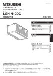
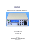
Figure 1.
Multi-tariff meter board
The board has a Viper12-based switching power supply. When line power is not available,
power to the application is supplied by 4.8V rechargeable battery.
An LCD display is present with 24x4 segments, customized for electricity meter use.
This board also supports IRDA protocol IEC62056-21 mode C.
There are two 10-pin connectors, one to program STPM14 internal OTP registers, and one
for microcontroller ICP.
Two jumpers are used for the microcontroller reset and to simulate a box tamper. A push
button is used to display various parameters on the LCD display. 30 seconds after the switch
is pressed without further activity, the LCD screen once again displays the first screen
showing accumulated kWh and eventual error symbols. However, repeated presses of the
button cycle through the display of additional information.
See Table 8 on page 19 for full details on the parameters displayed on the LCD.
5/35
Overview
1.4
1.5
UM0402
Multi tariff meter features
●
Cost-effective and flexible, based on STPM14
●
Fulfils class 1 accuracy for Ib=5A and Imax=80A according to IEC 61036:1996 + A1:
2000, Static meter for active energy (classes 1 and 2)
●
Operating Voltage range 220V ±20%
●
Continuously detects and displays No load condition, Reverse direction and fraud &
case Tamper conditions
●
Configurable number of tariffs (1 to 4) and Maximum demand Type (day type, one
month type or three month type)
●
Accumulated data for whole meter life (Total kWh consumption, Average MDs, Total
number of Tariffs, Tariff time slots, consumption under different tariff rates, power failure
date/time)
●
Data for last 12 months (Consumption under Tamper mode for each month, First/last
Case/fraud Tamper Date/time, total Tamper time and power failure accumulating time
for each month)
●
Data for Absolute Maximum Demand (Absolute MD, Date/Time) according toType of
MD requested
●
SW LCD driver for 24X4 segments LCD glass with contrast control
●
RTC with SPI exists for real Date/Time
●
EEPROM with SPI for storing 256 Kbit of data
●
Case tamper detection in power down also
●
External switch to see all the data stored into EEPROM sequentially even when AC
power is not available
●
Battery backup to detect tampering and see all the parameters stored in EEPROM
during power down also
●
Single point and fast calibration of STPM14 for Class 1 meter
Recommended reading
This documentation describes how to use the Multi Tariff Meter Reference Board.
Additional information can be found in the following documents:
1.6
●
STPM14 datasheet;
●
Components datasheets;
●
inDART-STX for ST7 User's Manuals;
●
IEC 62056 IrDA Protocol Mode C;
●
IrDA module for Multitariff Meter user manual.
Obtaining technical support
Technical assistance is provided free to all customers. For technical assistance,
documentation, information and updates about products and services, please refer to your
local ST distributor/office.
6/35
UM0402
Getting started
2
Getting started
2.1
Multi-tariff meter checklist
The Multi-tariff meter reference kit includes the following items:
2.2
●
Reference design board (Figure 1)
●
STPM14 programmer
●
An interactive CD-ROM with software and documentation.
Equipment requirements
To operate the multi-tariff meter reference board it is necessary to use a 220 V, 50 Hz AC
supplier or a simple connection to the line voltage.
2.3
Installing the hardware
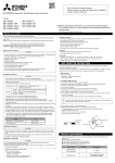
Connect the board to line and neutral wires of voltage source and to load, as displayed
below.
The line and neutral voltage source wires can be either connected to a plug, to be plugged
into the line socket, or to an AC voltage source, providing 220 VAC.
Figure 2.
Multi-tariff meter board connections
P
AC Source
N
N
P
Load
7/35
Hardware Features
UM0402
3
Hardware Features
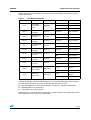
3.1
Electrical parameters
The following table summarizes the electrical parameters, which are specified for
VCC = 3.6V, TAMB = +25 C, unless otherwise noted.
Table 1.
Electrical parameters
Parameter
Min
Typ
Max
Units
Nominal line voltage VNOM
140
220
300
VRMS
Nominal frequency FL
45.0
50.0
65.0
Hz
Test Conditions or
Comments
Target applications:
Nominal line current INOM
2
Maximal line current IMAX
20
30
ARMS
+25
+85
C
0.2
0.5
Ambient temperature TAMB
-40
Class of accuracy
ARMS
Digital inputs:
15
Pull up IIL
A
Valid also for IO pins
when they are used as
inputs
Voltage input low VIL
-0.3
0.25VCC
V
Voltage input high VIH
0.75VCC
5.3
V
0.4
V
IOL = +2mA
V
IOH = -2mA
ns
CL = 50pF, VCC = 3.2V
V
Internally generated
Digital outputs:
Voltage output low VOL
Voltage output high VOH
VCC-0.4
Transition time tTR
5
OTP programming:
VDDA0.65
No programming level VVOTP
Programming level VVOTP
14
20
V
Programming current IVOTP
1
1.5
3
mA
To program 1 bit at a time
100
200
300
s
To program 1 bit at a time
3.165
3.6
5.5
V
4
5
6
mA
Supply level VDDA
2.85
3
3.15
V
Nominal frequency FL
45.0
50.0
65.0
Hz
Programming time tWE
Power supply:
Supply level VCC
Quiescent current ICC
Power on reset VCCPOR
2.5
V
SPI interface timings:
Data write speed fSCL
8/35
100
kHz
No loads
CL = 100nF, VCC = 3.2V
UM0402
Hardware Features
Table 1.
Electrical parameters (continued)
Parameter
Typ
Max
Units
Data set up time tDS
20
ns
Data hold time tDH
0
ns
Data driver on time tON
20
ns
Data driver off time tOFF
20
ns
SYN active width tSYN
3.2
Min
1000
Test Conditions or
Comments
ns
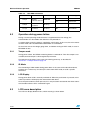
Mechanical outlines
The size of PCB of the module can be seen from an appended drawing. The overall volume
is determined by the size of maximal element, which is a current transformer:
L x W x H = 70 mm x 46 mm x 30 mm.
9/35
Firmware features
UM0402
4
Firmware features
4.1
Multi Tariff management and configuration
It is possible to define up to four tariffs to apply to the energy count.
The number of tariffs must be defined in EEPROM_Union structure in the EEPROM.c file.
Tariff-change time should also be given in the EEPROM_Union structure in 24-hour
HH:MM:SS format.
Tariff times in the EEPROM.c file should be defined in increasing order starting from the first
definition.
For example, if the number of tariffs defined in EEPROM_Union structure is 3, we should
give three tariff times in increasing order starting from first as shown below:
{
{0x05,
{0x10,
{0x21,
{0x00,
}
0x00,
0x30,
0x00,
0x00,
0x00},//
0x00},//
0x00},//
0x00},//
Change of tariff from A3 to A1 at 5:00 AM
Change of tariff from A1 to A2 at 10:30 AM
Change of tariff from A2 to A3 at 9:00 PM
Not defined
Tariff rates are defined in EEPROM_Union structure in EEPROM.c file in the same order as
tariff times.
For example, if the number of tariffs defined in EEPROM_Union structure is 3 (as in the
above case), the tariff rate should be defined as below:
{
{
3.000,
// Tariff rate defined for A1
{0, 0}
// kWh_Energy and Pulse count initialized to 0
},
{
2.001,
// Tariff rate defined for A2
{0, 0}
// kWh_Energy and Pulse count initialized to 0
},
{
2.852, // Tariff rate defined for A3
{0, 0}
// kWh_Energy and Pulse count initialized to 0
},
{
0.0,
// Not Defined
{0, 0}
},
},
To set and change the tariff, a function Set_TARIFF() is called every second.
Energy consumption is calculated as total and for each tariff.
10/35
UM0402
4.2
Firmware features
Maximum demand management and configuration
The maximum demand (MD) is the maximum continuous load (kW) which remains for a
certain period. This period is programmable and can be chosen from 1 minute up to 60
minutes. There are three types of absolute maximum demand which are defined:
a)
Daily based,
b)
Monthly based,
c)
Quarterly based.
According to this selection, the absolute maximum demand will be calculated and stored for
each day, or for each month or for each quarter in a 12 month base.
Out of these three options, one can be selected by the user in the lib.h file by preprocessor
directive; in the same way it is possible to program the period of constant load.
An example definition is given below:
/* define type for MD*/
#defineMD_minutes 1
// #defineDAY1
#defineONE_MONTH 1
// #defineTHREE_MONTHS 1
In every case the average of these maximum demands is calculated and stored for a year
as:
●
last three months average maximum demand,
●
second last three months average maximum demand,
●
third last three months average maximum demand,
●
fourth last three months average maximum demand,
●
last six months average maximum demand,
●
last nine months average maximum demand
●
last twelve months average maximum demand.
In the following paragraphs the three types of MD will be explained in detail.
4.2.1
Day type maximum demand
In this type the storing period is chosen and programmed to be one day.
As an example, the maximum load period is chosen and programmed to be 15 minutes.
If on the first day (e.g. 25th Dec'06) there is a continuous load of 150 kW for 15 minutes
starting from 10:15PM to 10:30PM, and another one of 200 kW for 10 minutes starting from
11:11PM to 11:21PM, the meter stores the value of 150 kW as the "maximum demand" of
that day with date 25th Dec'06 and time 22:30:00 in 24Hour HH:MM:SS format.
The meter acts the same way for each day. Average maximum demands are calculated
using the MD values of each day.
Then at the end of the month, the meter calculates and stores:
●
maximum demand for each day of the month,
●
average maximum demands of all types.
11/35
Firmware features
UM0402
Name
1st Jan
2nd Jan
..
..
..
27th Feb
28th Feb
29th Feb
1st March
..
..
..
..
..
..
..
..
..
..
..
..
31st Dec
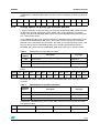
In EEPROM, the storing of the day type MD for each day is defined as below:
Index
0
1
..
..
..
57
58
59
60
..
..
..
..
..
..
..
..
..
..
..
..
365
If the particular year is a leap year, then 59th index data will be filled by 29th Feb maximum
demand, otherwise index will be incremented by 2 which leaves the 59th index maximum
demand data as it was.
4.2.2
Month type maximum demand
In this type the storing period is chosen and programmed to be one month.
As an example, the maximum load period is chosen and programmed to be 15 minutes.
The maximum demand of a day is calculated as in the previous case.
If the first day the absolute maximum demand is 150 kW, and the second day it is 75 kW, the
meter keeps the value of the 150 kW of the previous day as the maximum demand value.
If the third day the maximum demand is 200 kW, the meter stores 200 kW with new date and
time instead of the 150 kW as maximum demand of the month.
At the end of the month the meter stores only one value of maximum demand, and
calculates average maximum demands using the MD values of each month.
Then at the end of the month, the meter calculates and stores:
●
maximum demand of the month,
●
average maximum demands of all types.
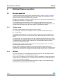
In EEPROM, the storing of month type MD for each month is defined as below:
Name
JAN
FEB
MAR
APR
MAY
JUN
JUL
AUG
SEP
OCT
NOV
DEC
Index
0
1
2
3
4
5
6
7
8
9
10
11
4.2.3
Quarter type maximum demand
In this type the storing period is chosen and programmed to be three months.
Let suppose that the maximum load period is chosen and programmed to be 15 minutes.
The maximum demand of each month is calculated as in the previous case.
Moreover, at the end of each month the maximum demand of the quarter is calculated as
the maximum demand of the three months of the quarter, and average maximum demands
are calculated using the MD values of each month.
Summarizing, at the end of month meter calculates and stores:
12/35
●
maximum demand of the month,
●
maximum demand of the quarter,
●
average maximum demands of all types.
UM0402
Firmware features
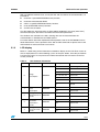
In EEPROM, in the case of three months type MD the storing of month-wise maximum
demand and three month-wise maximum demand is defined as below:
Name
JAN
FEB
MAR
APR
MAY
JUN
JUL
AUG
SEP
OCT
NOV
DEC
Index
0
1
2
3
4
5
6
7
8
9
10
11
Name
JAN, FEB, MAR
APR, MAY, JUN
JUL, AUG, SEP
OCT, NOV, DEC
Index
0
1
2
3
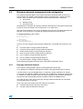
4.3
Date and time configuration
RTC date and time can be set by the firmware itself. There is a RTC_init() function which
initializes the RTC with the specified date and time. The date and time to be initialized in
RTC should be specified in RTC_table[10] array. The definition of array is as below:
RTC_table[0] = write command and 7 bit address(0x00) = 0x80
RTC_table[1] = Seconds up to 0.01 in BCD format = value given by user
RTC_table[2] = ST and Seconds in BCD format = value given by user
RTC_table[3] = Minutes in BCD format = value given by user
RTC_table[4] = CEB, CB and Hours in BCD format = value given by user
RTC_table[5] = Day of week = value given by user
RTC_table[6] = Date of month in BCD format = value given by user
RTC_table[7] = Month in BCD format = value given by user
RTC_table[8] = Year = value given by user
RTC_table[9] = calibration value = value given by user
For more information, please refer to M41T94 datasheet of RTC used in the board.
Date and time can also be set by using the IRDA protocol. Please refer to the IEC 62056
PROTOCOL MODE C user manual.
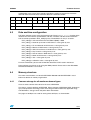
4.4
Memory structure
The meter sensitive data are stored in EEPROM. M95256 256 Kbit EEPROM is used.
Below are details on memory organization.
4.4.1
Common storage for all maximum demand types
There is some common data stored at the start of EEPROM.
This data is saved in 89 Bytes of EEPROM_Union structure of EEPROM_DATA_Union data
type, and represents the energy count, the average maximum demand, application flags,
tariff definitions, energy counts and power down information.
Two pages of 64 Bytes are used for storing these 89 Bytes, as shown below:
13/35
Firmware features
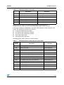
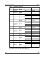
Table 2.
UM0402
EEPROM common information
EEPROM
Address
14/35
Description
Data Type
00h
kWh_Energy
unsigned long
04h
Pulse_Count
unsigned int
06h
Av_Max_Demmand_1st_three
unsigned int
08h
Av_Max_Demmand_2nd_three
unsigned int
0Ah
Av_Max_Demmand_3rd_three
unsigned int
0Ch
Av_Max_Demmand_4th_three
unsigned int
0Eh
Av_Max_Demmand_last_six
unsigned int
10h
Av_Max_Demmand_last_nine
unsigned int
12h
Av_Max_Demmand_last_twelve
unsigned int
14h
IRQTAMPER
Bool
14h
TMPD
Bool
14h
E_TAMPER
Bool
14h
First_Fraud
Bool
14h
First_Box
Bool
14h
Installation_Check
Bool
15h
Total_No_Tarrifs
unsigned char
16h
Tarrif_Time[0] : Hour,Min,Sec
unsigned char
19h
Tarrif_Time[1] : Hour,Min,Sec
unsigned char
1Ch
Tarrif_Time[2] : Hour,Min,Sec
unsigned char
1Fh
Tarrif_Time[3] : Hour,Min,Sec
unsigned char
22h
Tarrif[0] : Tarrif_Rate
float
26h
Tarrif[0] : kWh_Energy_Tarrif
volatile unsigned long
2Ah
Tarrif[0] : Pulse_Count_Tarrif
volatile unsigned int
2Ch
Tarrif[1] : Tarrif_Rate
float
30h
Tarrif[1] : kWh_Energy_Tarrif
volatile unsigned long
34h
Tarrif[1] : Pulse_Count_Tarrif
volatile unsigned int
36h
Tarrif[2] : Tarrif_Rate
float
3Ah
Tarrif[2] : kWh_Energy_Tarrif
volatile unsigned long
3Eh
Tarrif[2] : Pulse_Count_Tarrif
volatile unsigned int
40h
Tarrif[3] : Tarrif_Rate
float
44h
Tarrif[3] : kWh_Energy_Tarrif
volatile unsigned long
48h
Tarrif[3] : Pulse_Count_Tarrif
volatile unsigned int
4Ah
Index_Month_Data
volatile unsigned char
4Bh
Index_day_three_mon_Data
volatile unsigned int
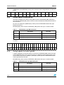
UM0402
Firmware features
Table 2.
EEPROM
Address
EEPROM common information
Description
Data Type
4Dh
power_down_date: Day, Month, Year
volatile unsigned char
50h
power_down_time: Sec, Min, Hour
volatile unsigned char
53h
pwr_dn_index_year
volatile unsigned char
54h
pwr_dn_index_mon
volatile unsigned char
55h
Index_Box_Tamper
volatile unsigned int
57h
Index_Fraud_Tamper
volatile unsigned int
Twelve pages of 64 Bytes are used for storing 456 Bytes (12x38 Bytes) of
EEPROM_month_Union structure of EEPROM_DATA_Month_Union data type.
Each page of 64 Bytes of EEPROM is separately storing 38 Bytes of data related to each
month. The information stored for each month is:
●
Energy consumption during tamper;
●
First and last box tamper time and date;
●
First and last line tamper time and date;
●
Total month tamper time;
●
Total month power down time.
EEPROM_month_Union structure is stored as below:
Table 3.
EEPROM common information (for each month)
EEPROM
Address
Description
Data Type
80h
kWh_Energy_Tamp
volatile unsigned long
84h
Pulse_Count_Tamp
volatile unsigned int
86h
First_Tamper_Time_Box : Sec, Min, Hour
volatile unsigned char
89h
First_Tamper_Date_Box : Day, Month, Year
volatile unsigned char
8Ch
Last_Tamper_Time_Box : Sec, Min, Hour
volatile unsigned char
8Fh
Last_Tamper_Date_Box : Day, Month, Year
volatile unsigned char
92h
First_Tamper_Time_Fraud : Sec, Min, Hour
volatile unsigned char
95h
First_Tamper_Date_Fraud : Day, Month, Year
volatile unsigned char
98h
Last_Tamper_Time_Fraud : Sec, Min, Hour
volatile unsigned char
9Bh
Last_Tamper_Date_Fraud : Day, Month, Year
volatile unsigned char
9Eh
Total_Tamper_Time : Sec, Min
volatile unsigned char
A0h
Total_Tamper_Time : Hour_Tamper_Time: Hour
volatile unsigned int
A2h
Power_Failure_Time: Sec, Min
volatile unsigned char
A5h
Power_Failure_Time: Hour_Tamper_Time: Hour
volatile unsigned int
15/35
Firmware features
UM0402
In EEPROM, twelve EEPROM_month_Union structures each having 38 Bytes are stored as
below:
Name
JAN
FEB
MAR
APR
MAY
JUN
JUL
AUG
SEP
OCT
NOV
DEC
Index
0
1
2
3
4
5
6
7
8
9
10
11
4.4.2
Storage specific for day type MD
46 pages of 64 Bytes are used for storing 366 structures of EEPROM_AMD_Union data
type. Current EEPROM_MD_Union structure contains the Maximum Demand information of
the current day.
So, there are 2928 Bytes (366x8 Bytes) of data present in EEPROM related to day type
Maximum Demand.
EEPROM_MD_Union structure of EEPROM_AMD_Union data type is stored as below:
Table 4.
EEPROM day type MD information
EEPROM
Address
Description
Data Type
380h
Absolute_MD
unsigned int
382h
Time_Ab_MD : Sec, Min, Hour
volatile unsigned char
385h
Date_Ab_MD : Day, Month, Year
volatile unsigned char
Name
1st Jan
2nd Jan
..
..
..
27th Feb
28th Feb
29th Feb
1st March
..
..
..
..
..
..
..
..
..
..
..
..
31st Dec
In EEPROM, 366 EEPROM_MD_Union structures each having 8 Bytes of data are stored
as below:
Index
0
1
..
..
..
57
58
59
60
..
..
..
..
..
..
..
..
..
..
..
..
365
4.4.3
Storage specific for month type MD
2 pages of 64 Bytes are used for storing 12 structures of EEPROM_AMD_Union data type.
Current EEPROM_MD_Union structure contains the Maximum Demand information of the
current month. So, there are 96 Bytes (12x8 Bytes) of data present in EEPROM related to
month type Maximum Demand.
EEPROM_MD_Union structure of EEPROM_AMD_Union data type is stored as below:
Table 5.
EEPROM month type MD information
EEPROM
Address
16/35
Description
Data Type
380h
Absolute_MD
unsigned int
382h
Time_Ab_MD : Sec, Min, Hour
volatile unsigned char
385h
Date_Ab_MD : Day, Month, Year
volatile unsigned char
UM0402
Firmware features
In EEPROM, 12 EEPROM_MD_Union structures each having 8 Bytes of data are stored as
below:
Name
JAN
FEB
MAR
APR
MAY
JUN
JUL
AUG
SEP
OCT
NOV
DEC
Index
0
1
2
3
4
5
6
7
8
9
10
11
4.4.4
Storage specific for quarter type maximum demand
2 pages of 64 Bytes are used for storing 12 structures of EEPROM_AMD_Union data type
for Maximum demand information of each month and 1 page of 64 Bytes are used for
storing 4 structures of EEPROM_AMD_Union data type for Maximum demand information
of 4 - three months blocks.
Current EEPROM_MD_Union structure contains the Maximum Demand information of the
current month and EEPROM_MD_Union_Three_Mon structure contains the maximum
demand of the current block of three months. So, there are 128 (96+32) Bytes (12x8 + 4x8
Bytes) of data present in EEPROM related to three months type Maximum Demand.
EEPROM_MD_Union structure of EEPROM_AMD_Union data type is stored as below:
Table 6.
EEPROM quarter type MD information
EEPROM
Address
Description
Data Type
380h
Absolute_MD
unsigned int
382h
Time_Ab_MD : Sec, Min, Hour
volatile unsigned char
385h
Date_Ab_MD : Day, Month, Year
volatile unsigned char
In EEPROM, 12 EEPROM_MD_Union structures each having 8 Bytes of data are stored as
below:
Name
JAN
FEB
MAR
APR
MAY
JUN
JUL
AUG
SEP
OCT
NOV
DEC
Index
0
1
2
3
4
5
6
7
8
9
10
11
EEPROM_MD_Union_Three_Mon structure of EEPROM_AMD_Union data type is stored
as below:
Table 7.
EEPROM quarter type MD information
EEPROM
Address
Description
Data Type
400h
Absolute_MD
unsigned int
402h
Time_Ab_MD : Sec, Min, Hour
volatile unsigned char
405h
Date_Ab_MD : Day, Month, Year
volatile unsigned char
In EEPROM, 4 EEPROM_MD_Union_Three_Mon structures each having 8 Bytes of data
are stored as below:
Name
JAN, FEB, MAR
APR, MAY, JUN
JUL, AUG, SEP
OCT, NOV, DEC
Index
0
1
2
3
17/35
Multi-tariff meter operation
5
Multi-tariff meter operation
5.1
Normal operation
UM0402
Connect the meter to the voltage source and to the load, as shown in Figure 2 on page 7,
and power on the board by plugging it into the AC line socket, or by powering on the AC
source to which line and neutral wires are connected.
During normal operation, the meter is supplied with the line voltage, the microcontroller is in
Run Mode and all devices are powered on.
The red LED just below the LCD blinks with a frequency proportional to active power
measured by STPM14 (pulse constant is set to 1000imp/kWh) and the LCD displays active
energy measured, current tariff and other symbols, as listed below in details.
5.1.1
Tamper mode
The meter is able to detect and manage two types of tamper:
●
box tamper (when the box is opened). This event can be simulated with jumper J1.
●
fraud tamper
The STPM14 metering device is also able to detect tamper on the line or voltage wire. If a
difference between currents in line and neutral wire is detected the device enters tamper
mode.
In normal mode, the current averages with a 50% multiplex ratio between the two channels.
In tamper mode only the higher current is used for energy computation and the other current
is monitored only to check if tamper is still present. For more details about line tamper
please refer to STPM14 datasheet.
Both box and line tamper events are detected by the microcontroller, which also records
their timestamp and other sensitive data.
During a tamper event the LCD displays the E bottom (tamper) symbol. The energy
computation is still performed and increases the total energy; moreover the meter computes
and stores the total amount of energy consummated during tamper events for each month.
5.1.2
IR Mode
The meter implements a simple IrDA communication, compliant with IEC 62056 protocol
mode C, using two led (…) as transmitter and receiver.
In this way it is possible to read all information stored in EEPROM, as energy consumption,
tamper information and MD data or to change application parameters without opening the
meter case or stopping its operation.
A firmware library has been developed to communicate, through a hand held unit (HHU)
connected to PC serial port, with a GUI interface.
18/35
UM0402
Multi-tariff meter operation
With a predefined command set, sent by the GUI and the HHU to the microcontroller, it is
possible to:
●
read from a specified EEPROM memory location,
●
read from microcontroller RAM,
●
write in a specified EEPROM memory location,
●
reset all EEPROM memory locations
●
set RTC time and date.
The GUI allows the baud rate to be set (from 300 to 19200 bps), the parity (odd / even),
communication port, data format and other communication parameters.
Two windows are available in the GUI, showing data sent and received from the
microcontroller, in hexadecimal and ASCII format.
For further details about the implemented IrDA protocol, refer to the IEC 62056 Protocol
Mode C document. For the operation of the GUI and the command set please refer to the
IrDA module for multi-tariff meter user manual.
5.1.3
LCD display
Below is a table listing all the information available for display on the LCD. Each screen of
data is displayed one at a time following a press of the push button. Once the push button
has been pressed, if it is not pressed in another 30 seconds the LCD returns to the first
screen (screen 0).
Table 8.
Screen n.
0
1
2
3
4
LCD Common Information
Data
Format
Symbol
Meaning
A
Active energy
kWh
Measure Unit
~
1
Phase 1
A1 / A2 / A3 / A4
Current tariff
E bottom
Tamper detected
Ç
Negative Power Direction
X
No Load Condition
detected
P
Power
kW
Measure Unit
Average maximum
demand for last 3 00000.000
months
P
Power
kW
Measure Unit
Average maximum
demand for
00000.000
second last 3
months
P
Power
kW
Measure Unit
Average maximum
demand for third 3 00000.000
months
P
Power
kW
Measure Unit
Energy
Consumption
Instantaneous
power
consumption
0000000.0
00000.000
19/35
Multi-tariff meter operation
Table 8.
Screen n.
5
6
7
8
9
10
11
12
13
14
15
16
UM0402
LCD Common Information
Data
Format
Symbol
Meaning
Average maximum
demand for fourth 00000.000
last 3 months
P
Power
kW
Measure Unit
Average maximum
demand for last 6 00000.000
months
P
Power
kW
Measure Unit
Average maximum
demand for last 9 00000.000
months
P
Power
kW
Measure Unit
Average maximum
demand for last 12 00000.000
months
P
Power
kW
Measure Unit
A1
Tariff symbol
A1
Tariff symbol
1
Tariff
kWh
Measure Unit
~
1
Phase 1
A2
Tariff symbol
A2
Tariff symbol
2
Tariff
kWh
Measure Unit
~
1
Phase 1
A3
Tariff symbol
A3
Tariff symbol
3
Tariff
kWh
Measure Unit
~
1
Phase 1
A4
Tariff symbol
A4
Tariff symbol
4
Tariff
kWh
Measure Unit
~
1
Phase 1
Rate @1st tariff
slot
Consumption for
1st tariff slot
Rate @2nd tariff
slot
Consumption for
2nd tariff slot
Rate @3rd tariff
slot
Consumption for
3rd tariff slot
Rate @4th tariff
slot
Consumption for
4th tariff slot
00000.000
0000000.0
00000.000
0000000.0
00000.000
0000000.0
00000.000
0000000.0
The next block of information is repeated 12 times, the first block displayed is current month
data, the others are past months going backwards for 1 year.
20/35
UM0402
Multi-tariff meter operation
Index i=0 refers to current month, it increases by one each button press up to 11 for past
months information.
Table 9.
LCD Month Information
Screen n.
Data
Format
Consumption
under tamper
mode
0000000.0
18+i*11
First box tamper
event date
dd.mm.yy
19+i*11
First box tamper
event time
hh.mm.ss
20+i*11
Last box tamper
event date
dd.mm.yy
21+i*11
Last box tamper
event time
hh.mm.ss
22+i*11
First fraud tamper
event date
dd.mm.yy
23+i*11
First fraud tamper
event time
hh.mm.ss
24+i*11
Last fraud tamper
event date
dd.mm.yy
25+i*11
Last fraud tamper
event time
hh.mm.ss
17+i*11
26+i*11
27+i*11
Total Tamper Time
hhhh.mm.ss
(Box + Fraud)
Total Power
Failure Time
Symbol
Meaning
A
Active energy
kWh
Measure Unit
~
1
Phase 1
E bottom
Tamper indicator
E bottom
Tamper indicator
Min
Time indicator
E bottom
Tamper indicator
E bottom
Tamper indicator
Min
Time indicator
E bottom
Tamper indicator
E bottom
Tamper indicator
Min
Time indicator
E bottom
Tamper indicator
E bottom
Tamper indicator
Min
Time indicator
E top
Power failure
indicator
Min
Time indicator
E top
Power failure
indicator
Min
Time indicator
hhhh.mm.ss
The next block of information is repeated 4 +12 or 12 or 365 times if the MD mode is
quarterly or monthly or daily based respectively. The first block displayed is current quarter
or month or day, the others are previous data going backwards for 1 year.
●
Quarterly AMD case: j from 0 to 15 (displays 12 months + 4 quarters information).
●
Monthly AMD case: j from 0 to 11.
●
Daily AMD case: j from 0 to 365.
Index i=0 refers to current quarter, month or day, it increases by one each button press up to
the maximum for each case for past information.
21/35
Multi-tariff meter operation
Table 10.
LCD AMD Information
Screen n.
149+j*3
5.2
UM0402
Data
Format
Absolute
00000.000
maximum demand
150+j*3
Date of
occurrence
dd.mm.yy
151+j*3
Time of
occurrence
hh.mm.ss
Icon
Meaning
P
Power
kW
Measure Unit
Min
Time indicator
Operation during power failure
During a normal operating mode the meter is supplied with the line voltage, the
microcontroller is in Run Mode and all devices are powered on.
If a power down occurs the meter is supplied by 4.8 V battery. In this case, the micro moves
to HALT mode and LCD, EEPROM and STPM14 are switched off.
As the micro senses the voltage going down, and before moving to HALT mode, it saves in
EEPROM all data.
5.2.1
Tamper mode
During power failure, the STPM14 metering device is switched off. Then line tamper is not
available, but box tamper is still recognized by the meter.
The behavior of the meter is the same of that during power up, as described in
Section 5.1.1: Tamper mode on page 18.
5.2.2
IR Mode
The functioning of IrDA module during power down is the same of that described above,
except that it is necessary, to wake up the micro from HALT mode, to send a specific
command.
5.2.3
LCD Display
During power down LCD is normally switched off. When the push button is pressed, micro
wakes up and the LCD displays the information listed above.
Once the push button has been pressed, if it is not pressed in 30 seconds the micro returns
to halt mode and the LCD is switched off again.
5.3
LCD icons description
The LCD can display different icons, which meaning is shown below.
22/35
UM0402
Multi-tariff meter operation
Table 11.
LCD Icons
Icon
Meaning
A
Active Energy
P
Active Power
kWh
Energy Measure Unit
kW
Power Measure Unit
~
1
Phase 1
A1
A1 tariff
A2
A2 tariff
A3
A3 tariff
A4
A4 tariff
E bottom
Tamper indicator
E top
Power failure indicator
Ç
Negative Power Direction indicator
X
No Load Condition indicator
Min
Time indicator
23/35
Additional features
UM0402
6
Additional features
6.1
STPM14 programming
All the configuration bits that control the operation of the STPM14 device can be written in a
temporary or permanent way (respectively in the so-called shadow registers or in the OTP
memory) through a serial interface.
Software PC GUI is available with the reference board to write calibration and configuration
bits in the device. A parallel hardware programmer interfaces the PC and the reference
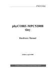
board through J2 10 pins connector, as shown in Figure 3.
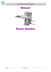
Figure 3.
Board connected to parallel hardware interface
For more details on calibration and configuration bits please refer to STPM14 datasheet.
For more details on GUI interface please refer to user manual UM0128.
6.2
In-circuit programming
The ICP feature allows you to update the contents of Flash program memory when the chip
is already plugged into the application board. ICP programming uses the ICC (In-Circuit
Communication) serial protocol to interface a programming tool like inDART®. ICP offers the
following benefits:
●
In-circuit debugging
●
Real time code execution without probes
●
Customization of the application
●
Easy application debug.
J1 10 pins connector is available for ICP functionality.
24/35
UM0402
Schematics
Appendix A
Schematics
Figure 4.
Microcontroller section schematic
+5.0VB
PA5
PA4
49
PA4
51
50
PA5
PA6/SDAI
RESET
VPP
PA7/SCLI
Vpp/ICCSEL
52
53
55
54
RESET
TLI
EVD
57
Vss_2
56 IRQSTPM
OSC2
IRIN
OSC1
59
58
OSC2
OSC1
60
Vdd_2
PE0/TDO
61
63
62
PE1/RDI
PE2
+5.0VB
46
TMPD
45
SW1
44
IRQBUTT
43
IRQRTC
C14
10NF
42
R5
41
ICCCLK
40
SDI
39
ICCDATA
38
COM1
37
COM2
36
COM3
35
COM4
0
SCL
SDO
R7
0
34
33
C19
100nF
+5.0VB
32
EXTCLK_A/PF7
47
PF7
31
PF6
ICAP1_A/PF6
30
PF5
Vdd_0
10NF
48
10k
PFD
C25
100nF
+5.0VB
ICAP2_A/AIN11/PF5
OCMP1_A/AIN10/PF4
OCMP2_A/AIN9/PF3
R1
C24
100nF
Vss_0
29
AIN3/PD3
PF4
AIN2/PD2
28
16
ei1
PF2
PD3
PC0/OCMP2_B/AIN12
27
15
PC1/OCMP1_B/AIN13
AIN1/PD1
BEEP/PF1
PD2
AIN0/PD0
MCO/AIN8/PF0
14
26
PD1
PC2/ICAP2_B
NPD
13
Vss_3
PD0
ST72F321BR6
PC3/ICAP1_B
PB7
25
12
PC4/MISO/ICCDATA
ei3
ARTIC2/PB6
24
PB7
ARTIC1/PB5
NLCD
11
PC5/MOSI/AIN14
Vdd_3
PB6
PC6/SCK/ICCCLK
SPI
ARTCLK/PB4
Vssa
10
PWM0/PB3
23
PB5
SS/PC7
22
9
PWM1/PB2
Varef
PB4
ei2
AIN7/PD7
8
PA1
PA0
21
PB3
ei0
20
7
PA2
PWM2/PB1
PD7
PB2
PA3
2
C13
100nF
Vss_1
I2C
PWM3/PB0
AIN6/PD6
6
19
5
PB1
JP1
1
Vdd_1
PE7
PD6
PB0
R38
10k
+5.0VB
C12
SCI
AIN5/PD5
4
PE6
AIN4/PD4
PE7
+5.0VB
PE5
18
3
17
PE6
PE4
PD5
2
PD4
1
EMEM
PE3
64
U6
NERTC
IROUT
C5
100nF
R2
10k
25/35
Schematics
UM0402
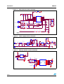
Figure 5.
Measurement section schematic
R6
D9
1
2
750
C15
1NF
C16
C17
1U
1U
C18
1U
U3
IRQSTPM
20
1
2
4
5
6
8
7
9
10
+5.0V
VOTP
R8
J4
2.2 1%
R9
2
1
1K
led
MON
MOP
Vddd
Vss
Vcc
Vdda
Votp
Ilp1
Iln1
C20
no mounted
R10
Sda
Scl
Scs
Syn
CLKout
CLKin
Vin
Vip
Iln2
Ilp2
TMPD
NLCD
SCS
NPD
19
18
3
15
17
16
14
13
12
11
Y1
STPM14
4.194304MHZ
10NF
R11
R13 1K
R14 2M
CURRENT TRANSFORMER
2,21K
1M R12
R15 1K
C21
J5
2.2 1%
R16
2
1
C22
15PF
C23
no mounted
R17
15PF
R19
R18
10NF
150K
2M
R20 1K
CURRENT TRANSFORMER
C26
33nF
R21
R22
R23
270K
270K
200K
PHASE
PHASE
R24
470
MAINS
230 Vac
Power supply section schematic
D12
DZ1
9.1VZ
D2 600V
1A
D3
LL4148
RF1
PHASE
1
10R 1W
CON1
1000V 1000V
1A
1A
C6
1UF
450V
C7
1UF
450V
8
7
6
5
D
D
D
D
C3
50V
C2
22NF 25V
10UF
S
S
FB
VDD
1
2
3
4
+ C1
100µF
PFD
C4
25V
100NF
R3
22E
0.25W
D8
STTH1L06
600V
1A
C8
47UF
25V
DZ2
10VZ
+5.0VB
U2
L78L05AC
8
7
6
5
1MH L1
250mA
VIPER12ADIP
RV1
275V 8.6J
J2
U1
D6
D5
1N4148
STTH1L06
VIN VOUT
GND GND
GND GND
NC
NC
C9
100NF
25V
D13
1
2
3
4
D4 BAT49
R4 5K
1N4148
BT1
+ C10
100uF 25V
+ C11
100µF
4.8V
1
L1 BC1
470UH 100MA
J1
+5.0V
D11
1N4148
L2
1uH 150mA
1
CON1
Mains 230 VAC
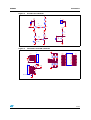
Figure 7.
Memory and RTC section schematic
+5.0VB
+5.0VB
U4
SCL
SDI
C27
100NF
8
7
6
5
Vcc
S
HOLD Q
C
W
D
Vss
M95256
1
2
3
4
EMEM
SDO
C28
Y2
32.768KHZ
R37
15PF
C29
1M
BT2
2
15PF
BATTERY 3V
XI
Vcc
XO
NE
NRST NIRQ/FT/OUT
WDI
THS
NRSTIN1
SDI
NRSTIN2
SQW
VBAT
SCL
Vss
SDO
M41T94
1
26/35
+5.0VB
U5
1
2
3
4
5
6
7
8
2
Figure 6.
16
15
14
13
12
11
10
9
NERTC
IRQRTC
SDI
SCL
SDO
C30
100nF
UM0402
Schematics
Figure 8.
IR and reset schematic
+5.0V
R39
39
X1
1
2
3
1
+5.0V
C33
D10
OSC1
OSC2
100nF
16 MHZ
R30
1
3k
2
2
Q3
BC847
7
IROUT
32
14
U7A
1
+5.0VB
74HC04
+5.0V
+5.0V
R35
4.7K
RESET
R41
10k
R29
10K
3
R40
220
IRIN
C31
10NF SW2
Q2
BC847
1
1
2
2
Q1
PHOTO NPN
Figure 9.
Connectors and LCD schematic
+5.0VB
J7
J6
VOTP
R25 56K
R32 56K
R33 56K
R34 56K
ICP CONNETCTOR
R28 56K
10
9
8
7
6
5
4
3
2
1
R31 56K
JA1
R27 56K
TMPD
SCS
NLCD
LED
+5.0V NPD
R26 56K
1
2
3
4
5
6
7
8
9
10
COM4
COM3
COM2
COM1
R36
10K
OSC1
+5.0VB
COM4
COM3
COM2
COM1
PF4
PD6
PD4
PD2
PD0
PB6
PB4
PB2
PB0
PE6
30
29
28
27
26
25
24
23
22
21
20
19
18
17
16
1
2
3
4
5
6
7
8
9
10
11
12
13
14
15
PA4
PA5
PF7
PF6
PF5
PD7
PD5
PD3
PD1
PB7
PB5
PB3
PB1
PE7
LCD DE7936/V
VPP
RESET
ICCCLK
ICCDATA
C32
100NF
27/35
BOM list
UM0402
Appendix B
Supplier's
ordering
code
Supplier
Manufacturer's
ordering code /
Orderable Part
Number
Manufacturer
Package
Value / Generic
Part Number
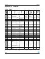
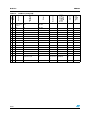
BOM list
Reference
Quantity
Index
Table 12.
BOM list
1
1
BT1
PCB mount NiMH
battery,4.8V 150mAh
THT
VARTA
55615604940
RS
422-400
2
1
BT2
BR2032H2A lithium
coincell,3V 190mAh
THT
Panasonic
BR2032/1GURS
RS
597-396
3
3
C1,C10,C11
100uF 25V electrolytic
THT 2.54mm pitch,
Diameter=7mm
4
1
C2
22 nF 25V ceramic
SMD 0805
5
1
C3
10uF 50V electrolytic
THT 2.54mm pitch,
Diameter=5mm
6
11
C4,C9,C27,C3
2,C5,C12,C19,
100 nF 25V ceramic
C24,C25,C30,
C33
SMD 0805
7
2
C6,C7
1uF 450V electrolytic
THT 3.5mm pitch,
Diameter 8mm
8
1
C8
47uF 25V
THT 2.54mm pitch,
Diameter=5mm
9
5
C13,C14,C20,
C23,C31
10nF 25V ceramic
SMD 0805
10
1
C15
1nF 50V ceramic
SMD 0805
11
3
C16,C17,C18
1uF 25V ceramic
SMD 0805
12
4
C21,C22,C28,
C29
15 pF 25V ceramic
SMD 0805
13
1
C26
33nF 25V ceramic
SMD 0805
14
1
DZ1
zener 9.1V 0.5W
SMD DO-213
Distrelec
601496
RS
269-451
15
1
DZ2
zener 10V 0.5W
SMD DO-213
16
2
D2,D8
STTH1L06
SMD SMA
ST
STTH1L06A
17
4
D3,D11,D12,D
13
LL4148 Small signal diode
SMD 1206
DIOTEC
SEMICONDU
CTOR
LL4148
18
1
D4
BAT49
SMD MELF
ST
TMBAT 49
19
2
D5,D6
GF1M Rectifier diode, 1A
1000V
SMD DO214
General
Semiconducto GF1M
r
20
1
D9
3mm red LED
THT
21
1
D10
IR Emitting Diode 5mm
THT
22
1
JA1, J6
5 way 2 row header,0.1in
pitch 7mm pin (10 PIN strip
line)
THT
23
2
JP1, SW2
2 way 1 row header,0.1in
pitch 7mm pin (2 PIN strip line
for jumper)
THT
28/35
VISHAY
TSAL6100
UM0402
24
2
J1,J2
1 pin header,0.1in pitch 7mm
pin
THT
25
2
J4,J5
DCT108 1:2500 12.5Ω 0.1%
100A CURRENT
TRANSFORMER
THT
OSWELL
(www.oswell.c
om.cn)
DCT108B
26
1
J7
LCD DE7936/V
THT
Display
Elektronik
GmbH
DE 7936/V
27
1
L1
Power-Use SMD Inductor
1MH
SMD
TDK
SLF10145T102MR29-PF
28
1
L2
jumper wire
29
1
L1 BC1
470uH 0.24A, Miniature axial
inductor
THT
Supplier's
ordering
code
Supplier
Manufacturer's
ordering code /
Orderable Part
Number
Manufacturer
Package
Value / Generic
Part Number
BOM list (continued)
Reference
Quantity
Index
Table 12.
BOM list
RS
240-545
BRIGT LED
ELECTRONIC
S CORP.
BPD-BQA314
(www.brightle
d.com.tw)
30
1
Q1
SILICON PHOTO DIODE
THT
31
2
Q2,Q3
BC847 NPN general purpose
transistors
SMD SOT23
32
1
RF1
10R 1W ROX1S metal oxide
film resistor
THT
Tyco
Electronics
Neohm
ROX1SJ10R
RS
214-0879
33
1
RV1
275V 8.6J SMD varistor
SMD DO214AB
EPCOS
B72650M271K72
Distrelec
730096
34
6
R1,R2,R29,R3
6,R38,R41
10kΩ
SMD 0805
35
1
R3
22EΩ
SMD 1206
BEYSCHLAG
MMA0204
Distrelec
713010
BEYSCHLAG
MMA0204
Distrelec
713153
36
1
R4
5KΩ
SMD 1206
37
2
R5,R7
0Ω
SMD 0805
38
1
R6
750Ω 1%
SMD 0805
39
4
R8,R13,R15,R
20
1kΩ 1%
SMD 0805
R9, R16
2.2Ω 1% Professional MELF
resistor
SMD minimelf 1206
40
41
4
R10, R17
no mounted
42
1
R11
2,2kΩ 1%
SMD 0805
43
2
R12,R37
1MΩ 1%
SMD 0805
44
2
R14,R18
2MΩ 1% Professional MELF
resistor
SMD minimelf 1206
45
1
R19
150kΩ
SMD 0805
46
2
R21,R22
270KΩ 1% Professional
MELF resistor
SMD minimelf 1206
BEYSCHLAG
MMA0204
Distrelec
713132
47
1
R23
200kΩ 1% Professional
MELF resistor
SMD minimelf 1206
BEYSCHLAG
MMA0204
Distrelec
713129
48
1
R24
470Ω 1% Professional MELF
resistor
SMD minimelf 1206
BEYSCHLAG
MMA0204
Distrelec
713066
29/35
BOM list
49
8
R25,R26,R27,
R28,R31,R32,
R33,R34
56kΩ
SMD 0805
50
1
R30
3kΩ
SMD 0805
51
1
R35
4.7kΩ
SMD 0805
52
1
R39
39Ω
SMD 1206
53
1
R40
220Ω
SMD 0805
54
1
SW1
6x6mm r/a tactile switch
THT
Tyco
8-1437565-5
55
1
U1
VIPER12
SMD SO8
ST
VIPer12AS - E
56
1
U2
L78L05AC
SMD SO8
ST
L78L05ACD13TR
57
1
U3
STPM14
SMD TSSOP20
ST
STPM14
58
1
U4
M95256
SMD SO8
ST
M95256MW6P
59
1
U5
M41T94
SMD SO16
ST
M41T94MQ6E
60
1
U7
74HC04
SMP SOP
ST
M74HC04M1R
Supplier's
ordering
code
Supplier
Manufacturer's
ordering code /
Orderable Part
Number
Manufacturer
Package
Value / Generic
Part Number
BOM list (continued)
Reference
Quantity
Index
Table 12.
UM0402
479-1520
RS
526-6154
61
1
X1
16 MHZ Resonator
THT
Murata
CSTLS16M0X55
RS
335026
62
1
Y1
4.194304 MHZ Quartz
THT
AURIS
HC-49/US SMD
Distrelec
226-1443
63
1
Y2
32.768 kHz Crystal
THT
C-MAC
MicroTechnolo XTAL002995
gy
64
1
U6
ST72F321BR6
SMD
ST
30/35
ST72F321BR6T6
RS
UM0402
Layout
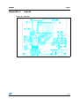
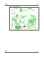
Appendix C
Layout
Figure 10. Top layer
31/35
Layout
UM0402
Figure 11. Bottom layer
32/35
UM0402
Layout
Figure 12. Components layer
33/35
Revision history
7
UM0402
Revision history
Table 13.
34/35
Document revision history
Date
Revision
17-Apr-2007
1
Changes
Initial release.
UM0402
Please Read Carefully:
Information in this document is provided solely in connection with ST products. STMicroelectronics NV and its subsidiaries (“ST”) reserve the
right to make changes, corrections, modifications or improvements, to this document, and the products and services described herein at any
time, without notice.
All ST products are sold pursuant to ST’s terms and conditions of sale.
Purchasers are solely responsible for the choice, selection and use of the ST products and services described herein, and ST assumes no
liability whatsoever relating to the choice, selection or use of the ST products and services described herein.
No license, express or implied, by estoppel or otherwise, to any intellectual property rights is granted under this document. If any part of this
document refers to any third party products or services it shall not be deemed a license grant by ST for the use of such third party products
or services, or any intellectual property contained therein or considered as a warranty covering the use in any manner whatsoever of such
third party products or services or any intellectual property contained therein.
UNLESS OTHERWISE SET FORTH IN ST’S TERMS AND CONDITIONS OF SALE ST DISCLAIMS ANY EXPRESS OR IMPLIED
WARRANTY WITH RESPECT TO THE USE AND/OR SALE OF ST PRODUCTS INCLUDING WITHOUT LIMITATION IMPLIED
WARRANTIES OF MERCHANTABILITY, FITNESS FOR A PARTICULAR PURPOSE (AND THEIR EQUIVALENTS UNDER THE LAWS
OF ANY JURISDICTION), OR INFRINGEMENT OF ANY PATENT, COPYRIGHT OR OTHER INTELLECTUAL PROPERTY RIGHT.
UNLESS EXPRESSLY APPROVED IN WRITING BY AN AUTHORIZED ST REPRESENTATIVE, ST PRODUCTS ARE NOT
RECOMMENDED, AUTHORIZED OR WARRANTED FOR USE IN MILITARY, AIR CRAFT, SPACE, LIFE SAVING, OR LIFE SUSTAINING
APPLICATIONS, NOR IN PRODUCTS OR SYSTEMS WHERE FAILURE OR MALFUNCTION MAY RESULT IN PERSONAL INJURY,
DEATH, OR SEVERE PROPERTY OR ENVIRONMENTAL DAMAGE. ST PRODUCTS WHICH ARE NOT SPECIFIED AS "AUTOMOTIVE
GRADE" MAY ONLY BE USED IN AUTOMOTIVE APPLICATIONS AT USER’S OWN RISK.
Resale of ST products with provisions different from the statements and/or technical features set forth in this document shall immediately void
any warranty granted by ST for the ST product or service described herein and shall not create or extend in any manner whatsoever, any
liability of ST.
ST and the ST logo are trademarks or registered trademarks of ST in various countries.
Information in this document supersedes and replaces all information previously supplied.
The ST logo is a registered trademark of STMicroelectronics. All other names are the property of their respective owners.
© 2007 STMicroelectronics - All rights reserved
STMicroelectronics group of companies
Australia - Belgium - Brazil - Canada - China - Czech Republic - Finland - France - Germany - Hong Kong - India - Israel - Italy - Japan Malaysia - Malta - Morocco - Singapore - Spain - Sweden - Switzerland - United Kingdom - United States of America
www.st.com
35/35