1
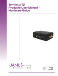
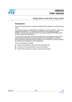
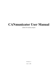
Terminus 400AP
Products User Manual –
Hardware Guide
This hardware guide applies to serial numbers
beginning with 03: 03-xxxxx
Bulletin
Revision
Date
JA07-UM-SN3
A00
30 May 2012
TABLE OF CONTENTS
TABLE OF CONTENTS and DISCLAIMER.............................................................................................................................. 2
400AP Open Platform General Description........................................................................................................................... 3
Plug-In Terminals
400AP Peripherals................................................................................................................................................................ 4-8
SDRAM Memory
NAND Flash Memory
SD Memory Card
RS-232 Serial Communications
RS-232 USART1 Connections
RS-232 DBGU Connections
RS-232 Transceiver Connections
RS-485 Serial Communications
RS485-USART2 Connections
USB Host Serial Communications
USB Device Serial Communications
Ethernet 10/100 PHY
Controller Area Network (CAN)
CAN0 Controller Connections
CAN0 Transceiver Connections
CAN1 Controller Connections
CAN1 Transceiver Connections
RTC
Accelerometer
Cellular Plug-In Terminal
Plug-In MODEM Connections........................................................................................................................................... 8-10
UART_ENABLE Truth Table
UART SUPPLY Truth Table
Enable VBUS
ON_OFF Truth Table
RESET Truth Table
PWRMON Truth Table
SERVICE Truth Table
GPS_RESET Truth Table
Monetary Buttons................................................................................................................................................................. 11
LEDs .................................................................................................................................................................................... 11
Red LEDs
Yellow LEDs
Green LEDs
Cellular RF Port - Coming Soon. ............................................................................................................................................ 12
GPS RF Port - Coming Soon. ................................................................................................................................................. 12
Front Panel - Coming Soon. ................................................................................................................................................... 12
Rear Panel - Coming Soon. ................................................................................................................................................... 12
20 Pin Header........................................................................................................................................................................ 12
Installing SIM Card
Samtec Part Numbers.......................................................................................................................................................... 14
Electrical Specifications.................................................................................................................................................. 15-16
Absolute Maximum Ratings
Recommended Operating Conditions
I/O Levels (3.3V CMOS)
I/O Levels (1.8V CMOS)
I/O Levels (RS-232 Transceiver)
I/O Levels (RS-485 Transceiver)
I/O Levels (CAN Transceiver)
Mechanical Specifications - Coming Soon............................................................................................................................ 17
Ordering Information............................................................................................................................................................. 18
Revision History.................................................................................................................................................................... 18
DISCLAIMER
The information contained in this document is the proprietary information of Connor-Winfield Corporation and its affiliates (Janus Remote Communication). The contents are confidential and any disclosure to
persons other than the officers, employees, agents or subcontractors of the owner or licensee of this document, without the prior written consent of Connor-Winfield, is strictly prohibited. Connor-Winfield
makes every effort to ensure the quality of the information it makes available. Notwithstanding the foregoing, Connor-Winfield does not make any warranty as to the information contained herein, and does
not accept any liability for any injury, loss or damage of any kind incurred by use of or reliance upon the information. Connor-Winfield disclaims any and all responsibility for the application of the devices
characterized in this document, and notes that the application of the device must comply with the safety standards of the applicable country, and where applicable, with the relevant wiring rules. ConnorWinfield reserves the right to make modifications, additions and deletions to this document due to typographical errors, inaccurate information, or improvements to programs and/or equipment at any time
and without notice. Such changes will, nevertheless be incorporated into new editions of this application note.
All rights reserved 2011 Connor-Winfield Corporation
Terminus 400AP User Guide JA07-UM
Page 2
Rev: A03
Date: 05/30/12
© Copyright 2012 Janus Remote Communications All Rights Reserved Specifications subject to change without notice
400AP Open Platform General Description
The 400AP Intelligent Terminus provides a complete wireless communication device with integrated ARM9™ processor,
expanded memory and cellular communication protocols to fit any application. The AMTEL ARM9™ processor has
a large support community available to reference while developing applications. Additionally, Janus has hardware/
software partners waiting to assist users in quickly getting your product to market. The Terminus 400AP allows users
the flexibility to choose OS and if users are looking for embedded Linux OS, we can show them how to set up Linux
toolchain to quickly compile a Linux Kernel and Filesystem so users are up and running in hours.
Power
SDRAM
NAND
Flash
MicroSD
Card
GPIO
400AP
Plug-In MODEM
(Cellular & GPS)
Wired Ethernet
802.3
AT91SAM9G20
RS-232
Serial Port
Accelerometer
RS-485
Serial Port
RS-232
Debug
CAN0
CAN1
USB
Host
RTC
Plug-In Terminals:
Cellular communication protocols for the Terminus 400AP are powered by Terminus Plug-In terminals. Plug-In
Terminus offer easy integration and interchangeability of communication protocols between GSM/GPRS, CDMA,
HSPA and more by combining full M2M functionality with the flexibility of a standard “plug-in” DIP design.
These terminals share the same mechanical footprint and offer users the ability to configure their applications
for communications via any cellular protocol. By using these modules to power the cellular technology of the
400AP, users can easily change cellular technology without having to change platforms. The 400AP provides one
platform that supports current cellular technology with the future in mind.
Terminus 400AP User Guide JA07-UM
Page 3
Rev: A03
Date: 05/30/12
© Copyright 2012 Janus Remote Communications All Rights Reserved Specifications subject to change without notice
400AP Peripherals:
The 400AP is loosely based on the Atmel AT91SAM9G20 reference design. The following section will describe the
connections of memory and peripherals as they pertain to the 400AP platform.
SDRAM Memory:
The 400AP includes a single chip of 64MB SDRAM and is connected to the External Bus Interface (EBI) of the
9G20 processor via a 16-bit data bus. For a complete description of the EBI and static memory controller refer to
the Atmel AT91SAM9G20 User Manual.
For a complete technical description of the SDRAM memory please refer to the Micron Data Sheet.
Micron Part Number: MT48H32M16LFB4-75 IT:C
NAND Flash Memory:
A single chip of 128MB bootable NAND flash is connected to the EBI of the 9G20 processor via an 8-bit data bus.
For a complete description of the EBI and NAND flash support refer to the Atmel AT91SAM9G20 User Manual.
For a complete technical description of the NAND flash memory please refer to the Micron Data Sheet.
Micron Part Number:
MT29F1G08ABBDAH4:D
SD Memory Card:
A micro SD memory card socket is connected to the MultiMedia Card Interface (MCI) of the 9G20 processor via
Slot A. Slot A can be used to boot an application from or be used to store application data. The MCI is complaint
with the SD Memory Card Specification V1.0
Terminus 400AP User Guide JA07-UM
Page 4
Rev: A03
Date: 05/30/12
© Copyright 2012 Janus Remote Communications All Rights Reserved Specifications subject to change without notice
400AP Peripherals continued:
RS-232 Serial Communications:
Two RS-232 serial ports are available on the 400AP. The 9G20 debug serial port is exposed externally via a DB9
connector on the front panel of the 400AP. This port can be used as a Universal Synchronous Asynchronous
Receiver Transceiver (USART) or as the serial interface to the Debug Unit (DBGU) of the 9G20 processor. The
debug USART is implemented with RX and TX signaling. The second RS-232 serial port is externally exposed via
the 20-pin locking connector on the rear panel of the 400AP and is connected to USART1 of the 9G20 processor.
USART1 is capable of using RTS/CTS hardware flow control. For a complete description of the DBGU and USART
functionality refer to the Atmel AT91SAM9G20 User Manual.
Both ports use the same RS-232 transceiver chip and can be simultaneous disabled by use of the FORCEON and
NFORCEOFF control inputs. For a complete description of this functionality please refer to the Texas Instrument
Data Sheet.
Texas Instrument Part Number: MAX3238
RS-232 USART1 Connections:
Pin Name
AT91SAM9G20
Function
Pin
400AP – Locking Header 2x10
Name
Function
PB6
PB7
PB28
PB29
TXD1
RXD1
RTS1
CTS1
RS232-TX
RS232-RX
RS232-RTS
RS232-CTS
12
14
16
18
Serial Data Output
Serial Data Input
Ready To Send Output
Clear To Send Input
RS-232 DBGU Connections:
Pin Name
AT91SAM9G20
Function
Pin
400AP – DB9
Name
Function
PB15
PB14
DTXD
DRXD
RS232-DTX
RS232-DRX
Serial Data Output
Serial Data Input
2
3
RS-232 Transceiver Connections:
Pin Name
AT91SAM9G20
Function
Pin
MAX3238
Name
Function
PA23
PA24
GPIO
GPIO
FORCEON
NFORCEOFF
Force On Input (Pulled-High)
Force Off Input (Pulled-High)
13
14
J1708 / RS-485 Serial Communications:
A single J1708 RS-485 serial port is available on the 400AP. The RS-485 serial port is externally exposed via the 20pin locking connector on the rear panel of the 400AP. The serial port is connected to USART2 of the 9G20 processor.
For a complete description of the USART and RS-485 functionality refer to the Atmel AT91SAM9G20 User Manual.
For a complete description of the RS-485 transceiver please refer to the Maxim Data Sheet.
Maxim Part Number: MAX13430E.
Figure 1 - Transceiver Configuration
Terminus 400AP User Guide JA07-UM
Page 5
Rev: A03
Date: 05/30/12
© Copyright 2012 Janus Remote Communications All Rights Reserved Specifications subject to change without notice
400AP Peripherals continued:
J1708 / RS-485 Serial Communications continued
RS-485 Connections:
AT91SAM9G20 Pin Name
Function
Pin
Name
MAX13430E
Function
PB8
PB9
Driver Output Enable
Receiver Output
TXD2 (Inverted)
RXD2
3
2
DE
RO
MAX13430E
Pin Name
Pin
400AP – Locking Header 2x10
Function
8
9
Serial Data I/O A
Serial Data I/O B
RS485A Serial Data I/O A
RS485B Serial Data I/O B
6
8
USB Host Serial Communications:
There are two USB host ports on the 400AP. Channel B - USB Host Port (UHP) controls the Janus Remote
Communications Plug-In cellular terminal. Channel A - USB Host Port (UHP) is externally exposed on the
front panel of the 400AP. For a complete description of the USB and UHP functionality refer to the Atmel
AT91SAM9G20 User Manual.
USB Device Serial Communications:
There is a single USB device port externally exposed on the front panel of the 400AP. The USB Device Port (UDP)
is compliant with the Universal Serial Bus (USB) V2.0 full-speed device specification. For a complete description
of the USB and UDP functionality refer to the Atmel AT91SAM9G20 User Manual.
Ethernet 10/100 PHY:
A physical layer transceiver for 100BASE-TX and 10BASE-T operations is available on the 400AP. The physical
layer fully complies with IEEE802.3/ IEEE802.3U 10BASE-T /100BASE-TX standards. The physical layer is
connected to the Ethernet 10/100 MAC of the 9G20 processor via an RMII interface. For a complete description
of the Ethernet 10/100 MAC refer to the Atmel AT91SAM9G20 User Manual.
For a complete technical description of the physical layer chip please refer to the Davicom Data Sheet.
Davicom Part Number: DM9161BIEP
Terminus 400AP User Guide JA07-UM
Page 6
Rev: A03
Date: 05/30/12
© Copyright 2012 Janus Remote Communications All Rights Reserved Specifications subject to change without notice
400AP Peripherals continued:
Controller Area Network (CAN):
Two stand-alone Controller Area Network (CAN) controllers/transceivers are available on the 400AP. The CAN
controllers comply with version 2.0B of the Controller Area Network specification. The CAN controllers are
connected via the SPI interface of the 9G20 processor. For a complete description of the SPI interface refer to the
Atmel AT91SAM9G20 User Manual.
For a complete technical description of the CAN controller and transceiver chip please refer to the NXP Data
Sheets.
Microchip Part Number:
MCP2515
NXP Part Number:
TJF1051
CAN0 Controller Connections:
AT91SAM9G20
Pin Name
Function
MCP2515
Pin
Name
Function
NRST
PA3
PA0
PA1
PA2
PB20
PB21
PB1
19
18
17
16
14
13
12
11
Reset
Chip Select
Serial Data Out
Serial Data In
Serial Clock
Interrupt
RXB0 Interrupt
RXB1 Interrupt
Reset
SPI0 – NPCS0
SPI0 – MISO
SPI0 – MOSI
SPI0 – SPCK
GPIO
GPIO
GPIO
RESET
CS
SO
SI
SCK
INT
RX0BF
RX1BF
CAN0 Transceiver Connections:
TJF1051
Pin Name
Function
400AP – Locking Header 2x10
Pin
Name
Function
7
6
7
9
TJF1051
AT91SAM9G20
8
PB13
CANH
CANL
S
CAN High-Level I/O
CAN Low-Level I/O
Silent Mode Enable
CANH0
CANL0
CAN High-Level I/O
CAN Low-Level I/O
GPIO
CAN1 Controller Connections:
AT91SAM9G20
Pin Name
Function
MCP2515
Pin
Name
Function
NRST
PC16
PA0
PA1
PA2
PB2
PB3
PB16
19
18
17
16
14
13
12
11
Reset
Chip Select
Serial Data Out
Serial Data In
Serial Clock
Interrupt
RXB0 Interrupt
RXB1 Interrupt
Reset
SPI0 – NPCS2
SPI0 – MISO
SPI0 – MOSI
SPI0 – SPCK
GPIO
GPIO
GPIO
RESET
CS
SO
SI
SCK
INT
RX0BF
RX1BF
CAN1 Transceiver Connections:
TJF1051
Pin
Name
Function
400AP – Locking Header 2x10
Pin
Name
Function
7
6
13
15
TJF1051
AT91SAM9G20
8
PB13
CANH
CANL
S
CAN High-Level I/O
CAN Low-Level I/O
Silent Mode Enable
CANH1
CANL1
CAN High-Level I/O
CAN Low-Level I/O
GPIO
Terminus 400AP User Guide JA07-UM
Page 7
Rev: A03
Date: 05/30/12
© Copyright 2012 Janus Remote Communications All Rights Reserved Specifications subject to change without notice
400AP Peripherals continued:
Real Time Clock (RTC):
A battery backed up RTC is available on the 400AP. The RTC has a built-in power-on reset controller that controls
the NRST input of the AT91SAM9G20 processor. The RTC is connected via the SPI interface of the 9G20
processor. For a complete description of the SPI interface refer to the Atmel AT91SAM9G20 User Manual.
For a complete technical description of the RTC please refer to the ST data sheet.
ST Part Number: M41T94
AT91SAM9G20 Pin Name
Function
Pin
NRST
Reset Input
PC17
SPI0 – NPCS3
PA0
SPI0 – MISO
PA1
SPI0 – MOSI
PA2
SPI0 – SPCK
PC18
GPIO
3
15
9
12
10
14
5
M41T94
Name
Function
RSTPower-on Reset OD output
CS
Chip Select
SO
Serial Data Out
SI
Serial Data In
SCK
Serial Clock
IRQ Interrupt Output
MR400AP External Reset Button
RTC Backup Battery:
A CR1220 primary Lithium coin cell is supplied with the 400AP. The battery socket has been protected from
reverse battery installation. During reverse battery installation the RTC will not be able to maintain time when
power is removed.
Accelerometer:
A three axis digital accelerometer is available on the 400AP. The SPI / I2C interface of the accelerometer has been
connected via 9G20 GPIO.
For a complete technical description of the accelerometer please refer to the Bosch data sheet.
ST Part Number: BMA222
AT91SAM9G20 Pin Name
Function
Pin
PC19
PC20
PC21
PC22
PC23
PC24
PC25
GPIO
GPIO
GPIO
GPIO
GPIO
GPIO
GPIO 2
12
1
10
11
6
1
BMA222
Name
Function
SDA/SDI
SPI Data Input, I2C Data
SCL/SCK
Serial Clock Input
SA0/SDO
SPI Data Output, I2C A0
CS
Chip Select
PS
Protocol Select
INT2 Interrupt Output 2
INT1 Interrupt Output 1
Cellular Plug-In Terminal:
A socket for a Janus Remote Communication Plug-In terminal is available on the 400AP. There is a GSM/GPRS,
CDMA/1xRTT, and HSPA version of the Plug-In terminal available. All required I/O to control the Plug-In terminal
including USB; USART and GPIO’s are described below. For a complete technical description of the Plug-In
Terminus, please refer to the Janus Remote Communications User Guide.
Janus Remote Communications Part Numbers: GSM865CF, CDMA864CF and HSPA910CF
Terminus 400AP User Guide JA07-UM
Page 8
Rev: A03
Date: 05/30/12
© Copyright 2012 Janus Remote Communications All Rights Reserved Specifications subject to change without notice
Plug-In MODEM Connections:
AT91SAM9G20
Pin Name Function
Plug-In MODEM
Pin
Name
Function
PC15
PC8
PC9
PB31
PC12
PC10
PB11
PB10
PA30
PA31
PB4
PB5
PB26
PB27
PB22
PB24
PB23
PB25
HDPB
HDMB
3
19
20
18
17
35
34
33
13
14
9
4
11
6
5
10
8
7
28
27
GPIO
GPIO
GPIO
GPIO
GPIO
GPIO
RXD3
TXD3
RXD4
TXD4
TXD0
RXD0
RTS0
CTS0
DSR0
DTR0
DCD0
RI0
USB Data +
USB Data -
ENABLE SUPPLY
ON_OFF
RESET
PWRMON
SERVICE
GPS_RESET
GPS_TX
GPS_RX
TRACE_TX
TRACE_RX
TXD
RXD
RTS
CTS
DSR
DTR
DCD
RING
USB_D+
USB_D-
Note
Plug-In Enable Input
ON OFF Toggle Input
Cellular Reset Input
Power Monitor Output
Service Input
MS20 GPS Reset Input
MS20 NMEA TXD Output
MS20 NMEA RXD Input
Trace Serial Port – TXD Output
Trace Serial Port – RXD Input
DCE Serial Port – TXD Input
DCE Serial Port – RXD Output
DCE Serial Port – RTS Input
DCE Serial Port – CTS Output
DCE Serial Port – DSR Output
DCE Serial Port – DTR Input
DCE Serial Port – DCD Output
DCE Serial Port – RING Output
USB D+
USB D-
1
1
1
1
1
1
1
1
1
1
Notes:
1) Digital I/O is level converted to match I/O levels between the AT91SAM9G20 and the Plug-In MODEM. Level converted outputs from the
AT91SAM9G20 can be set High-Z by use of UART_ENABLE input.
UART_ENABLE Truth Table:
UART_ENABLE (PB30)
Function
0
1
AT91SAM9G20 digital outputs driving into Plug-In terminal are enabled. This state
should be entered when the Plug-In terminal is powered on.
AT91SAM9G20 digital outputs driving into Plug-In terminal are set to High-Z. This
state should be entered when the Plug-In terminal is powered off.
ENABLE SUPPLY Truth Table:
ENABLE SUPPLY (PC15)
Function
Plug-In terminal power supply is enabled and supplying power to the Plug-In terminal.
Plug-In terminal power supply is disabled.
0
1
ENABLE VBUS (PC3)
ENABLE VBUS (PC3)
Function
Plug-In terminal VBUS input is set to ground.
Plug-In terminal VBUS input is set to 5Vdc.
0
1
Terminus 400AP User Guide JA07-UM
Page 9
Rev: A03
Date: 05/30/12
© Copyright 2012 Janus Remote Communications All Rights Reserved Specifications subject to change without notice
Plug-In MODEM Connections continued:
ON_OFF Truth Table:
ON_OFF (PC8)
Function
0
1
Run state. Input should remain in this state after the Plug-In terminal has been turned
On or Off.
Toggle state. Input should remain in this state for a specified amount of time in order
to turn On or Off the Plug-In terminal.
Hold time to turn Plug-In terminal On: > 1s
Hold time to turn Plug-In terminal Off: > 2s
RESET Truth Table:
RESET (PC9)
Function
0
1
Run state. Input should remain in this state when Plug-In terminal is operational.
Reset State.
Hold time to reset Plug-In terminal: > 200ms
PWRMON Truth Table:
PWRMON (PB31)
Function
Plug-In terminal is in an On State.
Plug-In terminal is in an Off State.
0
1
SERVICE Truth Table:
SERVICE (PC12)
Function
0
1
SERVICE state is disabled.
SERVICE state is enabled; GSM400AP models can have GSM radio firmware
uploaded via TRACE serial port.
Note: Applies to GSM400AP models only
GPS_RESET Truth Table:
GPS_RESET (PC10)
Function
0
1
Run state. Input should remain in this state when MS20 GPS receiver is operational.
MS20 GPS Receiver Reset State.
Hold time to reset MS20 GPS receiver: > 1ms
Note: Applies to GSM400AP V1.00 model only
Terminus 400AP User Guide JA07-UM
Page 10
Rev: A03
Date: 05/30/12
© Copyright 2012 Janus Remote Communications All Rights Reserved Specifications subject to change without notice
Plug-In MODEM Connections continued:
On power up the Plug-In terminal is in an off state. To turn on the Plug-In terminal the following steps must be followed.
1. Enable Plug-In terminal power supply.
PC15 = Logic Low
2. Clear Cellular Reset.
PC9 = Logic Low
3. High-Z all digital outputs driving into the Plug-In terminal.
PB30 = Logic High
4. For GSM400AP models disable Service mode.
PC12 = Logic Low
5. For GSM400AP V1.00 models clear MS20 GPS receiver reset.
PC10 = Logic Low
6. Set ON_OFF signal
PC8 = Logic High
7. Wait at least 3 seconds
8. Clear ON_OFF signal
PC8 = Logic Low
9. Read PWRMON input to determine if the Plug-In MODEM is on.
PB31 = = Logic Low
10. Enable USART.
PB30 = Logic Low
At this time the Plug-In terminal is on and AT commands can be sent via USART0. CDMA and HSPA 400AP
models can also use the AT command virtual serial port exposed via the USB port.
To turn off the Plug-In terminal the following steps must be followed.
1. High-Z all digital outputs driving into the Plug-In terminal.
PB30 = Logic High
2. Set ON_OFF signal
PC8 = Logic High
3. Wait at least 3 second
4. Clear ON_OFF signal
PC8 = Logic Low
5. Read PWRMON input to determine if the Plug-In terminal is on.
PB31 = = Logic High
At this point the Plug-In terminal is turned off.
Terminus 400AP User Guide JA07-UM
Page 11
Rev: A03
Date: 05/30/12
© Copyright 2012 Janus Remote Communications All Rights Reserved Specifications subject to change without notice
Momentary Buttons:
Reset Button: The Reset button is connected to the reset controller of the 400AP. When pressed and released the
400AP is reset.
Mode Button: The Mode button is used to place the 400AP into different operational modes during boot.
After boot, the mode button is available to the Application via 9G2O GPI0 PB18.
Mode
400AP Operation StateMode Entry Conditions
Normal Run Mode
400AP powered.
1.Apply power to 400AP or depress
After reset is released, the red light Reset Button
will illuminate.
2.Mode Button is not pressed
Application executes from first bootable
media found.
Note: If no bootable media is found
the 9G20 will boot into SAM-BA mode.
The green LED will not illuminate in this case.
SAM-BA Mode
400AP powered.
9G20 boots into SAM-BA mode and
green LED illuminates.
Note: Using this method to enter SAM-BA mode
is supported when using the factory-supplied
bootloader that evaluates the Mode button during
boot. If NAND Flash has been erased, this
functionality will not exist. The 400AP application
note Uploading Files into Flash explains
how to write the bootloader to flash..
Application 400AP is in Normal Run Mode.
Interrupt Mode
9G20 GPIO PB18 is set logic high when
Mode button is pressed. Note: The 400AP response to the mode
button is defined by the application
that was executed during boot.
1.Press Mode button
2.Apply power to 400AP or depress Reset Button
3.Depress Mode after Green LED illuminates
1.400AP is in Normal Run Mode
2.Press Mode button
LED’s:
Red LED: The Red LED is connected to GPIO PB12 of the 9G20 processor. This LED is on by
default unless the application defines its state.
Red LED State
400AP Operation Mode
Permanently On - during boot
Application defined after boot
400AP is powered
Booted into application which controls LED state
Yellow LED:The yellow LED indicates the Plug-in Terminal operation status.
Yellow LED State
400AP Operation State
Permanently Off
Permanently On
Fast Blinking (0.5 sec on / 0.5 sec off)
Slow Blinking (0.3 sec on / 2.7 sec off)
Cellular radio is off
A call is active
Net search / not registered / turning off
Registered, full service
Green LED:The green LED is connected to GPIO PB17 of the 9G20 processor. This LED is off by
default unless the application defines its state.
Green LED State
Permanently Off – during boot
Permanently On – during boot
Application defined – after boot
400AP Operation State
Booting into application
Entered SAMBA Mode
Booted into application which controls LED state
Terminus 400AP User Guide JA07-UM
Page 12
Rev: A03
Date: 05/30/12
© Copyright 2012 Janus Remote Communications All Rights Reserved Specifications subject to change without notice
Cellular RF Port:
SMA - FEMALE
Pin
Description
Center PinCellular Signal
Outer ConductorSIGNAL Ground
For Cellular RF Port details, view the Plug-In Terminus Manual as reference.
GPS RF Port:
MCX - FEMALE
Pin
Description
Center PinGPS Signal, 3.7 Vdc nominal supplied from Terminus to power active antenna.
Outer Conductor
Signal ground
Note: GPS Antenna Interface only available by option, otherwise not populated.
For GPS RF Port details, view Plug-In Terminus User Manual as reference
Front Panel:
Rear Panel:
Terminus 400AP User Guide JA07-UM
Page 13
Rev: A03
Date: 05/30/12
© Copyright 2012 Janus Remote Communications All Rights Reserved Specifications subject to change without notice
20 Pin Header
PIN
Description
Direction
LEVEL
1
2
3
4
5
6
7
8
9
10
11
12
13
14
15
16
17
18
19
20
9G20 GPIO (PC0)
9G20 GPIO (PA5)
9G20 GPIO (PC1)
9G20 GPIO (PB19)
GND
RS485_A
CAN0_HI
RS485_B
CAN0_LO
GND
GND
RS232 TX
CAN1_HI
RS232 RX
CAN1_LO
RS232 RTS
Enable
RS232 CTS
VIN
GND
IN / BI-DIR
BI-DIR
IN / BI-DIR
BI-DIR
N/A
BI-DIR
BI-DIR
BI-DIR
BI-DIR
N/A
N/A
OUTPUT
BI-DIR
INPUT
BI-DIR
OUTPUT
IN
INPUT
IN
N/A
Analog / 3.3v CMOS
3.3v CMOS
Analog / 3.3v CMOS
3.3v CMOS
N/A
RS-485
CAN
RS-485
CAN
N/A
N/A
RS-232
CAN
RS-232
CAN
RS-232
12.0v (Active High)
RS-232
12.0v
N/A
Samtac Part Numbers:
Housing:
IPD1-10-D-K
Contacts: CC79L-2024-01-L
Janus Store Part Number:
XT- 478-G XT-479-G
Installing SIM Card into the GSM/HSPA 400AP
Step 1. To access the 400AP board, remove the four TX-10 screws from the ruggedized aluminum enclosure. These screws are
located on the back panel of the 400AP where the DB9 and lock header are located.
Terminus 400AP User Guide JA07-UM
conntinued…
Page 14
Rev: A03
Date: 05/30/12
© Copyright 2012 Janus Remote Communications All Rights Reserved Specifications subject to change without notice
Installing SIM Card into the GSM/ HSPA 400AP continued
Step 2. Slide out the back panel which will include the 400AP board.
Step 3. Locate the SIM Card slot on top of the Terminus Plug-In board.
Step 4. To insert the SIM card in the SIM card slot, slide the top of the cover back to unlock. Insert the SIM card in the cover slot
and close. Slide back to original position to lock in place.
Slide back to unlock
Step 5. Slide the back panel and 400AP board into the aluminum enclosure. Replace the four TX-10 screws and tighten them
back on to enclosure.
Terminus 400AP User Guide JA07-UM
Page 15
Rev: A03
Date: 05/30/12
© Copyright 2012 Janus Remote Communications All Rights Reserved Specifications subject to change without notice
Electrical Specifications:
Absolute Maximum Ratings:
Parameter
Minimum
Nominal
Maximum
Unit
Note
-40
-36
-0.3
-0.3
-25
-8
-42
-0.3
-
-
-
-
-
-
-
-
85
36
3.6
2.1
25
13
42
3.6
°C
Volt
Volt
Volt
Volt
Volt
Volt
Volt
1
1,2
1
1
1
1
1
1
Storage Temperature
Supply (Supply & Enable Input)
VIN (Digital Inputs 3.3V CMOS)
VIN (Digital Inputs 1.8V CMOS)
VIN (RS-232 Inputs)
VIN (RS-485 Inputs)
VIN (CAN Inputs)
VIN (USB Inputs)
Notes:
1) Operation of the device at these or any other conditions beyond those listed under Recommended Operating Conditions is not implied. Exposure
to Absolute Maximum Rating conditions for extended periods of time may affect device reliability.
2) The supply inputs are protected from reverse voltage and transients beyond the Recommended Operating Conditions. If transients persist the
supply will be latched in a disable state. Once disabled the supply will need to be cycled off and on to reset.
Recommended Operating Conditions:
Parameter
Operational Temperature:
GSM400AP V1.1
GSM400AP V2.0
CDMA400AP
HSPA400AP
Supply (Supply & Enable Input)
Peak Supply Power
Average Supply Current
Minimum
Nominal
Maximum
-20
-40
-30
-30
7
-
-
-
-
-
-
-
-
-
65
85
80
80
26
12.5
TBD
Unit
Note
°C
Volt
Watts
Amp
1
2
Notes:
1)Peak Supply Power specification is stated as the minimum amount of power the external power supply must supply during the TX burst of the
embedded cellular radio. Please refer to the Plug-In User Manual for power supply characteristics of the embedded Plug-In Module embedded in
the 400AP terminal. Plug-In User Manual can be downloaded at http://www.janus-rc.com/terminuscf.html
2)Average Supply Current specification is stated as the maximum average current the 400AP terminal can draw while maintaining junction
temperatures within the internal power supply IC’s specifications. It is the applications responsibility to maintain operation within this limit to
maintain reliable operation over the life of this terminal product.
I/O Levels (3.3V CMOS)
Parameter
Input Voltage Low - Vil
Input Voltage High - Vih
Output Voltage Low – Vol
-
Output Voltage High – Voh
Output Current - Io
Pull-up Resistance - RPULLUP
Minimum
Nominal
Maximum
Unit
-0.3
2
-
2.9
-
40
-
-
0.4
-
-
75
0.8
3.6
Volt
-
8
190
Volt
Volt
1
Volt
mA
kohm
Note
1
Notes:
1) Test conditions: Max Io.
I/O Levels (RS-232 Transceiver)
Please refer to the Texas Instruments data sheet for a complete listing of specifications for the RS-232 transceiver
used in the 400AP terminal.
Texas Instrument Part Number: MAX3238
Terminus 400AP User Guide JA07-UM
Page 16
Rev: A03
Date: 05/30/12
© Copyright 2012 Janus Remote Communications All Rights Reserved Specifications subject to change without notice
Electrical Specifications continued:
I/O Levels (RS-485 Transceiver)
Please refer to the Microchip data sheet for a complete listing of specifications for the RS-485 transceiver used in
the 400AP terminal.
Maxim Part Number:
MAX13430
I/O Levels (CAN Transceiver)
Please refer to the NXP data sheet for a complete listing of specifications for the CAN transceiver used in the
400AP terminal.
NXP Part Number:
TJF1051 T/3
Mechanical Specifications:
Terminus 400AP User Guide JA07-UM
Page 17
Rev: A03
Date: 05/30/12
© Copyright 2012 Janus Remote Communications All Rights Reserved Specifications subject to change without notice
Terminus 400AP
Products User Manual –
Hardware Guide
Ordering Information
Ordering Information
Description
GSM400AP v1.00
GSM400AP v2.00
CDMA400AP v2.00
CDMA400AP v3.00
HSPA400AP v1.00
GSM with GPS
GSM without GPS
CMDA – Sprint Certified
CDMA – Verizon Certification Pending
HSPA
Revision History
Revision Revision Date
Note
A00
Advanced Release - User Manual
05/30/12
Division of The Connor-Winfield Corporation
2111 Comprehensive Drive • Aurora, Illinois 60505
630.499.2121 • Fax: 630.851.5040
www.janus-rc.com
Janus Remote Communications Europe
Bay 143
Shannon Industrial Estate
Shannon, Co. Clare, Ireland
Phone: +353 61 475 666