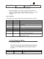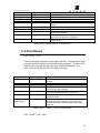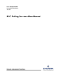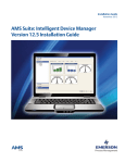
1
DeltaV ROConnect
Version 1.1
User Manual
August 13, 2009
ROConnect User Manual
Disclaimers
©MYNAH Technologies 2007. All rights reserved.
Designs are marks of MYNAH Technologies; Emerson Process Management,
DeltaV, and the DeltaV design are marks of Emerson Process Management. All
other marks are property of their respective owners.
While this information is presented in good faith and believed to be accurate,
MYNAH Technologies does not guarantee satisfactory results from reliance upon
such information. Nothing contained herein is to be construed as a warranty or
guarantee, express or implied, regarding the performance, merchantability, fitness
or any other matter with respect to the products, nor as a recommendation to use
any product or process in conflict with any patent. Mynah Technologies reserves the
right, without notice, to alter or improve the designs or specifications of the products
described herein. All sales are governed by MYNAH Technologies’ terms and
conditions, which are available on request.
i
ROConnect User Manual
Table of Contents
1
OVERVIEW ................................................................ ERROR! BOOKMARK NOT DEFINED.
DeltaV and ROConnect Integration ................................................................................................................. 6
Limitations ...................................................................................................................................................... 8
Applications .................................................................................................................................................... 8
RocConnect Communication Suite ...................................................................................................................9
DeltaV RocConnect Configuration Utility......................................................................................................9
DeltaV App Station Module Templates ..........................................................................................................10
2
THE MAIN WINDOW ............................................................................................................ 11
3
BUILDING A CONFIGURATION ......................................................................................... 12
Networks ...................................................................................................................................................... 12
Scan Threads ................................................................................................................................................. 14
Areas............................................................................................................................................................. 15
Devices ......................................................................................................................................................... 15
Collections .................................................................................................................................................... 19
Points............................................................................................................................................................ 19
Point Parameter............................................................................................................................................ 21
Historian ....................................................................................................................................................... 21
4
EXPORTING THE CONFIGURATION ................................................................................ 22
Name Conflicts .................................................................................................................................................22
5
THE BANDWIDTH REPORT ............................................................................................... 23
6
IMPORTING THE CONFIGURATION ................................................................................ 24
7
THE IMPORTED ELEMENTS .............................................................................................. 25
8
ASSIGNING MODULES AND EVENTS ............................................................................... 25
ii
ROConnect User Manual
Using the Function Blocks ............................................................................................................................. 27
Point and Parameter Function Blocks..............................................................................................................28
ROC and History Function Blocks .....................................................................................................................29
Network and Scan Thread Function Blocks .....................................................................................................31
9
FUNCTION BLOCK QUICK REFERENCE .......................................................................... 33
Imported Areas, Modules and Function Blocks ............................................................................................. 33
Configuration Blocks ..................................................................................................................................... 39
ROC_SCAN_INTERVAL......................................................................................................................................39
ROC_UNIT_LOGON ..........................................................................................................................................40
ROC_HISTORY ..................................................................................................................................................41
Point Parameter Blocks ................................................................................................................................. 41
Point Blocks .................................................................................................................................................. 42
Index of Tables
Table 1 - Interval Parameters
Table 2–ROC_NETWORK_CFG Function Block
Table 3–ROC_SCAN-INTERBAL Function Block
Table 4–ROC_UNIT_LOGON Function Block
Table 5–ROC_HISTORY Function Block
Table 6–ROC_PARAM_UINT8 Function Block
Table 7–ROC_<POINT_TYPE> Function Block
15
39
40
41
41
42
42
Index of Figures
Figure 1 – DeltaV ROConnect Integration Architecture
Figure 2 – DeltaV ROConnect Architecture and Applications
Figure 3 - The Main Window
Figure 4 - Network Properties: Misc
Figure 5- Network Properties: Addressing
Figure 6- Network Properties: Time Sync
Figure 7- Scan Thread Properties
iii
8
9
11
12
13
14
15
ROConnect User Manual
Figure 8- Area Properties
Figure 9- New ROC Source
Figure 10- ROC Device Properties: Misc
Figure 11- ROC Device Properties: Address
Figure 12- ROC Device Properties: Data Source
Figure 13- ROC Device Properties: Time Sync
Figure 14- ROC Device Properties: Retries
Figure 15- Collection Properties
Figure 16- Add Point
Figure 17- Point Properties
Figure 18- Point Parameter Properties
Figure 19- Historian Properties
Figure 20- Name Conflicts
Figure 21- Bandwidth Report
Figure 22– Imported Configuration
Figure 23– Modules and Events Assigned
Figure 24– Module A2G2_COL001
Figure 25– ROC Function Block
Figure 26– History Function Block
Figure 27– Network and Scan Thread Function Blocks
Figure 28– Control Strategies Areas
Figure 29– ROC_NETWORKS Area
Figure 30– Modules for each ROC
Figure 31– Function Blocks Defining each ROC
Figure 32– Point Type Function Blocks and Parameter Function Blocks
15
16
17
17
18
18
19
19
20
20
21
22
23
24
24
27
29
30
31
32
34
35
36
37
38
iv
ROConnect User Manual
1. Introduction
1.0. Scope
This document is the User Manual for the ROC communications interface application (RocConnect)
for the Emerson Process Management (EPM) DeltaV AppStation or ProPlus. It provides
information required to install, configure, and maintain the interface. The reader should be familiar
with EPM’s DeltaV modules and ROC objects.
The section Document Format briefly describes the contents of each section of this manual. System
Specifications outlines hardware and software requirements for the Ethernet/IP Driver firmware.
1.1. Document Format
This document is organized as follows:
Introduction
Describes the scope and purpose of this document.
Theory of Operation
Provides a general functional overview of the ROC
communications Driver.
DeltaV serial card Configuration
Describes procedures and guidelines for configuring
and importing the DeltaV modules.
ROC network configuration
Describes ROC devices in the network
configuration.
Operational Check
Provides tips and assistance to ensure the ROC
connection is properly setup and configured.
Technical Support
Describes who to call if you need assistance.
1.2. System Specifications
The following table lists the minimum system requirements for the Ethernet/IP Driver:
RocConnect Driver
System DLL for RocConnect
RocExplorer Utility
Windows PC resident configuration utility.
Protocol Compatibility
DeltaV ROC Interface Function Blocks
ROC Plus Protocol Specifications Manual
(d301180x012.pdf)
ROC Polling Service User Manual
(d301229x012.pdf)
Software Requirements
5
DeltaV System Software (Release 6.3 or later)
installed on a hardware-appropriate Windows
ROConnect User Manual
workstation configured as a ProfessionalPlus for
DeltaV
Minimum DeltaV Hardware
Requirements
Network Hardware
Requirements
DeltaV AppStation or ProPlus
ROC Controller(s), ROC Gateway Controller(s) or
field server(s)
Multiport 10/100BaseT Switch connected to ROC
network, not shared with DeltaV Control Network.
2. Theory of Operation
The ROConnect provides a native integration of ROC809 point data into DeltaV
function blocks. The product provides a complete integration application and
includes:
o
Intuitive ROConnect configuration utility that allows the user to browse
ROC809 data and select points or values that will be integrated with DeltaV.
o
Auto-generation of DeltaV function block configuration using the ROConnect
Utility’s FHX file generation capability.
o
Scheduling, and storing of ROC Electronic Flow Measurement (EFM) files for
custody transfer applications. Conversion of EFM data to Coastal Flow and PGas files can also be automatically scheduled.
o
Time synchronization control of the ROCs with the DeltaV host time clock.
o
All data and functions can be read and controlled via an OPC v2.0 Server
interface.
2.0. Prerequisites
o
The ROConnect Suite must be installed on either a DeltaV Professional Plus or
Application workstation. DeltaV software v7.2 or later is required.
o
2.1. DeltaV and ROConnect Integration
DeltaV ROConnect 1.1 provides a native integration of ROC809 point data into
DeltaV function blocks. The ROConnect Application can be used in systems with or
without DeltaV Controllers. The DeltaV and ROC Integration is a “true” integration,
meaning it is not an OPC interface, and mapping is not required. The application
allows various communications: hard-wires, wireless, and dialup. It also supports
HART pass-through for AMS interfaces. The application can read ROC EFM data for
storage and conversion to Coastal Flow and PGAS custody transfer file formats.
Additionally, the ROConnect Application supports all ROC809 point types, data
tables, and user-defined data types. Data from custom ROC firmware applications
(like the Danload 8000) can also be integrated with DeltaV using the ROConnect
application.
6
ROConnect User Manual
7
ROConnect User Manual
2.2.
2.3.
2.4.
2.5.
2.6.
2.7.
Figure 1 – DeltaV ROConnect Integration Architecture
2.8. Limitations
ROConnect does not allow configuration of ROC devices. Users will need to use the
ROCLink800 (RL800) application to configure the ROCs the same as any other
installation. Additionally, ROConnect only supports ROCPlus protocol and does not
currently support ROC protocol.
2.9. Applications
ROConnect allows seamless integration of process plants controlled by the DeltaV
Process System with wellhead and pipelines controlled with ROCs. It allows
connectivity of Inside Battery Limit (ISBL) Systems with Outside Battery Limit (OSBL)
Controllers. With its tight integration with DeltaV, users may want to consider ROCs for
applications normally served with PLCs. The application functions through native
DeltaV function blocks (no OPC mapping). ROCPlus Network Integration uses a third
NIC in an App Station. It provides a complete solution for integration of ROC Point, and
Electronic Flow Measurement History data.
The ROConnect Application has three functional parts as shown in Figure 2.
8
ROConnect User Manual
3.
Figure 2 – DeltaV ROConnect Architecture and Applications
RocConnect Communication Suite
ROConnect uses ROCPlus Protocol, handles poling of individual scan threads, and
passes data to DeltaV App Station Modules and OPC Server. The application reads
EFM Reports and writes to MS Access databases. It converts EFM data to Coastal Flow
and PGAS report formats. It allows for time synchronization of ROCs with DeltaV
Systems.
DeltaV RocConnect Configuration Utility
The DeltaV ROConnect Configuration allows users to configure all DeltaV Modules. It
reads ROCLink 800 databases or reads directly from the ROCs via a network. With the
configuration utility, users can browse to data of interest and configure scan threads.
Users can export DeltaV function block definitions to .FHX files. Users can also
schedule network time synchronization. Configuration files are saved in XML.
9
ROConnect User Manual
DeltaV App Station Module Templates
DeltaV App Station Module Templates are provided to allow custom modules for
integration of ROC data. This provides secure, tight integration with ROC. The
templates are supported in DeltaV version 7.2 or greater.
10
ROConnect User Manual
4. 2The Main Window
The main window of the application (Figure 3) is divided into two panes. On the left is a
tree view which organizes all of the items in the configuration. On the right is a listing of
properties for the currently selected item.
The toolbar along the top allows you to create, save and open configuration files.
Buttons for creating and deleting configuration items are also found in the toolbar.
Figure 3 - The Main Window
11
ROConnect User Manual
4.0.
5. 3Building a Configuration
Items are added to a configuration either by right-clicking on the left pane of the main
window, selecting the item to add from the Edit menu, or clicking on the item to add on
the toolbar. Items are added as children to the currently selected item. Only items
which are valid children of the selected item will therefore be available for addition. You
can modify the properties of an item in the tree by double-clicking on it or by selecting
Edit Item from either the item’s context menu or the Edit menu.
5.0. Networks
Each configuration must start with a network item. The network item is used to specify
which network adapter should be used to communicate with the ROCs. It also holds
some global information that applies to all ROCs. A network can be added by rightclicking the empty region of the left pane, selecting New Network from the Edit menu or
clicking on the network button on the toolbar.
When a new network is added, you will be presented with the dialog show in Figure 4.
On this tab of the dialog, a unique name must be given to the network. This name must
be a valid DeltaV identifier (only capital letters, number, and underscores are allowed
with a maximum length of 16 characters).
Figure 4 - Network Properties: Misc
12
ROConnect User Manual
On the addressing tab (Figure 5), the ROC group and unit address of the host machine
(the application station) must be entered. Additionally, the IP address assigned to the
network card that should be used to communicate with the ROCs must be specified. If
ROC Explorer is being run on the host machine, then its adapters can be selected from
the list.
Figure 5- Network Properties: Addressing
The Time Sync tab (Figure 6) is used to configure time synchronization. Max Average
Latency and Max Latency Variance specify preconditions that must be met for time
synchronization to proceed. The scanner will make one or more network latency
sensing reads from the ROC before attempting time synchronization. If the average of
latency is greater than Max Average Latency or the standard deviation is greater than
Max Latency Variance then time synchronization will not be performed. If
synchronization does proceed, then Allowed Error specifies the maximum allowed
difference between the host and ROC times after synchronization takes place for the
synchronization to be considered successful. If Auto Sync Enabled is checked, then
synchronization will be performed whenever the selected scan thread runs.
If auto synchronization is used, you should attempt to assign it to a scan thread which
runs when no other threads are running, and use that thread only for time
synchronization. If other threads are running during time synchronization, this can
cause fluctuations in the network latency, which will negatively affect the precision of the
synchronization.
13
ROConnect User Manual
Figure 6- Network Properties: Time Sync
5.1. Scan Threads
Scan threads are defined intervals or schedules at which work is done by the scanner.
At least one scan thread must be created per network for any work to be accomplished.
A scan thread can be added by right-clicking a network in the left pane, selecting New
Scan Thread from the Edit menu or clicking on the scan thread button on the toolbar.
When a new scan thread is created, you will be presented with the dialog shown in
Figure 7. Each scan thread must be given a unique name that is a valid DeltaV
identifier. The type of interval must also be chosen. Depending upon the selected
interval type there will be other parameters needed to further define the interval. These
parameters are described in Table 1. The Secondary Interval parameter available to
some types is a higher rate scan that can be enabled on a per function block basis in
DeltaV. This is intended to be used as a troubleshooting feature.
14
ROConnect User Manual
Figure 7- Scan Thread Properties
Type
100 MS
Seconds
Hours
Days
Parameter 1
Number of 100 MS ticks
Number of seconds
Number of hours
Number of days
Parameter 2
The minute in the hour at
which to trigger
The hour in the day at
which to trigger
Aperiodic
Parameter 3
Secondary interval (MS)
Secondary interval (MS)
Secondary interval (MS)
Table 1 - Interval Parameters
5.2. Areas
Areas translate directly to DeltaV areas. They are provided as both an organizational
tool, and to allow an efficient way to assign events to different stations. An area can be
added by right-clicking a network in the left pane, selecting New Area from the Edit
menu or clicking on the area button on the toolbar.
When a new area is created, you will be presented with the dialog shown in Figure 8.
Each area must be given a unique name that is a valid DeltaV identifier.
Figure 8- Area Properties
5.3. Devices
15
ROConnect User Manual
Devices represent the physical ROCs the scanner will be connecting to. A device can
be added by right-clicking an area in the left pane, selecting New Device from the Edit
menu or clicking on the device button on the toolbar.
When a new device is added, you will first be presented with the dialog shown in Figure
9. This dialog allows you to select the data source that ROC Explorer will use to limit
configuration options to only a valid set of points.
The default option is to acquire this data from an offline database (.800 file) generated
by ROCLINK800. For this option you must supply the .800 filename and associated
group security file (this should be the ROCLINK.mdw file in the ROCLINK800 program
folder).
Another option is to pull the data directly from an online ROC. This option is only
recommended if you have a low-latency, high-speed connection to the ROC as it can
take a long time to retrieve the configuration. If this option is selected you must provide
the IP address and port number used to access the ROC; the ROC group and unit
address; and the user ID and password used to log in.
If neither of these options is feasible, select “None” for the data source. You will have to
manually enter additional information and ensure your point selections are valid.
Figure 9- New ROC Source
16
ROConnect User Manual
Once you have selected the data source, the device will be added and the dialog show
in Figure 10 will be displayed. Each device must be given a unique name that is a valid
DeltaV identifier. The login and password used to connect to the device must also be
supplied. A default scan thread can also be specified. This scan thread will be used by
all child items of the device which do not specify their own thread.
Figure 10- ROC Device Properties: Misc
On the address tab (Figure 11), you must enter the IP address and port as well as the
ROC group and unit address used to connect to the device.
Figure 11- ROC Device Properties: Address
On the Data Source tab ( Figure 12), you may change what configuration source ROC
Explorer is using for the ROC. The Offline Database option is only available if the
device was originally created via that method.
17
ROConnect User Manual
Figure 12- ROC Device Properties: Data Source
On the Time Sync tab (Figure 13), time synchronization can be enabled for the device,
and the number of latency sensing reads can be specified.
Figure 13- ROC Device Properties: Time Sync
On the Retries tab (Figure 14), the number of communications retries and the base
interval between retries can be specified. If a response is not received from a ROC
within the interval specified, the communication library will assume the message was
dropped and it will resend the request. The interval starts at the specified base interval,
but doubles for each consecutive retry until it reaches 16 times the original interval (4
retries). The interval is reset to the base interval at the start of each initial send attempt.
18
ROConnect User Manual
Figure 14- ROC Device Properties: Retries
5.4. Collections
Collections exist primarily to provide organization of items within the devices.
Additionally, DeltaV has a limitation of 250 function blocks per module. Collections
circumvent this limitation by providing multiple modules per device. The number of
function blocks within a collection is displayed in the left pane in parenthesis after the
collection name. A collection can be added by right-clicking a device in the left pane,
selecting New Collection from the Edit menu or clicking on the collection button on the
toolbar.
When a new collection is created, you will be presented with the dialog shown in Figure
15. Each area must be given a unique name that is a valid DeltaV identifier. The name
of the module that will be created in DeltaV is actually the parent device’s name with the
collection name concatenated on the end. This helps maintain uniqueness of module
names, but it further restricts the length of the collection names.
Figure 15- Collection Properties
5.5. Points
A point represents all (or a significant portion of) a logical point within the ROC. A point
can be added by right-clicking a collection in the left pane, selecting New Point from the
Edit menu or clicking on the point button on the toolbar.
19
ROConnect User Manual
When a new point is added, the dialog shown in Figure 16 will be displayed. From this
dialog you can select which point to add to the configuration. If a valid data source was
selected when the device was added, the list of point types and logical points will be
limited to only those actually available in the ROC. By default the point will be added
with only the most frequently used parameters included. This greatly reduces clutter
and bandwidth requirements, but the parameter(s) you require may not be included in
this set. Selecting “Include infrequently used parameters” will add the point with all of its
parameters. Some points (such as the system point) have no frequently used
parameters so this check box will be set and disabled for those points.
Figure 16- Add Point
After you have selected the point type and which parameters to include, you will be
presented with the dialog in Figure 17. This dialog allows you to select which scan
thread should update the point’s function block in DeltaV. “(0) Inherit from <device
name>” is the default option and assigns the point to whatever thread was specified in
the device configuration.
Figure 17- Point Properties
20
ROConnect User Manual
5.6. Point Parameter
It may be more efficient to request a single parameter from a logical point if the available
point function blocks request much more data than you require. The point parameter
item fulfills this need. A point parameter can be added by right-clicking a collection in
the left pane, selecting New Point Parameter from the Edit menu or clicking on the point
parameter button on the toolbar.
Adding a new point parameter brings up the dialog shown in Figure 18 The point
parameter must be given a unique name which is a valid DeltaV identifier. The TLP
address of the parameter can be selected from the drop lists provided. If a valid data
source was selected when the device was added, the list of point types and logical
points will be limited to only those actually available in the ROC. You can also select
which scan thread should update the point parameter’s function block in DeltaV. “(0)
Inherit from <device name>” is the default option and assigns the point parameter to
whatever thread was specified in the device configuration.
Figure 18- Point Parameter Properties
5.7. Historian
The historian allows for the collection of historical data and the generation of reports.
An historian can be added by right-clicking a device in the left pane, selecting New
Historian from the Edit menu or clicking on the historian button on the toolbar.
21
ROConnect User Manual
When a new historian is added, the dialog shown in Figure 19 is displayed. You can
select which scan thread should trigger history collection. “(0) Inherit from <device
name>” is the default option and assigns the historian to whatever thread was specified
in the device configuration. Unless “Collect History on Scan” is selected, history
collection will not happen when the thread runs. In this case it will only run when
manually triggered by writing to the trigger attribute of the function block. You can elect
to generate Coastal Flow and PGAS report by setting their respective checkboxes. You
must also specify where the history and report files will be generated. The history files
will be named after the station tag in the ROC’s system point.
Figure 19- Historian Properties
6. 4Exporting the Configuration
Once the configuration has been built, you must export it into an .FHX file that can be
imported into DeltaV. To export the entire configuration, select Export… from the File
menu. You can also click on the export button on the toolbar. If you have already
imported the configuration into DeltaV and only wish to update one area, device or
collection, you can export only that portion of the configuration. In the left pane, select
the item you want to update. You can either right-click the item and select Export
Item… or choose Export Item… from the File menu. Whether you export the entire
configuration or just a portion, you need only specify a filename to export to.
Name Conflicts
DeltaV modules and areas share one namespace. For this reason all items that will
become an area or module are checked for name conflicts prior to export. If conflicts
are detected, the dialog in Figure 20 will be displayed. The dialog allows you to see all
of the items which are causing a conflict, grouped by their names. Note that there are
certain reserved names (AREA_A, ROC_NETWORKS) which should not be used.
These will also be listed in the dialog.
22
ROConnect User Manual
Selecting an item allows you to change its name and correct any naming conflicts right
within the dialog. You may click on Continue at any time to export the configuration,
even if you have not resolved all of the name conflicts. Continuing while there are still
conflicts remaining is not recommended since DeltaV will not be able to import the
generated .FHX file. You may also click on Cancel to abort the export altogether.
Figure 20- Name Conflicts
7. 5The Bandwidth Report
In order to determine approximately how long it will take for a scan thread to retrieve
data from a ROC, a bandwidth report can be viewed. Selecting Bandwidth Report from
the View menu brings up the dialog show in Figure 21. This dialog displays a table
listing both the number of bytes of data from each ROC assigned to each thread and the
number of opcodes it will take to retrieve that data (in parenthesis). Each row
represents a ROC, and each column represents a scan thread.
This report can help you determine if the scan threads will be able to complete their
work in the time allotted. For high-rate threads in particular, you should seek to
minimize the amount of data and number of opcodes. You will obtain the largest time
savings if you can reduce the amount of data enough to decrease the number of
opcodes required.
Note that this report does not account for the data needed to do time synchronization or
history collection. History collection in particular may take a long time and involve a
large amount of data.
23
ROConnect User Manual
Figure 21- Bandwidth Report
8. 6Importing the Configuration
Once your configuration has been exported to an FHX file, you are ready to import it into
DeltaV. Start DeltaV Explorer, then select Import > Standard DeltaV Format… from the
File menu. Pick the FHX file you generated in the Open File Dialog, then click on OK.
The configuration will then be imported into DeltaV. The results of the import can be
seen in Figure 22.
Figure 22– Imported Configuration
24
ROConnect User Manual
9. 7The Imported Elements
If you compare Error! Reference source not found. to Error! Reference source not
found. you can see how the different elements of the configuration translate into DeltaV
elements.
First, the network that was created (C1ROCNETWORK) is added as a module in the
ROC_NETWORKS area (E). Within this module you can see a C1ROCNETWORK
function block which contains the configuration details for that network, as well as
function blocks for the scan threads that were created (2H_15 and 3S) (F).
Next, note the other areas that we created to organize our ROCs: AREA001 (A) and
AREA002. Within these areas you will find modules for each of the ROCs that were
created in that area (B).
Within each ROC module you will find a function block which contains the configuration
of that ROC (B). If you added a historian for the ROC you will also find a function block
for the history collection here (G). The last thing you will find within the ROC module are
sub-modules for any collections you added to the ROC (C).
Inside a collection module you will find the function blocks that correspond to the ROC
points and parameters you added to that collection (D).
At this point the function blocks are nearly ready to use. You should not have to
manually edit any of the function blocks in order to use them. If you find that the
imported configuration is not what you intended, it is recommended that you edit the
configuration in ROC Explorer, export the changed module(s), and import those
changes. Modifying or adding function blocks by hand is a time-consuming and errorprone task.
10. 8Assigning Modules and Events
After import the function blocks are nearly ready for use. To complete the setup and
begin polling data from the ROCs, you must assign the modules to the station, assign
the area’s events, and download the affected stations.
25
ROConnect User Manual
When assigning modules to a station, there are two important constraints. First, the
network module must be assigned to the station. Second, in order to use the function
blocks in a collection module, the ROC module which owns that collection must also be
assigned. In other words, if you want to use function blocks that are in A2G2_COL001,
you must also have A2G2 assigned to the same station.
The most efficient way to assign modules is to assign an entire area. This can be
accomplished by browsing down to \<Database>\SystemConfiguration\Physical
Network\Control Network\<Station>\Assigned Modules. Right-click on Assigned
Modules and pick Assign > Area…. This will open a dialog that allows you to choose
one area to assign. After you select the area you want and click OK, all of the modules
in the area are assigned to the station.
If you do not want an entire area, you can right-click Assigned Modules and pick Assign
> Module…. This allows you to pick an individual module to assign. Note that assigning
a ROC module does not also assign the collections that it contains. You must manually
add each individual collection module if you choose to assign by module instead of by
area.
To assign an area’s events, first browse down to
\<Database>\SystemConfiguration\Control Strategies\<Area>. Right-click on the area
and pick Assign > Events to Station…. From the dialog that appears assign the area’s
events to the station from which you will be using the data. Do this for each area that
has an assigned module.
After assigning the modules and events, right-click on each station that was assigned a
module or events and select the appropriate download option. Once the download has
been completed, the ROConnect scanner will immediately begin populating the function
blocks with data.
Figure 23 demonstrates how your system might look after assigning and downloading
the modules. In this example, we are only interested in the function blocks residing in
A2G2_COL001, so we have assigned that module, the ROC module which contains it
(A2G2) and the network (C1ROCNETWORK).
26
ROConnect User Manual
Figure 23– Modules and Events Assigned
10.0. Using the Function Blocks
Now that all of the assignments have been made and the function blocks are being
updated by the scanner, we can begin using those function blocks. Of primary interest
are the collection modules since these contain the function blocks for our ROC points
and parameters. Right-clicking on A2G2_COL001 and selecting Open > Open Online
with Control Studio will bring up a window similar to Figure 24. The window has been
resized in this screen capture, so not all of the configured modules are visible.
27
ROConnect User Manual
Point and Parameter Function Blocks
First look at the top block named SAI5. This is the System Analog Input #5 that was
added to the configuration. It was added without the infrequently used parameters, so
this block has only a few nubs. The first nub on the left (EU_IN) and on the right (EU)
both represent the EU parameter of this point. EU_IN is an input nub that allows you to
write to the ROC, which EU is an output nub allowing you to read from the ROC. Not all
ROC parameters are writeable, so not every parameter will appear as a pair like this.
The ALARM parameter on the right has a data type of BIN (binary), which means it is a
bit array with separate definitions for each bit. Rather than require a Boolean fan to
extract these bits, they have been added as individual nubs. Nubs LO through
SCANDIS are actually derived from bits in ALARM. This allows you to wire off of
individual alarm bits, or off of the entire ALARM parameter.
The bottom left parameter on the SAI5 block (SEC_SCAN) is present on all point and
parameter type function blocks. This is the secondary scan flag. As mentioned in the
section on creating scan threads, a long interval thread can have a much shorter
secondary interval defined. Setting the SEC_SCAN nub to True causes that block to be
updated during this secondary interval. This can be useful, for instance, when trying to
troubleshoot a problem which requires finer grained monitoring of a parameter.
Below the block SAI5 is a parameter block named TIME. Note that these parameter
blocks are very generic. It is important to give them meaningful names when
configuring the blocks or it will be very difficult to tell them apart in DeltaV. The block
type visible above the block itself (in this case ROC_PARAM_UINT32) tells you what
the data type of the parameter is. The VALUE_IN and VALUE nubs allow you to read
and write to the parameter. Note that every parameter block will have a VALUE_IN nub,
but if the ROC parameter is read-only then writing to VALUE_IN will have no effect.
The GET_TIME block was added after import simply to demonstrate that you can add
any of the built-in DeltaV blocks to the modules after import and wire the function blocks
just as you normally would.
28
ROConnect User Manual
Figure 24– Module A2G2_COL001
ROC and History Function Blocks
The ROC and history function blocks are contained in ROC modules. In this example,
right-clicking on the module A2G2 in DeltaV Explorer and selecting Open > Open Online
with Control Studio will bring up a window similar to Figure 25.
29
ROConnect User Manual
The ROC function block will have the same name as the module that contains in (A2G2
in this case). The SYNC_ENABLE nub allows you to control whether or not the ROC
will have its time synchronized automatically. If this nub is set to True, the ROC will be
synchronized when the time sync scan thread executes. In this example, this is not
enabled and time synchronization has not been performed on this ROC. This is why the
top five nubs on the right side of the block have bad statuses. These nubs relate
information about the last time synchronization and will have a bad status if no time
synchronization has occurred.
The top three nubs on the left report on connection status. REQUESTS reports the total
number of opcodes that the scanner has attempted to send to the ROC. FAILURES
reports the number of those attempts that have failed. Note that each retry counts as a
separate attempt. COMM_STATUS reports the overall state of the connection (see the
ROC_UNIT_LOGON description for more details).
The bottom two nubs on the right side of the block report on the network conditions.
LATENCY_AVG is a running average of the one-way network latency experienced for
the last 100 commands. LATENCY_SD shows the standard deviation from the mean of
these latency samples. If you have short intervals timers (such as 100MS timers) this
information can help you determine if it is physically possible to update the function
blocks at the desired rate.
Figure 25– ROC Function Block
30
ROConnect User Manual
The history block can be seen in Figure 26. SCAN_ENABLE is set to true if the
historian should be trigger when the assigned scan thread executes. If you don’t want
automatic collection, it can be manually triggered by writing a True to TRIGGER.
After the history has been collected (whether it was trigger manually or automatically), a
PGAS report will be created from the EFM file if PGAS is True, and a Coastal Flow
report will be generated if FLOW_CAL is True. The time period covered by the PGAS
and Coastal Flow reports depends up whether the history collection was triggered
manually or automatically. If you manually triggered the history collection, the
REPORT_START and REPORT_END values must be set to the ROC timestamps that
delimit the time period you want to generate a report for. If the collection was
automatically triggered by the scan thread, the report will cover everything after
LAST_END. After automatic history collection, LAST_START and LAST_END will be
updated to reflect the start and end times of the reports.
Visible at the bottom of Figure 26 is the module whose contents we saw in Figure 24.
Figure 26– History Function Block
Network and Scan Thread Function Blocks
31
ROConnect User Manual
The network and scan thread function blocks reside in the network module. In this
example, right-clicking on the module C1ROCNETWORK in DeltaV Explorer and
selecting Open > Open Online with Control Studio will bring up a window similar to
Figure 27.
Like the ROC function block, the network function block has the same name as the
module containing it (here C1ROCNETWORK). SYNC_ENABLE is a global setting that
enables or disables time synchronization on every ROC in the network. In order to
synchronization to occur on a particular ROC, SYNC_ENABLE must be true on both the
network and ROC function blocks. Time synchronization can also be done on demand
by writing True to SYNC_TRIGGER. This causes all ROCs that have time
synchronization enable to immediately perform synchronization.
The final parameter, CPU_LOAD, is the percentage of processor time that the
ROConnect scanner is consuming.
The scan thread function blocks have only two parameters. STATUS is set to 1 if the
scan thread exits prematurely due to an error. If this occurs, the DeltaV ROC Scanner
service must be restarted to restore functionality. LAST_SCAN_TIME is the total realworld time it took to perform the last scan in milliseconds. For threads with a short
interval, if this time begins to approach or exceed the interval time, this indicates that
you are in danger of losing updates. This would likely be caused by simply requesting
too much data for the ROCs or network to deliver on time.
Figure 27– Network and Scan Thread Function Blocks
32
ROConnect User Manual
11. 9Function Block Quick Reference
11.0.
11.1. Imported Areas, Modules and Function Blocks
•
33
Control Strategies
• 1×[Area] ROC_NETWORKS
• N× [Module] <Network Name>
• 1× [Function Block] <Network Name>
• N× [Function Block] <Scan Thread Name>
• N×[Area] <Area Name>
• N×[Module] <Device Name>
• 1×[Function Block] <Device Name>
• 1×[Function Block] Historian
• N×[Module] <Collection Name>
• N×[Function Block] <Point Name>
• N×[Function Block] <Parameter Name>
ROConnect User Manual
After importing the .FHX generated by ROC Explorer into DeltaV, several new areas will
be added under the Control Strategies section. There will be on area named
“ROC_NETWORKS” which is added, as well as one for each of the areas explicitly
defined in ROC Explorer.
Figure 28– Control Strategies Areas
34
ROConnect User Manual
The ROC_NETWORKS area contains a module for each network. In each network
module is a function block for the network definition, and a function block for each scan
thread in that network.
Figure 29– ROC_NETWORKS Area
35
ROConnect User Manual
The areas defined in ROC Explorer contain modules for each ROC defined within the
area.
Figure 30– Modules for each ROC
36
ROConnect User Manual
The ROC modules contain a function block defining the ROC, an optional block defining
history capture, and one or more collection modules which group the ROC points and
parameters.
Figure 31– Function Blocks Defining each ROC
37
ROConnect User Manual
Within each collection will be point type function blocks and parameter function blocks.
Figure 32– Point Type Function Blocks and Parameter Function Blocks
38
ROConnect User Manual
11.2. Configuration Blocks
ROC_NETWORK_CFG
This function block defines which adapter to use to access the ROC network,
and global network configuration information.
Name
NETWORK_NAME
NETWORK_ID
GROUP
UNIT
IP_ADDRESS
Data Type
DT_WCHAR_PTR
DT_UNSIGNED8
DT_UNSIGNED8
DT_UNSIGNED8
DT_WCHAR_PTR
SYNC_SCAN_ID
DT_UNSIGNED8
SYNC_ENABLE
DT_UNSIGNED8
SYNC_TRIGGER
DT_UNSIGNED8
SYNC_MAX_ERROR
DT_UNSIGNED32
MAX_SYNC_LATENCY
DT_UNSIGNED16
MAX_SYNC_STD_DEV
DT_UNSIGNED16
CPU_LOAD
DT_UNSIGNED8
Use
A descriptive name for the network.
The numeric ID for the network.
The ROC group number for the host computer.
The ROC unit number for the host computer.
The IP address of the adapter to use for
communication.
The ID of the scan thread to use for time
synchronization.
A global enable flag for time synchronization. Set to
zero
to disable time sync.
A manual trigger for time synchronization. Write a
one to
this attribute to trigger time sync.
The maximum allowed difference between host and
ROC
times (in milliseconds) for time synchronization to be
declared a success.
The maximum average network latency permitted for
time synchronization to occur
The maximum standard deviation in network latency
permitted for time synchronization to occur
The percentage of system processor time consumed
by
the scanner service over the past second.
Table 2–ROC_NETWORK_CFG Function Block
ROC_SCAN_INTERVAL
This function block defines a scan thread.
Name
SCAN_ID
SCAN_TYPE
Data Type
DT_UNSIGNED8
DT_UNSIGNED8
SCAN_TIME1
SCAN_TIME2
SEC_INTERVAL
STATUS
DT_UNSIGNED8
DT_UNSIGNED8
DT_UNSIGNED8
DT_UNSIGNED8
39
Use
The numeric ID for the scan thread.
The type of interval:
0: 100ms
1: Seconds
2: Hours
3: Days
4: Aperiodic
1
The base interval multiplier
2
The scheduled time
The secondary scan time in seconds
The status of the thread:
ROConnect User Manual
LAST_SCAN_TIME
DT_FLOAT
0: The thread is running
1: The thread terminated unexpectedly
The amount of time required to complete the last
scan, in milliseconds.
Table 3–ROC_SCAN-INTERBAL Function Block
1. example: SCAN_TYPE = 1, SCAN_TIME1 = 5; the thread will run every 5
Seconds
2. example: SCAN_TYPE = 2, SCAN_TIME1 = 6, SCAN_TIME2 = 15; the
thread will run every 6 hours at 15 minutes past
ROC_UNIT_LOGON
This function block specifies the connection information for a ROC.
Name
CONNECTION_NAME
NETWORK_ID
IP_ADDRESS
PORT
GROUP
UNIT
RETRIES
RETRY_INTERVAL
REQUESTS
Data Type
DT_WCHAR_PTR
DT_UNSIGNED8
DT_WCHAR_PTR
DT_UNSIGNED16
DT_UNSIGNED8
DT_UNSIGNED8
DT_UNSIGNED8
DT_UNSIGNED16
DT_UNSIGNED32
FAILURES
DT_UNSIGNED32
SCAN_ID
COMM_STATUS
OPERATOR ID
DT_UNSIGNED8
DT_UNSIGNED8
DT_WCHAR_PTR
PASSWORD
ACCESS_LEVEL
DT_UNSIGNED16
DT_UNSIGNED8
SYNC_ENABLE
DT_UNSIGNED8
SYNC_READS
DT_UNSIGNED8
SYNC_TIME
DT_UNSIGNED32
SYNC_LATENCY
DT_UNSIGNED16
SYNC_STD_DEV
DT_UNSIGNED16
SYNC_DIFF
DT_UNSIGNED32
SYNC_STATUS
LATENCY_AVG
DT_UNSIGNED8
DT_UNSIGNED16
Use
A descriptive ROC name.
The ID of the network to which the ROC belongs
The IP address of the ROC
The port on the ROC to connect to
The ROC’s group number
The ROC’s unit number
The number of times to retry a failed operation
1
The base interval at which retries are triggered
A cumulative count of requests sent to the ROC
since the scanner was started
A cumulative count of failed requests since the
scanner was started
The default scan thread associated with the ROC
The communications status with the ROC
The operator ID used when connecting to the
ROC
The password used when connecting to the ROC
The access level used when connecting to the
ROC
Set to 1 to enable time synchronization for the
ROC
Specifies the number of network latency sensing
reads to perform as part of time synchronization
The timestamp at which the last time
synchronization was performed
The average network latency measured for the
last time synchronization
The standard deviation of network latency
measured for the last time synchronization
The difference in between the ROC and host
times after the last time synchronization
The result code for the last time synchronization
A running average of the network latency to the
ROC
40
ROConnect User Manual
LATENCY_SD
DT_UNSIGNED16
A running standard deviation of the network
latency to the ROC
Table 4–ROC_UNIT_LOGON Function Block
1. Exponential doubling (up to 16 times the original interval) is used. For
example, if 6 retries are specified with a base interval of 250ms, retries will
occur at times 250ms, 750ms, 1,750ms, 3,750ms, 7,750ms and
11,750ms.
ROC_HISTORY
This function block is used to configure and control history collection for a ROC.
Name
NETWORK_ID
GROUP
UNIT
SCAN_ID
Data Type
DT_UNSIGNED8
DT_UNSIGNED8
DT_UNSIGNED8
DT_UNSIGNED8
SCAN_ENABLE
DT_UNSIGNED8
TRIGGER
PGAS
FLOW_CAL
DIRECTORY
REPORT_START
DT_UNSIGNED8
DT_UNSIGNED8
DT_UNSIGNED8
DT_WCHAR_PTR
DT_UNSIGNED32
REPORT_END
DT_UNSIGNED32
Use
The ID of the network to which the ROC belongs
The ROC’s group number
The ROC’s unit number
The scan thread associated with the historian (set to 0 to use the
ROC’s default)
Set to 1 to have the history captured each time the scan thread
runs
Write to this attribute to manually trigger a history capture
Set to 1 to have a PGAS report generated after each capture
Set to 1 to have a Coastal Flow report generated after each capture
The directory into which the history and report files will be placed
The earliest timestamp covered by the last history acquisition.
Also, when triggering a manual history capture, this should be the
beginning of the history range to report on.
The last timestamp covered by the last history acquisition. Also,
when triggering a manual history capture, this should be the end of
the history range to report on.
Table 5–ROC_HISTORY Function Block
11.3. Point Parameter Blocks
ROC_PARAM_<DataType>
These function blocks are used to access a single parameter of a single point.
There is one for each data type, and the name of the function block corresponds
to that type (e.g., ROC_PARAM_UINT8 is used for unsigned, 8-bit integer
parameters).
Name
TLP_T
TLP_L
41
Data Type
DT_UNSIGNED8
DT_UNSIGNED8
Use
The point type component of the parameter’s TLP address
The logical point component of the parameter’s TLP
address
ROConnect User Manual
TLP_P
PARAM_NAME
WRITE_ENABLE
VALUE_IN
VALUE
NETWORK_ID
DT_UNSIGNED8
DT_WCHAR_PTR
DT_UNSIGNED8
<DataType>
<DataType>
DT_UNSIGNED8
GROUP
UNIT
SCAN_ID
DT_UNSIGNED8
DT_UNSIGNED8
DT_UNSIGNED8
SEC_SCAN
DT_BOOLEAN
COMM_STATUS
DT_UNSIGNED8
The parameter component of the parameter’s TLP address
A descriptive name for the parameter
Set to 1 if the parameter is writeable
The input for writing to the parameter
The current value of the parameter
The ID of the network to which the parameter’s ROC
belongs
The parameter’s ROC’s group number
The parameter’s ROC’s unit number
The scan thread associated with the parameter (set to 0 to
use the ROC’s default)
Set to true to have the block update at the secondary scan
rate of the scan thread it is assigned to
The communications status during the last update of the
function block
Table 6–ROC_PARAM_UINT8 Function Block
11.4. Point Blocks
ROC_<POINT_TYPE>
These function blocks represent a point type in the ROC. The parameters in this
group are limited to only the most frequently used parameters. The name of the
function block is derived from the point types’ standard abbreviations (e.g.,
ROC_SYS is the function block for the system point type).
Name
NETWORK_ID
Data Type
DT_UNSIGNED8
GROUP
UNIT
SCAN_ID
DT_UNSIGNED8
DT_UNSIGNED8
DT_UNSIGNED8
SEC_SCAN
DT_BOOLEAN
COMM_STATUS
DT_UNSIGNED8
<Parameter
Abbreviation>
Use
The ID of the network to which the parameter’s ROC
belongs
The parameter’s ROC’s group number
The parameter’s ROC’s unit number
The scan thread associated with the parameter (set
to 0 to use the ROC’s default)
Set to true to have the block update at the secondary
scan rate of the scan thread it is assigned to
The communications status during the last update of
the function block
Each frequently used parameter from the point type
will be included as an attribute. The name of the
attribute matches the standard abbreviation for the
parameter.
Table 7–ROC_<POINT_TYPE> Function Block
ROC_<POINT_TYPE>_FULL
42
ROConnect User Manual
These function blocks represent a complete point type in the ROC. The function
blocks in this group are identical to their counterparts from the previous section
except that they contain all of the point type’s parameters.
43