1
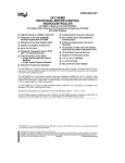
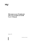
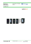
87C196JV 20 MHz
ADVANCED 16-BIT CHMOS MICROCONTROLLER
Automotive
Y
b 40§ C to a 125§ C Ambient
Y
High Performance CHMOS 16-Bit CPU
Y
Y
Y
Y
High Speed Peripheral Transaction
Server (PTS)
48 Kbytes of On-Chip EPROM
Y
Two 16-Bit Software Timers
Up to 1.5 Kbyte of On-Chip Register
RAM
Y
6 High Speed Capture/Compare (EPA)
Y
Full Duplex Synchronous Serial I/O
Port (SSIO)
Y
Two Flexible 16-Bit Timer/Counters
512 Bytes of Additional RAM
(Code RAM)
Y
Register-Register Architecture
Y
Flexible 8-/16-Bit External Bus
Y
6 Channel/10-Bit A/D with Sample/Hold
Y
1.4 ms 16 x 16 Multiply
Y
35 Prioritized Interrupt Sources
Y
2.4 ms 32/16 Divide
Y
Up to Seven 8-Bit (56) I/O Ports
Y
52-Pin PLCC Package
Y
Full Duplex Serial I/O Port
Y
Oscillator Fail Detect
Y
Dedicated Baud Rate Generator
The 87C196JV A-step (JV-A), is a new member of the MCSÉ 96 microcontroller family. This device is a
memory scalar of the 87C196JT A-step (JT-A) and is designed for strict functional and electrical compatibility.
The 87C196JV has the highest 52-lead memory density of the MCS 96 microcontroller family, with 48K of onchip EPROM, 1.5K of on-chip register RAM, and 512 bytes of additional RAM (Code RAM). The high memory
integration of the 87C196JV supports high-functionality in a low pin-count package and the use of the high
level programming language C.
The MCS 96 microcontroller family members are all high-performance microcontrollers with a 16-bit CPU. The
87C196JV is composed of the high-speed (20 MHz) core as well as the following peripherals: 48 Kbytes of
Program EPROM, up to 1.5 Kbyte of Register RAM. 512 bytes of code RAM (16-bit addressing modes) with
the ability to execute from this RAM space, a 6 channel-10-Bit/ g 3 LSB analog to digital converter with
programmable S/H times with conversion times k 5 ms at 16 MHz, an asynchronous/synchronous serial I/O
port (8096 compatible) with a dedicated 16-bit baud rate generator, an additional synchronous serial I/O port
with full duplex master/slave transceivers, a flexible timer/counter structure with prescaler, cascading, and
quadrature capabilities, 6 modularized multiplexed high speed I/O for capture and compare (called Event
Processor Array) with 250 ns resolution and double buffered inputs, a sophisticated prioritized interrupt structure with programmable Peripheral Transaction Server (PTS). The PTS has several channel modes, including
single/burst block transfers from any memory location to any memory location, a PWM and PWM toggle mode
to be used in conjunction with the EPA, and an A/D scan mode.
Additional SFR space is allocated for the EPA and can be ‘‘windowed’’ into the lower Register RAM area.
NOTICE: This is a production data sheet. The specifications are subject to change without notice.
*Other brands and names are the property of their respective owners.
Information in this document is provided in connection with Intel products. Intel assumes no liability whatsoever, including infringement of any patent or
copyright, for sale and use of Intel products except as provided in Intel’s Terms and Conditions of Sale for such products. Intel retains the right to make
changes to these specifications at any time, without notice. Microcomputer Products may have minor variations to this specification known as errata.
COPYRIGHT © INTEL CORPORATION, 1996
February 1996
Order Number: 272580-003
87C196JV
ARCHITECTURE
The 87C196JV A-step (JV-A), is the newest member
of the MCS 96 microcontroller family. This device is
a memory scalar of the 87C196JT A-step (JT-A) and
is designed for strict functional and electrical compatibility. The 87C196JV has the highest 52-lead
memory density of the MCS 96 microcontroller family, with 48K of on-chip EPROM, 1.5K of on-chip register RAM, and 512 bytes of additional RAM (Code
RAM). The high memory integration of the
87C196JV supports high-functionality in a low pincount package and the use of the high level programming language C.
CPU FEATURES
# Powerdown and Idle Modes
# 20 MHz Operating Frequency
# A High Performance Peripheral Transaction Server (PTS)
# 35 Interrupt Vectors
# 512 Bytes of Additional Code RAM
# 1.5 Kbyte of Additional Register RAM
# ‘‘Windowing’’ Allows 8-Bit Addressing to Some
16-Bit Addresses
# 1.4 ms 16 x 16 Multiply
# 2.4 ms 32/16 Divide
# Oscillator Fail Detect
PERIPHERAL FEATURES
#
#
#
#
Programmable A/D Conversion and S/H Times
6 Capture/Compare I/O with 2 Flexible Timers
4 Additional Software Timers
Synchronous Serial I/O Port for Full Duplex Serial I/O
# Total Utilization of ALL Available Pins (I/O Mux’d
with Control)
# 2 16-Bit Timers with Prescale and Cascading
# Up to 12 Externally Triggered Interrupts
272580 – 1
Figure 1. Block Diagram
2
87C196JV
272580 – 2
Figure 2. The 8XC196JV Family Nomenclature
272580 – 3
Figure 3. Package Diagram
3
87C196JV
PIN DESCRIPTIONS
Symbol
4
Name and Function
VCC
Main supply voltage ( a 5V).
VSS, VSS, VSS
Digital circuit ground (0V). There are three VSS pins, all of which MUST be
connected to a single ground plane.
VREF
Reference for the A/D converter ( a 5V). VREF is also the supply voltage to the
analog portion of the A/D converter and the logic used to read Port 0. Must be
connected for A/D and Port 0 to function.
VPP
Programming voltage for the EPROM parts. It should be a 12.5V for
programming. It is also the timing pin for the return from powerdown circuit.
Connect this pin with a 1 mF capacitor to VSS and a 1 MX resistor to VCC. If this
function is not used, VPP may be tied to VCC.
ANGND
Reference ground for the A/D converter. Must be held at nominally the same
potential as VSS.
XTAL1
Input of the oscillator inverter and the internal clock generator.
XTAL2
Output of the oscillator inverter.
P2.7/CLKOUT
Output of the internal clock generator. The frequency is (/2 the oscillator
frequency. It has a 50% duty cycle. Also LSIO pin.
RESET
Reset input to the chip. Input low for at least 16 state times will reset the chip. The
subsequent low to high transition resynchronizes CLKOUT and commences a 10state time sequence in which the PSW is cleared, bytes are read from 2018H and
201AH loading the CCBs, and a jump to location 2080H is executed. Input high for
normal operation. RESET has an internal pullup.
EA
Input for memory select (External Access). EA equal to a high causes memory
accesses to locations 2000H through 5FFFH to be directed to on-chip EPROM/
ROM. EA equal to a low causes accesses to these locations to be directed to offchip memory. EA e a 12.5V causes execution to begin in the Programming
Mode. EA latched at reset.
P5.0/ALE/ADV
Address Latch Enable or Address Valid output, as selected by CCR. Both pin
options provide a latch to demultiplex the address from the address/data bus.
When the pin is ADV, it goes inactive (high) at the end of the bus cycle. ADV can
be used as a chip select for external memory. ALE/ADV is active only during
external memory accesses. Also LSIO when not used as ALE.
87C196JV
PIN DESCRIPTIONS (Continued)
Symbol
Name and Function
P5.3/RD
Read signal output to external memory. RD is active only during external memory
reads or LSIO when not used as RD.
P5.2/WR/WRL
Write and Write Low output to external memory, as selected by the CCR, WR will
go low for every external write, while WRL will go low only for external writes
where an even byte is being written. WR/WRL is active during external memory
writes. Also an LSIO pin when not used as WR/WRL.
P1.0/T2CLK
Dual function I/O pin. Primary function is that of a bidirectional I/O pin, however it
may also be used as a TIMER2 Clock input. The TIMER2 will increment or
decrement on both positive and negative edges of this pin.
P1.2/T2DIR
Dual function I/Opin. Primary function is that of a bidirectional I/O pin, however it
may also be used as a TIMER2 Direction input. The TIMER2 will increment when
this pin is high and decrements when this pin is low.
PORT1/EPA0–3
P6.0–6.1/EPA8–9
Dual function I/O port pins. Primary function is that of bidirectional I/O. System
function is that of High Speed capture and compare. EPA0 and EPA2 have yet
another function of T2CLK and T2DIR of the TIMER2 timer/counter.
PORT 0/ACH2–7
6-bit high impedance input-only port. These pins can be used as digital inputs
and/or as analog inputs to the on-chip A/D converter. These pins are also used
as inputs to EPROM parts to select the Programming Mode.
P6.4–6.7/SSIO
Dual function I/O ports that have a system function as Synchronous Serial I/O.
Two pins are clocks and two pins are data, providing full duplex capability.
PORT 2
8-bit multi-functional port. All of its pins are shared with other functions.
PORT 3 and 4
8-bit bidirectional I/O ports with open drain outputs. These pins are shared with
the multiplexed address/data bus which has strong internal pullups.
5
87C196JV
ELECTRICAL CHARACTERISTICS
NOTICE: This is a production data sheet. The specifications are subject to change without notice.
ABSOLUTE MAXIMUM RATINGS**
*WARNING: Stressing the device beyond the ‘‘Absolute
Maximum Ratings’’ may cause permanent damage.
These are stress ratings only. Operation beyond the
‘‘Operating Conditions’’ is not recommended and extended exposure beyond the ‘‘Operating Conditions’’
may affect device reliability.
Storage Temperature ÀÀÀÀÀÀÀÀÀÀ b 60§ C to a 150§ C
Voltage from VPP or EA to
VSS or ANGND ÀÀÀÀÀÀÀÀÀÀÀÀÀÀ b 0.5V to a 13.0V
Voltage from Any Other Pin
to VSS or ANGND ÀÀÀÀÀÀÀÀÀÀÀÀÀ b 0.5V to a 7.0V
This includes VPP on ROM and CPU devices.
Power DissipationÀÀÀÀÀÀÀÀÀÀÀÀÀÀÀÀÀÀÀÀÀÀÀÀÀÀ0.5W
OPERATING CONDITIONS
Parameter
Min
Max
Units
TA
Symbol
Ambient Temperature under Bias
b 40
a 125
§C
VCC
Digital Supply Voltage
4.50
5.50
V
VREF
Analog Supply Voltage
4.50
5.50
V
FOSC
Oscillator Frequency
4
20
MHz(4)
NOTE:
ANGND and VSS should be nominally at the same potential.
DC CHARACTERISTICS
Symbol
(Under Listed Operating Conditions)
Parameter
Min
Typ
Max
Units
Test Conditions
95
mA
XTAL1 e 20 MHz,
VCC e VPP e VREF e 5.5V
(While Device in Reset)
ICC
VCC Supply Current
( b 40§ C to a 125§ C Ambient)
ICC1
Active Mode Supply
Current (Typical)
IREF
A/D Reference Supply
Current
2
5
mA
IIDLE
Idle Mode Current
15
40
mA
IPD
Powerdown Mode
Current
50
TBD
mA
VIL
Input Low Voltage
(All Pins)
b 0.5V
0.3 VCC
V
VIH
Input High Voltage (All Pins)
0.7 VCC
VCC a 0.5
V
6
60
mA
XTAL1 e 20 MHz,
VCC e VPP e VREF e 5.5V
VCC e VPP e VREF e 5.5V
(Note 6)
(Note 7)
87C196JV
DC CHARACTERISTICS
Symbol
(Under Listed Operating Conditions) (Continued)
Parameter
Min
Typ
Max
Units
Test Conditions
0.3
0.45
1.5
V
V
V
IOL e 200 mA(3, 5)
IOL e 3.2 mA
IOL e 7.0 mA
V
V
V
IOH e b 200 mA(3, 5)
IOH e b 3.2 mA
IOH e b 7.0 mA
VOL
Output Low Voltage
(Outputs Configured
as Push/Pull)
VOH
Output High Voltage
(Outputs Configured
as Push/Pull)
ILI
Input Leakage Current
(Std. Inputs, P3/4)
g 10
mA
VSS s VIN s VCC(2)
ILI1
Input Leakage Current
(Port 0ÐA/D Inputs)
g2
mA
VSS s VIN s VREF
IIH
Input High Current (NMI Pin)
a 175
mA
VSS s VIN s VCC
VOH2
Output High Voltage in RESET
VCC b 1V
V
IOH e b 15 mA(1)
IOH2
Output High Current in RESET
b 30
b 75
b 90
b 120
b 240
b 280
mA
mA
mA
RRST
Reset Pullup Resistor
6K
65K
X
VOL3
Output Low Voltage in RESET
(RESET pin only)
0.3
0.5
0.8
V
V
V
IOL3 e 4 mA (Note 8)
IOL3 e 6 mA
IOL3 e 8 mA
CS
Pin Capacitance
(Any Pin to VSS)
10
pF
FTEST e 1.0 MHz
RWPU
Weak Pullup Resistance (Approx)
X
(Note 6)
VCC b 0.3
VCC b 0.7
VCC b 1.5
150K
VOH2 e VCC b 1.0V
VOH2 e VCC b 2.5V
VOH2 e VCC b 4.0V
NOTES:
1. All BD (bidirectional) pins except CLKOUT. CLKOUT is excluded due to not being weakly pulled high in reset. BD pins
include Port1, Port2, Ports 3, 4 and 5 and Port6.
2. Standard Input pins include XTAL1, EA, RESET and Port 1/2/3/4/5/6 when configured as inputs.
3. All Bidirectional I/O pins when configured as Outputs (Push/Pull).
4. Device is Static and should operate below 1 Hz, but only tested down to 4 MHz.
5. Maximum IOL/IOH currents per pin will be characterized and published at a later date. Target values are g 10 mA.
6. Typicals are based on limited number of samples and are not guaranteed. The values listed are at room temperature and
VREF e VCC e 5.0V.
7. VIH Max for Port 0 pins e VREF a 0.5V.
8. This specification is not tested in production and is based upon theoretical estimates and/or product characterization.
7
87C196JV
AC CHARACTERISTICS
(Over Specified Operating Conditions)
Test Conditions: Capacitance Load on All Pins e 100 pF, Rise and Fall Times e 10 ns, FOSC e 20 MHz.
The system must meet these specifications to work with the 87C196JV
Symbol
Parameter
TAVDV
Address Valid to Input Data Valid
TRLDV
RD Active to Input Data Valid
TCLDV
CLKOUT Low to Input Data Valid
TRHDZ
End of RD to Input Data Float
TRXDX
Data Hold after RD Inactive
Min
Max
Units
3 TOSC b 55
TOSC b 25
ns
TOSC b 50
ns
TOSC
0
ns
ns
ns
AC CHARACTERISTICS
(Over Specified Operating Conditions)
Test Conditions: Capacitance Load on All Pins e 100 pF, Rise and Fall Times e 10 ns, FOSC e 20 MHz.
The 87C196JV will meet these specifications.
Symbol
8
Parameter
Min
Max
Units
FXTAL
Oscillator Frequency
4.0
20.0
MHz(1)
TOSC
Oscillator Period (1/Fxtal)
50
250
ns
TXHCH
XTAL1 High to CLKOUT
High or Low
20
110
ns(2)
TCLCL
CLKOUT Period
TCHCL
CLKOUT High Period
TCLLH
CLKOUT Falling Edge
to ALE Rising
TLLCH
ALE/ADV Falling Edge
to CLKOUT Rising
TLHLH
ALE/ADV Cycle Time
2 TOSC
ns
TOSC b 10
b 10
TOSC a 15
ns
15
ns
b 20
15
ns
4 TOSC
TOSC b 10
TOSC b 15
ns
TOSC a 10
TLHLL
ALE/ADV High Period
TAVLL
Address Setup to ALE/ADV
Falling Edge
ns
TLLAX
Address Hold after ALE/ADV
Falling Edge
TOSC b 40
ns
TLLRL
ALE/ADV Falling Edge to
RD Falling Edge
TOSC b 30
ns
ns
87C196JV
AC CHARACTERISTICS
(Over Specified Operating Conditions) (Continued)
Test Conditions: Capacitance Load on All Pins e 100 pF, Rise and Fall Times e 10 ns, FOSC e 20 MHz.
The 87C196JV will meet these specifications.
Symbol
Parameter
TRLCL
RD Low to CLKOUT
Falling Edge
TRLRH
RD Low Period
TRHLH
RD Rising Edge to
ALE/ADV Rising Edge
TRLAZ
RD Low to Address Float
Min
Max
Units
4
30
ns
TOSC a 25
ns(3)
5
ns(5)
TOSC b 5
TOSC
ns
TLLWL
ALE/ADV Falling Edge
to WR Falling Edge
TCLWL
CLKOUT Low to
WR Falling Edge
TQVWH
Data Stable to WR Rising Edge
TCHWH
CLKOUT High to WR
Rising Edge
TWLWH
WR Low Period
TOSC b 20
TWHQX
Data Hold after WR Rising Edge
TOSC b 25
TWHLH
WR Rising Edge to ALE/ADV
Rising Edge
TOSC b 10
TWHAX
AD8–15 Hold after WR Rising Edge
TOSC b 30(4)
ns
AD8–15 Hold after RD Rising Edge
TOSC b 30(4)
ns
TRHAX
TOSC b 10
b5
ns
25
ns
15
ns
TOSC b 23
b 10
ns
ns
ns
TOSC a 15
ns(3)
NOTES:
1. Testing performed at 4.0 MHz, however, the device is static by design and will typically operate below 1 Hz.
2. Typical specifications, not guaranteed.
3. Assuming back-to-back bus cycles.
4. 8-bit bus only.
5. TRLAZ (max) e 5 ns by design.
9
87C196JV
System Bus Timing
272580 – 4
10
87C196JV
EXTERNAL CLOCK DRIVE
Symbol
Parameter
Min
Max
Units
1/TXLXL
Oscillator Frequency
4.0
20
MHz
TXLXL
Oscillator Period (TOSC)
50
250
ns
TXHXX
High Time
0.35 TOSC
0.65 TOSC
ns
TXLXX
Low Time
0.35 TOSC
0.65 TOSC
ns
TXLXH
Rise Time
10
ns
TXHXL
Fall Time
10
ns
EXTERNAL CLOCK DRIVE WAVEFORMS
272580 – 5
AC TESTING INPUT, OUTPUT WAVEFORMS
FLOAT WAVEFORMS
272580 – 7
272580 – 6
NOTE:
AC Testing Inputs are driven at 3.5V for a logic ‘‘1’’ and
0.45V for a logic ‘‘0’’. Timing measurements are made
at 2.0V for a logic ‘‘1’’ and 0.8V for logic ‘‘0’’.
NOTE:
For timing purposes a port pin is no longer floating
when a 150 mV change from load voltage occurs and
begins to float when a 150 mV change from the loading
VOH/VOL level occurs IOL/IOH s 15 mA.
THERMAL CHARACTERISTICS
Device and Package
AN87C196JV
(52-Lead PLCC)
iJA
iJC
42§ C/W
15§ C/W
NOTES:
1. iJA e Thermal resistance between junction and the surrounding environment (ambient). Measurements
are taken 1 ft. away from case in air flow environment.
iJC e Thermal resistance between junction and package surface (case).
2. All values of iJA and iJC may fluctuate depending on
the environment (with or without airflow, and how much airflow) and device power dissipation at temperature of operation. Typical variations are g 2§ C/W.
3. Values listed are at a maximum power dissipation of
0.50W.
11
87C196JV
EXPLANATION OF AC SYMBOLS
Each symbol is two pairs of letters prefixed by ‘‘t’’ for time. The characters in a pair indicate a signal and its
condition, respectively. Symbols represent the time between the two signal/condition points.
Conditions:
Signals:
HÐ High
AÐ Address
LÐ Low
VÐ Valid
BÐ BHE
XÐ No Longer Valid
DÐ DATA
GÐ Buswidth
HAÐ HLDA
LÐ ALE/ADV
RÐ RD
CÐ CLKOUT
ZÐ Floating
WÐ WR/WRH/WRI
XÐ XTAL1
YÐ READY
EPROM SPECIFICATIONS
AC EPROM PROGRAMMING CHARACTERISTICS
Operating Conditions: Load Capacitance e 150 pF; TC e 25§ C g 5§ C, VREF e 5.0V g 0.5V, VSS,
ANGND e 0V. VPP e 12.5V g 0.25V; EA e 12.5V g 0.25V; FOSC e 5.0 MHz
Symbol
Parameter
Min
Max
Units
TAVLL
Address Setup Time
0
TOSC
TLLAX
Address Hold Time
100
TOSC
TDVPL
Data Setup Time
0
TOSC
TPLDX
Data Hold Time
400
TOSC
TLLLH
PALE Pulse Width
50
TOSC
TPLPH
PROG Pulse Width(3)
50
TOSC
TLHPL
PALE High to PROG Low
220
TOSC
TPHLL
PROG High to Next PALE Low
220
TPHDX
Word Dump Hold Time
TPHPL
PROG High to Next PROG Low
220
TOSC
TLHPL
PALE High to PROG Low
220
TOSC
TPLDV
PROG Low to Word Dump Valid
TSHLL
RESET High to First PALE Low
TPHIL
PROG High to AINC Low
TILIH
TILVH
TOSC
50
50
TOSC
TOSC
1100
TOSC
0
TOSC
AINC Pulse Width
240
TOSC
PVER Hold after AINC Low
50
TOSC
TILPL
AINC Low to PROG Low
170
TPHVL
PROG High to PVER Valid
TOSC
220
TOSC
NOTES:
1. Run time programming is done with FOSC e 6.0 MHz to 10.0 MHz, VCC, VPD, VREF e 5V g 0.5V, TC e 25§ C g 5§ C and
VPP e 12.5V g 0.25V. For run-time programming over a full operating range, contact factory.
2. Programming Specifications are not tested, but guaranteed by design.
3. This specification is for the word dump mode. For programming pulses use 300 TOSC a 100 ms.
DC EPROM PROGRAMMING CHARACTERISTICS
Symbol
IPP
Parameter
VPP Programming Supply Current
Min
Max
Units
100
mA
NOTE:
VPP must be within 1V of VCC while VCC k 4.5V. VPP must not have a low impedance path to ground or VSS while VCC l
4.5V.
12
87C196JV
EPROM PROGRAMMING WAVEFORMS
SLAVE PROGRAMMING MODE DATA PROGRAM MODE WITH SINGLE PROGRAM PULSE
272580 – 8
SLAVE PROGRAMMING MODE IN WORD DUMP OR DATA VERIFY MODE WITH AUTO INCREMENT
272580 – 9
SLAVE PROGRAMMING MODE TIMING IN DATA PROGRAM MODE WITH REPEATED PROG PULSE
AND AUTO INCREMENT
272580 – 10
13
87C196JV
A TO D CONVERTER SPECIFICATIONS
both the resistor ladder and the digital portion of the
converter and input port pins.
The speed of the A/D converter in the 10-bit or 8-bit
modes can be adjusted by setting the ADÐTIME
special function register to the appropriate value.
The ADÐTIME register only programs the speed at
which the conversions are performed, not the speed
at which it can convert correctly.
For testing purposes, after a conversion is started,
the device is placed in the IDLE mode until the conversion is complete. Testing is performed at VREF e
5.12V and 20 MHz operating frequency.
The converter is ratiometric, so absolute accuracy is
dependent on the accuracy and stability of VREF.
VREF must be within 0.5V of VCC since it supplies
There is an ADÐTEST register that allows for conversion on ANGND and VREF as well as zero offset
adjustment. The absolute error listed is without doing any adjustments.
A/D OPERATING CONDITIONS(1)
Description
Min
Max
Units
TA
Symbol
Automotive Ambient Temperature
b 40
a 125
§C
VCC
Digital Supply Voltage
4.50
5.50
V
VREF
Analog Supply Voltage
4.50
5.50(2, 3)
TSAM
Sample Time
2.0
TCONV
Conversion Time
15
18
ms(4)
FOSC
Oscillator Frequency
4
20
MHz
V
ms(4)
NOTES:
1. ANGND and VSS should nominally be at the same potential.
2. VREF must not exceed VCC by more than a 0.5V.
3. Testing is performed at VREF e 5.12V.
4. The value of ADÐTIME must be selected to meet these specifications.
Parameter
Typical*(1)
Resolution
Absolute Error
Full Scale Error
g2
Zero Offset Error
g2
Min
Max
Units**
1024
10
1024
10
Level
Bits
0
b3
a3
LSBs
LSBs
LSBs
Non-Linearity
Differential Non-Linearity
Channel-to-Channel Matching
Repeatability
g 0.25
Temperature Coefficients:
Offset
Fullscale
Differential Non-Linearity
0.009
0.009
0.009
Off Isolation
g3
LSBs
l b 0.5
a 0.5
LSBs
0
g1
LSBs
LSBs(1)
0
LSB/C(1)
LSB/C(1)
LSB/C(1)
dB(1, 2, 3)
b 60
Feedthrough
b 60
dB(1, 2)
VCC Power Supply Rejection
b 60
dB(1, 2)
Input Resistance
750
1.2K
X(1)
DC Input Leakage
0
2
mA
NOTES:
*These values are expected for most parts at 25§ C but are not tested or guaranteed.
**An ‘‘LSB’’, as used here, has a value of approximately 5 mV. (See Automotive Handbook for A/D glossary of terms).
1. These values are not tested in production and are based on theoretical estimates and/or laboratory test.
2. DC to 100 KHz
3. Multiplexer Break-Before-Make Guaranteed.
14
87C196JV
AC CHARACTERISTICSÐSERIAL PORTÐSHIFT REGISTER MODE
SERIAL PORT TIMINGÐSHIFT REGISTER MODE
Test Conditions: TA e b 40§ C to a 125§ C; VCC e 5.0V g 10%; VSS e 0.0V; Load Capacitance e 100 pF
Symbol
Parameter
Min
TXLXL
Serial Port Clock Period
8 TOSC
TXLXH
Serial Port Clock Falling
Edge to Rising Edge
4 TOSC b 50
TQVXH
Output Data Setup
to Clock Rising Edge
TXHQX
Output Data Hold
after Clock Rising Edge
TXHQV
Next Output Data Valid
after Clock Rising Edge
TDVXH
Input Data Setup
to Clock Rising Edge
TXHDX(8)
Input Data Hold
after Clock Rising Edge
TXHQZ(8)
Last Clock Rising to
Output Float
Max
Units
4 TOSC a 50
ns
ns
3 TOSC
ns
2 TOSC b 50
ns
2 TOSC a 50
ns
2 TOSC a 200
ns
0
ns
5 TOSC
ns
NOTES:
8. Parameter not tested.
WAVEFORMÐSERIAL PORTÐSHIFT REGISTER MODE 0
SERIAL PORT WAVEFORMÐSHIFT REGISTER MODE
272580 – 11
15
87C196JV
52-LEAD DEVICE DESIGN CONSIDERATIONS
The 87C196JV A-step is a memory scalar of the 52lead 87C196JT A-step designed for strict functional
and electrical compatibility. Both the 87C196JV and
87C196JT are 52-lead members of the Kx product
family. Some functions that are on 68-lead devices
are not supported on 52-lead devices because of
the reduced pin-count. Following are the functionality differences between 52-lead Kx family members
and 68-lead Kx family members.
68-Lead Functions Unsupported on the 52-Lead
87C196JV:
Analog Channels 0 and 1
INST Pin Functionality
SLPINT and SLPCS Pin Support
HLD/HLDA Functionality
External Clocking/Direction of Timer1
WRH or BHE Functions
Dynamic Buswidth
Dynamic Wait State Control
The following is a list of recommended practices
when using 52-lead Kx devices:
(1) External Memory. Use an 8-bit bus mode only.
There is neither a WRH or BUSWIDTH pin. The
bus cannot dynamically switch from 8- to 16-bit
or vice versa. Set the CCB bytes to an 8-bit only
mode, using WR function only.
(2) Wait State Control. Use the CCB bytes to configure the maximum number of wait states. If the
READY pin is selected to be a system function,
the device will lockup waiting for READY. If the
READY pin is configured as LSIO (default after
RESET), the internal logic will receive a logic
‘‘0’’ level and insert the CCB defined number of
wait states in the bus cycle. DON’T USE IRC e
‘‘111’’.
(3) NMI Support. The NMI is not bonded out. Make
the NMI vector at location 203Eh vector to a
Return instruction. This is for glitch safety protection only.
(4) Auto-Programming Mode. The 52-lead device
will ONLY support the 16-bit zero wait state bus
during auto-programming.
(5) EPA4 through EPA7. Since the JT/JR/JQ devices use the KR silicon, these functions are in
the device, just not bonded out. A programmer
can use these as compare only channels or for
other functions like software timer, start and
A/D conversion, or reset timers.
(6) Slave Port Support. The Slave port can not be
used on 52-lead devices due to P5.4/SLPINT
and P5.1/SLPCS not being bonded-out.
(7) Port Functions. Some port pins have been removed. P5.7, P5.6, P5.5, P5.1, P6.2, P6.3, P1.4
through P1.7, P2.3, P2.5, P0.0 and P0.1. The
PxREG, PxSSEL, and PxIO registers can still be
updated and read. The programmer should not
use the corresponding bits associated with the
removed port pins to conditionally branch in
software. Treat these bits as RESERVED.
Additionally, these port pins should be setup internally by software as follows:
1. Written to PxREG as ‘‘1’’ or ‘‘0’’.
2. Configured as Push/Pull, PxIO as ‘‘0’’.
3. Configured as LSIO.
This configuration will effectively strap the pin
either high or low. DO NOT Configure as
Open Drain output ‘’1’’, or as an Input pin.
This device is CMOS.
(8) EPA Timer RESET/Write Conflict. If the user
writes to the EPA timer at the same time that the
timer is reset, it is indeterminate which will take
precedence. Users should not write to a timer if
using EPA signals to reset it.
(9) Valid Time Matches. The timer must increment/decrement to the compare value for a
match to occur. A match does not occur if the
timer is loaded with a value equal to an EPA
compare value. Matches also do not occur if a
timer is reset and 0 is the EPA compare value.
(10) P6ÐPIN.4 – .7 Not Updated Immediately. Values written to P6ÐREG are temporarily held in
a buffer. If P6ÐMODE is cleared, the buffer is
loaded into P6ÐREG.x. If P6ÐMODE is set,
the value stays in the buffer and is loaded into
P6ÐREG.x when P6ÐMODE.x is cleared.
Since reading P6ÐREG returns the current value in P6ÐREG and not the buffer, changes to
P6ÐREG cannot be read until/unless
P6ÐMODE.x is cleared.
(11) Write Cycle during Reset. If RESET occurs
during a write cycle, the contents of the external
memory device may be corrupted.
(12) Indirect Shift Instruction. The upper 3 bits of
the byte register holding the shift count are not
masked completely. If the shift count register
has the value 32 c n, where n e 1, 3, 5, or 7,
the operand will be shifted 32 times. This
should have resulted in no shift taking place.
(13) P2.7 (CLKOUT). P2.7 (CLKOUT) does not operate in open drain mode. On the 87C196JV
CLKOUT is active during RESET.
87C196JV ERRATA
No known errata at this time.
16
87C196JV
87C196JR/JQ D-STEP TO 87C196JV
A-STEP DESIGN CONSIDERATIONS
Following is a list of differences between the JR-C
and the JV-A, JT-A:
1. Memory Scalar
1. Port 3 Push-Pull Operation
The 87C196JV A-step is a memory scalar of the
87C196JR D-step.
It was discovered on JR-C that if Port 3 is selected
for push-pull operation (P34ÐDRV register) during
low speed I/O (LSIO), the port was driving data
when the system bus was attempting to input data. It
is rather unlikely that this errata would affect an application because the application would have to use
Port 3 for both LSIO and as an external addr/data
bus. None the less, this errata was corrected on the
JT-A and JV-A.
87C196JR
D-Step
Register RAM
87C196JV
A-Step
18h to 1FFh
18h to 3FFh
and
1C00h to 1DFFh
Internal (Code) RAM
400h to 4FFh
400h to 5FFh
Internal ROM/EPROM 2000h to 5FFFh 2000h to DFFFh
2. VOH2 Strengthened
2. 1B00–1BDFh External Addressing
The 87C196JR/JQ D-step cannot access external
memory locations 1B00h–1BDFh. This JR/JQ
D-step errata has been corrected on the 87C196JV
A-step. A bus cycle does not occur when these addresses are accessed. If attempting to read from
1B00h–1BDFh a value of FFh is returned even
though a read cycle is not generated. Writing to
these locations will not generate an external bus cycle either.
87C196JR/JQ C-STEP TO JV A-STEP
DESIGN CONSIDERATIONS
This section documents differences between the
87C196JR C-step (JR-C) and the 87C196JV A-step
(JV-A). For a list of design considerations between
68-lead and 52-lead devices, please refer to the 52lead Device Design Considerations section of this
data sheet. Since the 87C196JQ is simply a memory
scalar of the 87C196JR, the term ‘‘JR’’ in this section will refer to both the JR and JQ versions of the
device unless otherwise noted.
The JR-C is simply a 87C196KR C-step (KR-C) device packaged within a 52-lead package. This reduction in pin count necessitated not bonding-out certain pins of the KR-C device. The fact that these
‘‘removed pins’’ were still present on the device but
not available to the outside world allowed the programmer to take advantage of some of the 68-lead
KR features.
The JV-A is a fully-optimized 52-lead device based
on the 87C196JT A-step device which is based on
the JR-D step device. The JT-A design database
was used to assure that the JV-A would be fully
compatible with the KR-C, JR-C, JR-D and other Kx
family members. The main difference in the JV-A
and JT-A as compared to the JR-C is that several of
the unused (not bonded-out) functions on the JR-C
were removed altogether on the JT-A.
The DC Characteristics section of the Automotive
KR Data Sheet contains a parameter, VOH2 (Output
High Voltage in RESET (BD ports)) which is specified at VCC b 1V min at IOH2 e b 15 mA. This specification indicates the strength of the internal weak
pull-ups that are active during and after reset. These
weak pull-ups stay active until the user writes to
PxMODE (previously known as PxSSEL) and configures the port pin as desired.
These pull-ups do not meet this VOH2 spec on the
JR-C. The weak pull-ups on specified JT-A and JV-A
ports have been enhanced to meet the published
specification of IOH2 e b 15 mA.
3. ONCE Mode
ONCE mode is entered by holding a single pin low
on the rising edge of RESET. On the KR, this pin is
P5.4/SLPINT. The JR-C does not support ONCE
mode since P5.4/SLPINT (ONCE mode entry pin) is
not bonded-out on these devices. To provide ONCE
mode on the JT-A and JV-A, the ONCE mode entry
function was moved from P5.4/SLPINT to P2.6/
HLDA. This will allow the JT-A and JV-A to enter
ONCE mode using P2.6 instead of removed pin
P5.4.
4. PORT0
On the JR-C, P0.0 and P0.1 are not bonded out.
However, these inputs are present in the device and
reading them will provide an indeterminate result.
On the JT A-step and JV-A the analog inputs for
these two channels at the multiplexer are tied to
VREF. Therefore, initiating an analog conversion on
ACH0 or ACH1 will result in a value equal to full
scale (3FFh). On the JT A-step and JV-A the digital
inputs for these two channels are tied to ground,
therefore reading P0.0 or P0.1 will result in a digital
‘‘0’’.
17
87C196JV
5. PORT1
7. PORT5
On the JR-C, P1.4, P1.5, P1.6 and P1.7 are not
bonded out but are present internally on the device.
This allows the programmer to write to the port registers and clear, set or read the pin even though it is
not available to the outside world. However, to maintain compatibility with JT A-step, JV A-step and future devices, it is recommended that the corresponding bits associated with the removed pins
NOT be used to conditionally branch in software.
These bits should be treated as reserved.
On the JR-C, P5.1, P5.4, P5.5, P5.6 and P5.7 are not
bonded out but are present internally on the device.
On the JT A-step and JV A-step unused port logic
for these four port pins has been removed from the
device and is not available to the programmer. Corresponding bits in the port registers have been
‘‘hard-wired’’ to provide the following results when
read:
Register Bits
P1ÐPIN.x
(x e 4,5,6,7)
P1ÐREG.x
(x e 4,5,6,7)
P1ÐDIR.x
(x e 4,5,6,7)
P1ÐMODE.x
(x e 4,5,6,7)
When Read
When Read
(x e 1,4,5,6,7)
1
1
P5ÐREG.x
(x e 1,4,5,6,7)
1
0
P5ÐDIR.x
(x e 1,4,5,6,7)
1
P5ÐMODE.x
(x e 1,4,6)
0
1
On the JR-C, P2.3 and P2.5 are not bonded out but
are present internally on the device. This allows the
programmer to write to the port registers and clear,
set or read the pin even though is not available to
the outside world. However, to maintain compatibility
with JT A-step, JV A-step and future devices, it is
recommended that the corresponding bits associated with the removed pins not be used to conditionally branch in software. These bits should be treated
as reserved.
On the JT-A and JV-A, unused port logic for these
two port pins has been removed from the device and
is not available to the programmer. Corresponding
bits in the port registers have been ‘‘hardwired’’ to
provide the fdllowing results when read:
18
Register Bits
P5ÐPIN.x
6. PORT2
When Read
P2ÐPIN.x
(x e 3,5)
1
P2ÐREG.x
(x e 3,5)
1
P2ÐDIR.x
(x e 3,5)
1
P2ÐMODE.x
(x e 3,5)
0
Writing to these bits will have no effect.
On the JT A-step and JV A-step unused port logic
for these five port pins has been removed from the
device and is not available to the programmer. Corresponding bits in the port registers have been
‘‘hardwired’’ to provide the following results when
read:
1
Writing to these bits will have no effect.
Register Bits
This allows the programmer to write to the port registers and clear, set or read the pin even though it is
not available to the outside world. However, to maintain compatibility with JT A-step, JV A-step and future devices, it is recommended that the corresponding bits associated with the removed pins not
be used to conditionally branch in software. These
bits should be treated as reserved.
P5ÐMODE.x (x e 5)
(EAÝ e 0)
(x e 5)
(EAÝ e 1)
P5ÐMODE.x
P5ÐMODE.x (x e 7)
1
0
1
Writing to these bits will have no effect.
8. PORT6
On the JR-C, P6.2 and P6.3 are not bonded out but
are present internally on the device. This allows the
programmer to write to the port registers and clear,
set or read the pin even though it is not available to
the outside world. However, to maintain compatibility
with JT A-step, JV A-step and future devices, it is
recommended that the corresponding bits associated with the removed pins not be used to conditionally branch in software. These bits should be treated
as reserved.
87C196JV
On the JT A-step and JV A-step, unused port logic
for these two port pins has been removed from the
device and is not available to the programmer. Corresponding bits in the port registers have been
‘‘hardwired’’ to provide the following results when
read:
Register Bits
When Read
P6ÐPIN.x
(x e 2,3)
1
P6ÐREG.x
(x e 2,3)
1
P6ÐDIR.x
(x e 2,3)
1
P6ÐMODE.x
(x e 2,3)
0
10. EPA Channels 4 through 7
The JR C-step device is simply a 68-lead KR-C device packaged in a 52-lead package. The reduced
pin-out is achieved by not bonding-out the unsupported pins. EPA4 – EPA7 are among these pins that
are not bonded-out. The fact that EPA4 – EPA7 are
still present allows the programmer to use these
channels as software timers, to start A/D conversions, reset timers, etc. All of the port pin logic is still
present and it is possible to use the EPA to toggle
these pins internally. Please refer to the 52-Lead Device section in this Data Sheet for further information.
Writing to these bits will have no effect.
9. 8XC196JQ Internal to External Memory Rollover Point
8XC196JQ devices are simply 8XC196JR devices
with less memory. Both the JQ-C and JQ-D are fabricated from the JR-C and JR-D respectfully. The difference between JQ and JR devices is that memory
locations beyond the supported boundaries on the
JQ are not tested in production and should not be
used. Any software which relies upon reading or writing these locations may not function correctly. Following are the supported memory maps for these
devices:
JQ C- and
D-Step
Register RAM
18h to 17Fh
Internal (Code) RAM 400h to 47Fh
Internal
ROM/EPROM
JR C- and
D-Step
On the JT A-step and JV A-step the EPA4 – EPA7
logic has NOT been removed from the device. This
allows the programmer to still use these channels
(as on the JR C-step) for software timers, etc. The
only difference is that the associated port pin logic
has been removed and does not exist internally. To
maintain JR C-step to JT A-step and JV A-step compatibility, programmers should make sure that their
software does not rely upon the removed port pin
logic.
11. EPA Overruns
EPA ‘‘lock-up’’ can occur if overruns are not handled
correctly, refer to Intel Techbit ÝDB0459 ‘‘Understanding EPA Capture Overruns’’, date 12-9-93. Applies to EPA channels with interrupts and overruns
enabled (ON/RT bit set to 1).
18h to 1FFh
400h to 4FFh
2000h to 4FFFh 2000h to 5FFFh
It is important to note that the internal to external
memory roll-over point for both the JR and JQ devices is the same (6000h and above goes external).
Two guidelines the programmer should follow to insure no problems are encountered when using JQ
devices are:
a) For JQ devices, the program must contain a
jump to a location greater than 5FFFh before the
12K boundary (4FFFh) is reached. This is necessary only if greater than 12K of program memory
is required with a JQ device and portions of the
program execute from internal ROM/EPROM.
b) For JQ devices with EAÝ tied to ground, use
only internal program memory from 2000h to
4FFFh. Do not use the unsupported locations
from 5000h to 5FFFh.
12. Indirect Addressing with Auto-Increment
For the special case of a pointer pointing to itself
using auto-increment, an incorrect access of the incremented pointer address will occur instead of an
access to the original pointer address. All other indirect auto-increment accesses will not be effected.
Please refer to Techbit ÝMCO593.
Incorrect sequence: Results in ax being incremented by 1 and the contents of the address pointed
to by ax a 1 to be loaded into
bx.
ld
ax,#ax
ldb bx,[ax]0
Suggested sequence: Results in the contents of the
address pointed to by ax to
be loaded into bx and ax incremented by 1.
ld ax,#bx; where ax does not equal bx
ldb cx,[ax] a
19
87C196JV
87C196JT TO 87C196JV DESIGN
CONSIDERATIONS
1. The additional register RAM on the 87C196JV is
mapped to 1C00h to 1DFFh. On the 87C196JT
this memory range is mapped as external memory.
2. The 87C196JV has 48K of EPROM located from
2080h to DFFFh. The JT has 32K of EPROM located from 2080h to 9FFFh. Memory accesses
between 1E00h and FFFFh go external for the
87C196JV. Access between A000h to FFFFh go
external for the 87C196JT.
1EFFh
Mapped as external memory on JV, JT,
and rest of Kx family
1E00h
1DFFh
1C00h
Additional Register RAM on JV.
1BFFh
External Memory Space on JV/JT and
rest of Kx family
0600h
05FFh
0400h
Code RAM. Same on JV, JT, KT
03FFh
0018h
Register RAM. Same on JV, JT, KT
0017h
Core Special Function Registers. Same
on JV, JT, and rest of Kx/Jx family
MEMORY MAP FOR JV
DFFFh
2080h
207Fh
2000h
1FFFh
1F00h
EPROM (Internal) 48 KByte.
User EPROM starts here. JV/JT and all
Kx products same.
Chip configuration bytes, PTS Vectors,
Interrupt Vectors, Security Key
JV/JT and all Kx products same. (See
Kx User’s manual Table 3.2)
Internal Special Function Registers
(SFR’s) (16-bit addressable) JV identical to JT and rest of Kx family. JV/JT
‘reserved’ locations (see Figure 3.2 Kx
User’s Manual).
0000h
DATASHEET REVISION HISTORY
This is the (-003) version of the 87C196JV datasheet.
1. The TRLDV specification was changed from
TOSC b 22 to TOSC b 25.
2. Design Consideration (13) changed to indicate
CLKOUT active during reset.
3. VOL3 estimate added.
INTEL CORPORATION, 2200 Mission College Blvd., Santa Clara, CA 95052; Tel. (408) 765-8080
INTEL CORPORATION (U.K.) Ltd., Swindon, United Kingdom; Tel. (0793) 696 000
INTEL JAPAN k.k., Ibaraki-ken; Tel. 029747-8511
Printed in U.S.A./xxxx/0296/B10M/xx xx