1
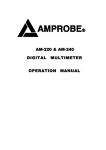
MASTECH® MS8239A Digital Multimeter User’s Manual Table of Contents Overview…………………………………………………1 Safety instructions………………………………………1 Safe working habits……………………………………1 Electric symbols…………………………………………4 Meter instructions………………………………………5 Meter appearance…………………………………5 Display……………………………………………6 Measuring operation……………………………………7 Data hold…………………………………………7 DC/AC voltage measurement………………..……7 DC current measurement……………………..……8 Resistance measurement……………………..……9 Continuity measurement…………………..……10 Diode test…………..……………………..……10 Battery test……………………..…………..……11 General specifications……….…………………………12 Accuracy indicators……………………………………13 DC voltage………………………………………13 AC voltage……………………..…………..……13 Resistance measurement…………………..……14 Diode…………..…………………………..……14 Continuity measurement……………..……..……14 DC current………………………………………15 Battery test……………………..…………..……15 Maintenance……….……………………………………16 General maintenance……………………..………16 Replace battery……………………………..……17 Replace fuse…………………….…………..……17 Overview Warning To avoid electric shock or personal injury, please read “safety information” and “warning and related notes” carefully before using the meter The MS8239A is a small hand-held, safe and reliable 3.5” digital multimeter with stable performance and novel structure. It can be used to measure DC voltage, DC current, resistance, diode forward voltage drop, circuit continuity and to test batteries. It is an ideal maintenance tool easily carried by a large number of users. Safety instructions The MS8239A digital multimeter has been designed according to International Electro Safety Standard IEC- 1010 (61010-1@IEC: 2001) concerning safety requirements for electronic measuring instruments and hand-held digital multimeters. It meets the requirements for CAT.Ⅲ 600V of IEC1010 and grade 2 for pollution. Users should use the meter strictly according to the provisions of this manual. Otherwise, the warranty for the meter may become invalid. The warnings in the user manual are used to remind users of possible dangers or dangerous actions. The notes in the user manual are to remind users of conditions or actions that may cause damage to the measured object. Safe working habits To avoid possible electric shock or personal injury as well as damage to the meter or measured objects, please use the meter according to the following procedures: 1 Check the case before using the meter. Don't use the meter with damaged case。 Check to see if the case is cracked or lacks plastic parts. Please pay special attention to the joint insulating layer. Check to see if the test wire has insulation damage or bare metal. Check test wire continuity. If the wire is damaged, please replace it with a new one before using the meter. Measure known voltage with the meter to verify that the meter is working properly. If the meter is working abnormally, stop using it immediately. A protective device may be damaged. If there is any doubt, please have the meter inspected by a qualified technician. Do not test voltage exceeding rated voltage marked on the meter. When testing voltage exceeding 30v AC voltage RMS, 42v AC peak or 60v DC, be particularly careful to avoid electric shock. When measuring, use correct jack, and select the proper function and measuring range. Do not use the meter in explosive gas, vapor or dusty environments. When using the probe, fingers should be behind the probe protection device. When connecting circuits, connect the common test line first, then connect the charged test line. When disconnecting circuits, disconnect the charged test line first, then disconnect the common test line. Before measuring resistance, continuity, and diodes, first turn off power and discharge all high voltage capacitors. 2 If the meter is not used in accordance with the instructions, the meter’s safety protective function may become invalid. For all DC measurements, to avoid the risk of electric shock, please use AC function to verify the existence of any AC voltage. Then, select DC voltage measuring range equal to or greater than the AC measuring range. Before measuring current, please check the meter fuse, shut off power to the circuit to be tested, then connect the meter and energize the circuit. When opening the case (or part of the case), turn the meter off. When the battery low voltage indicator “ ” becomes lit, replace the battery at once. A low battery will cause meter reading errors and may result in electric shock or personal injury. Before opening the case or the battery cover, remove the test wire from the meter. When maintaining the meter, use replacement parts specified by the factory. 3 Electric symbols Important safety information ~ AC (Alternating Current) DC (Direct Current) AC or DC Ground wire Double insulation protection Fuse Accord with the related EU laws and regulations 4 Meter instructions Meter appearance 1 2 3 4 5 6 ①.LCD display ②.Data hold key ③.Function selection rotary switch ④.Positive input jack of 10A (connected with the red test probe) ⑤.All the common input jacks for measuring (connected with the black test probe). ⑥.Positive input jack of voltage, resistance, mA current, diode, continuity and battery test (connected with the red test probe) 5 Display ①.Battery low voltage indicator ②.Data hold indicator ③.Numerical value display ④.Numerical value polarity indicator (negative sign) 6 Measuring operation Data hold The data hold function can keep the current readings on the display. To enter and exit reading maintenance mode: ①.Press the “HOLD” key, the reading will be stored and “H” symbol will display on the LCD display. ②.Press the “HOLD” key again to return the meter to the normal measurement state. AC/DC voltage measurement: ①.Rotate the function selection switch to appropriate AC or DC voltage measurement position. ②.Connect the black and red test probes to the COM input jack and VΩmA input jack, respectively.. ③.Measure the voltage of circuit to be tested with other ends of test probes (connected with the circuit to be tested in parallel). ④.Read the measured value from the LCD display. When measuring the DC voltage, the display will simultaneously show the voltage polarity which is connected with the red test probe. Warning Don’t measure any RMS voltage higher than 600V DC or AC, to prevent injury or damage to meter and equipment. 7 DC current measurement: ①.Turn off the power to the circuit to be tested. Discharge all the high voltage capacitors on the circuit to be tested. ②.Rotate the function selection switch to the appropriate DC current position. ③.Depending on the size of the current to be measured, connect the red test probe to 10A or mA input jack; connect the black test probe to COM input jack. ④.Turn off the circuit to be tested. Connect the black test probe to one end of the disconnected circuit (low voltage relatively), and the red test probe is connected to the other end of disconnected circuit (high voltage relatively). (Reversing test probes would make reading become negative, but the meter won’t be damaged.) ⑤.Connect the power supply to the circuit, then read the display reading. If the display shows only “1”, the input is out of the selected input range. In this case, rotate the switch to a higher measuring range. Warning To prevent injury or damage to meter and equipment, do not make current measurements if voltage exceeds 250V. Note Before measuring current, first check the meter's fuse. When measuring, use correct input end and function. When the test probe is inserted to the current input end, don’t connect the other end of the test probe with any circuit in parallel. 8 Resistance measurement: ①.Rotate the function selection switch to an appropriate resistance position, and turn off the power to the circuit to be tested ②.Connect the black and red test probe to COM input jack and VΩmA input jack, respectively. ③.Measure the resistance of the circuit with other ends of test probes. ④.Read the resistance value from the LCD display. Here are some tips for measuring resistance: The resistance measured on a circuit is usually different from the rated value of resistance. This is because the test current of the meter will flow through all the possible channels between the test probes. When measuring low resistance, to ensure the accuracy of the measurement, make a short circuit between the test probes and read the resistance value of the short circuit. This resistance value should be subtracted after measuring the resistance to be tested. When there is no input (for example, open circuit), the display will show “1”, which means that the measured value is out of range. Warning When measuring resistance or circuit continuity, to avoid injury or meter damage, turn off the power to the circuit and discharge all capacitors. 9 Continuity measurement: ①.Rotate the function selection switch to continuity measurement position, and turn off the power to the circuit to be tested ②.Connect the black and red test probe to COM input jack and VΩmA input jack, respectively. ③.Measure the circuit to be tested with other two ends of the test probes. ④.If the measured circuit resistance is less than about 50, the buzzer will sound continuously. Warning When measuring resistance or circuit continuity, to avoid injury or meter damage, turn off the power to the circuit and discharge all capacitors Diode Test: ①.Rotate the function selection switch to diode position, and turn off the power to the circuit to be tested ②.Connect the black and red test probe to COM input jack and VΩmA input jack, respectively. ③.Connect the black and red test probe to cathode and anode of the diode to be tested, respectively. The meter will display the diode’s forward bias voltage value. If the test probe polarity is reversed, the meter will display “1”, which distinguishes the diode’s cathode and anode. 10 Warning When measuring diodes, to avoid injury or meter damage, turn off the power to the circuit and discharge all capacitors. Battery test ①.Place the function measuring range switch to the battery testing position. ②.Insert the red probe to VΩmA input jack. Insert the black probe to COM input jack. ③.Connect free end of the red probe to positive and the free end of the black probe to negative end of the battery to be tested. ④.Read the result from the LCD display. Warning Don't input voltage higher than 60V DC or 30V AC, to prevent electric shock or meter damage. General specifications Operating environment and condition: CAT.Ⅲ, pollution grade: Ⅱ. Elevation < 2000 m 11 600V Environmental temperature and humidity: 0~40°C, <80% RH (do not use meter when temperature <10°C). Storage temperature and humidity: -10~60°C and <70% RH (remove the battery). Temperature coefficient: 0.1 Accuracy /°C(<18°C or >28°C). The maximum allowable voltage between measurement end and ground: 600V DC or 600V AC RMS. Fuse protection: grade mA: fuse F200mA/500V grade 10A: fuse F10A/500V Sampling rate: about 3 times/s. Display: 3.5” digital LCD display. Over-range indication: LCD will show “1”. Low battery indication: When the battery voltage is lower than the normal operating voltage, “ ” will display on the LCD display. Input polarity indication: automatically display “”. Power supply: AAA 1.5V batteries. Accuracy indicators Accuracy: ( of reading + digits) with one year of warranty. Reference conditions: environmental temperature is from 18°C~28°C, relative humidity is not more than 80 . 12 DC voltage Measuring Resolution Accuracy range 200mV 0.1mV 2V 0.001V ±(0.5% of reading +3 digits) 20V 0.01V 200V 0.1V 600V 1V ±(0.8% of reading +3 digits) Input impedance: 1M Maximum input voltage: 600V DC or AC RMS, 250V DC or AC RMS with the measuring range of 200mV. AC voltage Measuring Resolution Accuracy range 200V 0.1V ±(1.2% of reading +10 digits) 600V 1V Input impedance: 1M Maximum input voltage: 600V DC or AC RMS, 250V DC or AC RMS with the measuring range of 200mV. Frequency response: 40Hz~400Hz, sine wave RMS (average response) Resistance Measuring range 200 2k 20k 200k 2M Resolution Accuracy 0.1 0.001k 0.01k 0.1k 0.001M ±(0.8% of reading +5 digits) 13 Overload protection: 250V DC or AC (RMS) Diode Function Measuring range Test Environment Forward DC current: about 1mA; Reverse DC voltage: Diode Test 2V 0.001V about 2.5V. Display approximation of diode forward voltage drop. Overload protection: 250V DC or AC (RMS) Continuity measurement Function Description Test Environment When built-in buzzer Open circuit sounds, the resistance to voltage: about be tested is less than 2.5V about 60. Overload protection: 250V DC or AC (RMS) Direct Current Measuring Resolution Accuracy range 20mA 0.01mA ±(1.0% of reading +5 digits) 200mA 0.1mA ±(2.0% of reading +10 10A 10mA digits) Overload protection: grade mA: Fuse (F200mA/600V) Resolution protection; grade 10A: Fuse (F10A/500V) protection. 14 Maximum input current: grade mA: 200mA DC or AC RMS; grade 10A: 10A DC or AC RMS When measured current is greater than 2A, the continuous measurement time cannot be not more than 2 minutes. Disconnect the current and wait 10 minutes before making another measurement. Battery test Measuring Resolution Built-in load resistance range 12V 0.01V 300Ω 9V 0.01V 1.8kΩ 1.5V 0.001V 36Ω Overload protection: Fuse (F200mA/500V) protection; Maintenance This section provides basic maintenance information, including instructions for the replacement of fuse and battery. Do not try to repair the meter unless you are an experienced maintenance person with the relevant calibration, performance testing and maintenance data General maintenance Warning To avoid injury or damage to the meter, don’t wet the inner parts of the meter. Before opening the case or battery cover, remove the connecting cable between the test probe and the input signal. 15 Regularly clean the meter case with damp cloth and a small amount of detergent. Do not use abrasives or chemical solvents. If the input jack becomes dirty or wet, it may affect the measurement readings. To clean input socket: ①.Turn off the meter and pull out all the test probes from the input jack. ②.Remove all dirt from the jacks. ③.Apply detergent or lubricant to a new cotton ball (such as WD-40). ④.Clean each jack with a cotton ball and lubricant to prevent contamination by moisture in the socket. Replace battery Warning To avoid incorrect readings and possible electric shock or personal injury, when “ ” appears on the meter display, replace the battery immediately. To avoid electric shock or personal injury, before opening the battery cover to replace battery, turn off the meter and make sure that the test probe is disconnected from the measurement circuit. Please follow these steps to replace battery: ①.Turn off the power to the meter. ②.Remove all test probes from the input jacks. ③.Loosen screws on the battery cover with screwdriver. 16 ④. ⑤.Remove the battery cover. ⑥.Remove old batteries. ⑦.Replace with two new AAA batteries, placing the positive and negative ends in their correct positions. ⑧.Replace the battery cover and tighten the screws. Replace fuse Warning To avoid electric shock or personal injury, before opening back cover to replace fuse, turn off the meter and disconnect the test probe from the measurement circuit. To replace fuse: ①.Turn off the power to the meter. ②.Remove all test probes from the input jacks. ③.Loosen screws on the back cover with screwdriver. ④.Remove the back cover. ⑤.Remove the blown fuse. ⑥.Replace with new fuse with the same type. ⑦.Put the back cover and tighten the screws. 17 Dongguan Huayi Mastech Co., Ltd Shenzhen Huayi Mastech Co., Ltd Address: West Floor 9, Block 3, SEG Science & Technology Industrial Park, Huaqiang North Road, Shenzhen Sales Tel.: 0755-83766670 After-sale service: 0755-83766634 Fax: 0755-83766510 E-mail: [email protected] Website: http:// www.mastech.cn Post Code: 518028