1
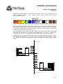
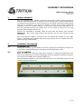
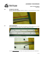
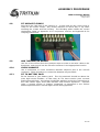
ASSEMBLY PROCEDURE
CMU Cell Sense Wiring
TRI67.006 ver 3
1 August 2012
4.8
FIT MICROFIT CRIMPS
Strip back the CMU end of the cable by 2 – 2.5mm and use the correct tool to
crimp on the molex crimps. Pay careful attention to which way is 'up' when
orienting the crimps and the housing. The following photo shows the correct
relationship. Refer to Appendix A for component sources and Appendix B for
crimping instructions.
4.9
ADD THERMISTOR WIRING
Use one of the offcuts from the previous steps to make a two-wire cable to the
thermistor, and crimp it into the microfit connector in the appropriate location.
4.10
CHECK HARNESS
Use a multimeter to check resistance between adjacent pins in the microfit
connector. There should be no connection between any terminals.
4.11
FIT TO BATTERY PACK
Fit the harness to your battery pack. The ring terminals should be above the
main high-current busbars, so that they do not have traction pack currents
flowing through them. Use spring or belleville washers so that the connections to
the cells remain tight, even with vibration and thermal expansion. Consider
using a contact grease or jointing compound, as described in the Tritium
Wavesculptor200 user's manual high-current wiring appendix.
8 of 10