1
GeoSIG Ltd
AC-23 Accelerometer Manual
GS_AC-23_UserManual_V08.doc/18.03.2011
Page 6
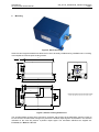
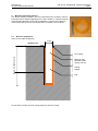
The accelerometer has single-bolt, 3-feet-levelling mechanism.
The surface should have a scribed north/south orientation line accurately surveyed from reliable markers.
The X-axis of the sensor has to be pointed to East or to any other main direction of the structure to monitor.
One M8 expanding nut rock anchor must be used for the sensor fixation.
3
Theory of operation
3.1 Introduction
The AC-23 sensor package is a triaxial accelerometer designed for free field and industrial applications
regarding STRONG-MOTION earthquake survey, monitoring and research. This sensor is well suited for
applications where a high sensitivity is required.
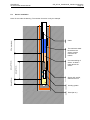
The AC-23 sensor can be optionally installed into a rugged protective housing. This optional protective
housing is in stainless steel for optimal environmental resistance. As option, the protective housing could be
executed with an IP68 grade for Free field location where the possibility exists of housing submersion.
The sensor could be installed on floor or wall with a modification of the axis organization. With the help of the
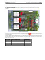
TEST LINE, the complete sensor can be very easily completely tested. Full scale can be field selected by the
user with jumpers.
3.2 Principle
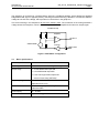
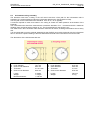
The accelerometer is based on a geophone mass-spring system with electronic correction. This type of
sensors gives a very good stability in temperature and aging because of the very simple principle. It uses a
damped mass spring oscillator called "Geophone" to convert seismic movement into electrical value
proportional to the velocity. In a graphic with constant acceleration, the geophone response will present a
maximum at the frequency called "Natural Frequency" which is the resonant frequency of the mass-spring
oscillator. Above and below this point, the response will decay with one pole slope (±20 dB / decade). The
corrector will over-damp the geophone by applying a voltage with opposite polarity over the geophone and
the output response will be flat and proportional to the acceleration in this frequency band.
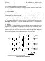
Pulse
scaling
Test input
Motion on
the X axis
geophone
4.5 Hz
Feedback
amplifier
Low pass
filter
Output
amplifier
Differential
Output to
recorder
Motion on
the Y axis
geophone
4.5 Hz
Feedback
amplifier
Low pass
filter
Output
amplifier
Differential
Output to
recorder
Motion on
the Z axis
geophone
4.5 Hz
Feedback
amplifier
Low pass
filter
Output
amplifier
Differential
Output to
recorder
+8 V
-8V
Power
supply
9/15 Vdc
Note : all inputs, outputs & power supply entry are surge protected.
Figure 4 AC-23 Sensor block diagram