1
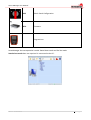
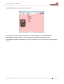
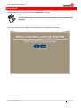
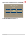
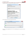
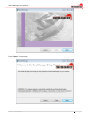
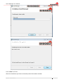
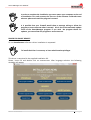
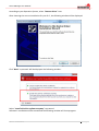
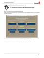
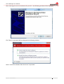
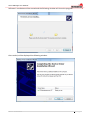
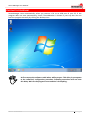
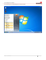
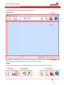
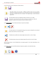
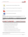
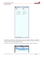
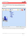
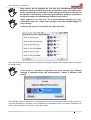
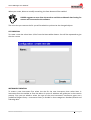
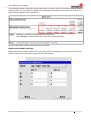
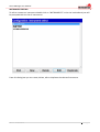
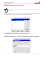
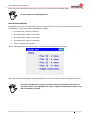
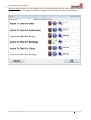
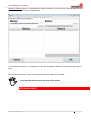
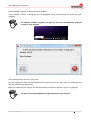
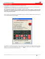
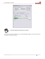
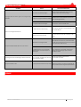
SW ver.4.0.0.0
PORTABLE DATALOGGER SOFTWARE
Smart Manager
User Manual
rev.2 -31.01.2013-
Smart Manager User Manual
INDEX
INTRODUCTION
Pag.4
SMARTMANAGER
Pag.5
SYSTEM REQUIREMENTS
Pag.8
Hardware
Pag.8
Software
Pag.8
INSTALLATION
Pag.9
Driver for Smart Remote
Pag.15
Driver for datalogger firmware upgrade (DFUs)
Pag.18
STARTING THE PROGRAM
Pag.21
PROGRAM DESCRIPTION
Pag.23
Main window
Pag.23
Toolbar
Pag.23
Status bar
Pag.25
Repository window
Pag.26
STARTUP OPERATION
Pag.27
MAIN WINDOW CONTENTS
Pag.28
ON LINE MODE
Pag.28
STAND ALONE MODE
Pag.29
Synchronization process
Pag.30
OBJECTS
Pag.32
CREATION MODIFICATION AND DELETION OF OBJECTS
Pag.33
Site creation
Pag.34
Instrument creation
Pag.34
Standard instrument creation
Pag.36
Biaxial instrument creation
Pag.38
Vibrating Wire instruments
Pag.39
Rev.2 -31.01.2013-
2| P a g e
Smart Manager User Manual
Instrument editing
Pag.40
Worklist creation
Pag.41
Multiplexer creation
Pag.42
Switch panel creation
Pag.46
ARCHIMEDE ONLY
Pag.47
Tube creation
Pag.47
Probe creation
Pag.48
Probe editing
Pag.51
COPY AND PASTE
Pag.52
EXPORTING DATA
Pag.52
INCLINOMETER TESTS
Pag.54
EXPORTED FILE FORMATS
Pag.54
PROGRAM OPTIONS
Pag.55
SOFTWARE UPDATE
Pag.58
FIRMWARE UPGRADE
Pag.60
TROUBLESHOOTING
Pag.62
LICENSE
Pag.63
Copyright
Pag.63
Use of the product
Pag.63
Updates to the product
Pag.63
Responsibility
Pag.63
Legal protection
Pag.63
Rev.2 -31.01.2013-
3| P a g e
Smart Manager User Manual
INTRODUCTION
SmartManager Suite is a suite of programs designed to work together and it is composed of
following modules:
SmartManager
SmartMonitor
SmartExport
SmartRemote
SmartManager is a software designed to run under Windows OS to manage all aspects of
Archimede, Leonardo, new Leonardo and Galileo portable Dataloggers (DLs).
To use SmartManager you should be familiar with the use of DLs. Read the DLs
Manuals before the use.
SmartManager synchronizes the data stored on your PC with data present in the DL and manages
creation and changes of data.
SmartMonitor appears as a small icon on the tray bar and monitors the USB ports for the
connection of a DL. It has the function to automatically launch SmartManager.
If SmartManager does not start automatically when you connect a DL, check
your tray icon bar to ensure SmartMonitor is running.
SmartExport is designed to manage in a friendly manner the reading’s export in Microsoft Excel or
text format so that data can be easily processed with other tools.
See the manual for details.
SmartRemote has been designed to support remote diagnosis and to assist customers in basic
operations.
Rev.2 -31.01.2013-
4| P a g e
Smart Manager User Manual
SMART MANAGER
The main goal of SmartManager is to keep data on your PC and the ones on the DLs, synchronized.
The DL memory is organized as a storage disk. The disk contains folders and files: each folder
represents a “SITE” and contains all files related to it. Each kind of file on a DL is identified by an
icon and associated to specific actions.
Also if the memory’s maximum capacity is remarkable, DL export and synchronization speed with
the PC depends on the internal data quantity.
We advise not to charge exceedingly DL’s memory and to use it ONLY to save the
DL’s files
Icon
Rev.2 -31.01.2013-
Extension
Description
.SGR / .SGT
Readings of all site instruments
SGR file are all readings associated to a site excluded
inclinometer tube test readings.
SGT files are inclinometer tube test readings. Usually they come
in form of TTT-NN.SGT where TTT is the name of tube and NN is
the test sequence number (01, 02, etc.).
.SGP
Inclinometer Tube Configuration.
.SGI
Instruments and Probes Configuration.
.SGW
Worklist Configuration.
.SGM
Multiplexer Configuration (also for digital inclinometers chains).
5| P a g e
Smart Manager User Manual
.SGS
Switch Panel Configuration.
.DFU
Firmware.
Program Icon.
SmartManager has two operation’s mode: Stand-alone mode and On line mode.
Stand-alone mode does not require a DL connected to the PC:
Rev.2 -31.01.2013-
6| P a g e
Smart Manager User Manual
On line mode requires a DL connected to the PC.
To connect DLs you must use an USB cable; see “Startup operation” paragraph for details.
Once DLs are connected to the PC, they are detected as an external USB Storage Disk.
SmartManager software automatically detects connections of DLs and starts the synchronization
process.
Rev.2 -31.01.2013-
7| P a g e
Smart Manager User Manual
SYSTEM REQUIREMENTS
Hardware
Description
Minimum
Recommended
Microprocessor
Pentium 1 GHz
Pentium 2 GHz
Memory
512 MB
2 GB
Hard Disk Free Space
50 MB
500 MB
Monitor
800x600 16bit color
1024x768 24bit color
1 Free USB Port
Software
Description
Supported
Operating System
XP/ Vista x86 / Seven x86 x64
.NET (Included in setup .NET 4.0)
4.0 or newer
Rev.2 -31.01.2013-
8| P a g e
Smart Manager User Manual
INSTALLATION
In order to install the software, insert the CD supplied with DL. The installation process should start
automatically, otherwise please execute autostart.exe in CD root.
The installation process and the first run of the program requires administrative
privileges.
The following window will appear for the selection of the installation language:
Rev.2 -31.01.2013-
9| P a g e
Smart Manager User Manual
Following a new selection window will be shown for the selection of the software to install:
Once “Start program installation” is selected the installation will start.
Rev.2 -31.01.2013-
10| P a g e
Smart Manager User Manual
The software is based on .NET 4.0 technology. If your PC is not equipped with this software, the
setup process will ask you to proceed with the installation of .NET 4.0:
After accepting the user license the setup process will start.
If your PC is already equipped with .NET 4.0 the SmartManager Suite setup process will start
immediately.
Rev.2 -31.01.2013-
11| P a g e
Smart Manager User Manual
Press “Next>” to continue
Rev.2 -31.01.2013-
12| P a g e
Smart Manager User Manual
Select the desired folder and press “Next>”
Press “Next>” to continue
Rev.2 -31.01.2013-
13| P a g e
Smart Manager User Manual
Press “Close” to finish.
After the installation you have to manually close the installer window.
Rev.2 -31.01.2013-
14| P a g e
Smart Manager User Manual
In order to complete the installation you must restart your computer at the end
of installation. For each account, the first run of the software could take some
minutes: please wait until the program is started.
It is possible that your Firewall would show a message asking to allow the
program to access Internet when is started : this is due to the automatic update
check of the SmartManager program. If you wish the program checks for
updates, you must allow the program to access Internet.
DRIVER FOR SMART REMOTE
To use SmartRemote software a driver installation is requested.
To install the driver is necessary to have administrative privileges
This driver is contained in the supplied installation CD.
Please, insert CD and double click on autostart.exe. After language selection the following
windows will appear:
Rev.2 -31.01.2013-
15| P a g e
Smart Manager User Manual
According to your Operative System, select “Remote driver” item.
After choosing the correct installation for your O.S., the following window will be displayed:
Click “Next” to proceed. Will be displayed the following window:
Select “Install this driver software anyway” to proceed.
Software’s installation will be started and the following window will show progress:
Rev.2 -31.01.2013-
16| P a g e
Smart Manager User Manual
Once ended the installation, will be displayed the following window:
Rev.2 -31.01.2013-
17| P a g e
Smart Manager User Manual
DRIVER FOR DATALOGGER FIRMWARE UPGRADE (DFUs)
To install the driver is necessary to have administrative privileges
This driver is contained in the supplied installation CD.
Please, insert CD and double click on autostart.exe. After language selection the following
windows will appear:
According to your Operative System, select “Firmware Upgrade Driver” item.
Rev.2 -31.01.2013-
18| P a g e
Smart Manager User Manual
After choosing the correct installation for your O.S., the following window will be displayed:
Click “Next” to proceed. Will be displayed the following window:
Select “Install the software from the driver” to proceed.
Rev.2 -31.01.2013-
19| P a g e
Smart Manager User Manual
Software’s installation will be started and the following window will show the progress:
Once ended, will be displayed the following window:
Rev.2 -31.01.2013-
20| P a g e
Smart Manager User Manual
STARTING THE PROGRAM
SmartManager starts automatically when you connect a DL to an USB port of your PC. If the
program does not start automatically, check if SmartMonitor is shown in your tray bar. You can
start the program manually by clicking the desktop icon:
At first startup the software could take a while to open. This delay is consequent
to the software’s configuration procedure. Following executions will not have
this delay. Wait for the program’s start and don’t do anything.
Rev.2 -31.01.2013-
21| P a g e
Smart Manager User Manual
Or by selecting the corresponding icon in the start menu:
Rev.2 -31.01.2013-
22| P a g e
Smart Manager User Manual
PROGRAM DESCRIPTION
SmartManager has two windows: Main and Repository.
Main window
TOOLBAR
DATA
STATUSBAR
Main window is composed of three parts: Toolbar, Data and Status-bar.
Toolbar
Located at the top of the main window is divided in three sections: File, Action and Tools.
FILE SECTION
Rev.2 -31.01.2013-
ACTION SECTION
TOOL SECTION
23| P a g e
Smart Manager User Manual
In the File section you can find Open and Save buttons.
The Open button lets you open a different location from the one currently
selected. For example this button can be used when more DLs are connected and
you want to switch from one to another. This button keeps trace of the last
opened DLs.
The Save button stores any modification done on the DLs or on PC data .
This button is not active for actions that act directly on the disk (e.g. when you
duplicate or delete a site, when you rename or delete a device).
In the Action section you can find three buttons: New, Edit and Delete.
The New button can be expanded showing all new action allowed for the selected
object (from the DL or from the PC data).
The Edit button modifies the selected object (from the DL or from PC data)
The Delete button removes the selected object (from the DL or from PC Data).
Some of these button can be disabled (they can appear grayed in this case) depending on the
selected object.
In the Tools section you can find four buttons: Repository, Options, Info and Online Help.
Rev.2 -31.01.2013-
24| P a g e
Smart Manager User Manual
The Repository button lets you open the Repository window.
The Options button lets you change the behavior of the program itself.
The Info button shows program version and other useful information.
The Online Help shows help about program.
Status bar
The Status bar is located at the bottom of the main window and shows some information about
the DL connected to the PC or the copy of a DL stored in archive data (Repository).
Sisgeo DL
We can find: Type , Firmware Version , Name, Serial Number, Calibration Date, Language and Free
Memory.
1
2
3
4
5
6
7
Sisgeo DL
1. Type of DL: Archimede, Leonardo, New Leonardo or Galileo.
2. Firmware Version is the current firmware version of the DL.
3. Name is the descriptive name given by the user to the DL.
4. Serial Number is the number given by Sisgeo.
5. Calibration date is the time when the DL has been calibrated.
6. Language is the actual language being used for the user interface by DL.
7. Free Memory is the quantity of free space available in the DL memory.
When you are working in off-line mode, information are taken from the archive: e.g. Free Memory
refers to the hard disk free space.
Rev.2 -31.01.2013-
25| P a g e
Smart Manager User Manual
Repository window
DL_name_1
DL_name_2
DL_name_3
DL_name_4
Archimede
Leonardo
newLeonardo
Galileo
This window is usually closed. When you open it from the Repository button, the Repository
windows is located at the right side of the Main window and contains a list of the DLs stored in the
PC memory. For each DL are shown Name and Type
To remove a DL from repository right click on the name of DL and select “Remove Datalogger”.
Rev.2 -31.01.2013-
26| P a g e
Smart Manager User Manual
START UP OPERATIONS
SmartManager keeps a copy of DL data present in the DL; since no DL has been connected at first
run, SmartManager window is empty. To start using the program you need to connect a DL with
the USB cable to your PC. Proceed as follows:
1) If the SmartManager program is running, please close it.
2) Check if the SmartMonitor program is shown in your tray bar; if not, run it from the Start
menu or restart your computer (SmartMonitor should be shown in the tray bar when
Microsoft Windows® starts)
3) Connect a DL with the supplied USB cable to a free USB port of your PC.
4) From the DL Main menu select “4 - Communication” and then “1 – USB Disk”. Wait a few
seconds for the PC to detect the new connected device.
SmartManager program will start and ask if you want to add this DL to the PC archive (Repository).
If you answer “No” you can use SmartManager in Stand-alone mode; if you answer “Yes” you can
still use SmartManager in On line mode.
SmartManager will keep asking this question each time the DL is connected until the answer will
be “Yes”
At the end of the import process the Main window will turn red and a new DL entry will be added
in the Repository window.
Now the program is working in the On line mode.
MAIN WINDOW CONTENTS
Rev.2 -31.01.2013-
27| P a g e
Smart Manager User Manual
The main window of both Online and Stand-alone mode shows the DL memory organized by sites.
ON LINE MODE
The Online mode is activated each time you connect a DL. The Main window will turn red and you
will see a DL image on the left of the Main window. When you are in Online mode all actions take
place on the DL memory. If you are interested only in exporting data you can always use the
program in Online mode only.
Rev.2 -31.01.2013-
28| P a g e
Smart Manager User Manual
STAND ALONE MODE
If you start SmartManager without connecting a DL, you are in Standalone mode. The Main
window will turn blue and you will see a PC image on the left of the Main window. To operate on a
specific DL, double click it in the Repository window. The Main window will display the data from
the selected DL.
When you are in Stand-alone mode all actions take place only on the PC memory (Repository).
Rev.2 -31.01.2013-
29| P a g e
Smart Manager User Manual
SYNCRONIZATION PROCESS
When you connect a DL to your PC through an USB cable, SmartManager checks if that DL is in the
PC archive: if not, it asks to add it.
If a DL is present, SmartManager will check for differences between data stored in the DL and the
archived data (Repository).
Be careful and check which user is connected to the PC: the synchronization is
closed for the account currently in use.
For each object (Site, Reading, Instrument, etc.) there are four options:
1) The objects is both in the DL and in the PC archive and there is no difference.
2) The object is both in the DL and in the PC archive but are different.
3) The object is only in the DL.
4) The object is only on the PC archive.
If there are no differences, nothing is asked; otherwise the program asks what to do. The program
groups differences according to the kind of object (instruments, site, readings, etc). The first time
differences are found, the program will ask what to do. The following actions can be applied:
1) Do Nothing
Do nothing keeps DL and PC archives untouched (the next synchronization will ask again what to
do)
2) Copy From DL to PC
Copy From DL to PC copies all object of a given type from DL to PC when a difference is found.
3) Copy From PC to DL
Copy From PC to DL copies all object of a given type from PC archive to the Datalogger when a
difference is found.
4) Merge Data
Merge data will be applied only for readings and instruments, and will merge data so that, at end
of the synchronization process, the objects on the DL and on the PC will match.
5) Ask User for each object
Ask User for each object will ask what to do for each object.
Rev.2 -31.01.2013-
30| P a g e
Smart Manager User Manual
These options will be displayed the first time that SmartManager finds some
differences between the DL and/or in the PC repository’s data. The choices taken
on the synchronization mode will be saved among the preferences and will not
be required in the following connection/synchronization. Anyway it’s possible to
change this setting from SmartManager software option menu.
Sisgeo suggests to set “Ask User” for all synchronization typology (e.g. Sites,
Instruments, Tubes etc…) apart from “Readings” item where SISGEO suggests to
select “Merge”.
In this way the user are free to select the option each time.
Once these option are selected they are stored in program Options (see Program Options chapter
to change them).
If the probe or instrument configuration has been changed, the following
message is displayed during the synchronization: “Object is different from
archive”
The message is generic because it is not possible to know if the change has been made in the DL or
in the PC (Repository), therefore is very important to remember which is the latest modification in
order to know exactly the direction of synchronization.
Rev.2 -31.01.2013-
31| P a g e
Smart Manager User Manual
OBJECTS
SmartManager program handles all type of objects in the DL. These are the objects and their use:
SITE – This object is the container where all objects that refers to a specific location are stored
INSTRUMENTS – Each site contains a list of instruments used to perform the readings. You can
create as many instruments as you require to be used in a site. The creation of instruments is a
guided procedure, starting from selecting the type of instrument from a library of predefined
instruments.
For Archimede, the probes’ list will be saved in the INSTRUMENTS file located
outside the site.
READINGS – Readings contains all executed readings (except from inclinometer test).
WORKLISTS – Work list is a list of instruments usually read in sequence.
MULTIPLEXERS – Multiplexers are special electronic devices that expand the use of DL to read
multiple cabled instruments; they are normally used with ADK-100 data acquisition units.
Each chain of digital inclinometers is considered as a Multiplexer.
SWITCH PANELS – Switch panels are devices used to manually switch different instruments on one
DL.
PROBES – The removable inclinometers probes are used to perform inclinometer tests.
INCLINOMETRIC TUBES – These objects describe the tubes where are performed inclinometer
tests.
INCLINOMETRIC TEST – These are the tests executed on an inclinometer tube with a removable
inclinometer probe.
Creating some object like Site and Multiplexer do not require saving changes (in
these cases the save button will be not enable).
Rev.2 -31.01.2013-
32| P a g e
Smart Manager User Manual
CREATION MODIFICATION AND DELETION OF OBJECTS
To create a new object you can either use the Toolbar new button or use the contextual menu
clicking the mouse right button while selecting a site or an object.
The creation of each object is guided by a series of windows asking you to fill in the object’s
features.
When the user omits the necessary data, or enters incorrect data, an error
message appears.
Rev.2 -31.01.2013-
33| P a g e
Smart Manager User Manual
When you create, delete or modify something, the Save button will be enabled.
SISGEO suggests to save often the work to avoid the accidental data loosing for
reasons not connected to the software.
The next time you connect the DL you will be asked to synchronize the changed objects.
SITE CREATION
To create a new site select New → Site from the New toolbar button. You will be requested to give
the site a name.
INSTRUMENT CREATION
To create a new instrument first select the site for the new instrument then select New →
Instrument from the toolbar or from the Menu. A series of windows will guide you in the creation
process. First you are asked to select the type of the new instrument. Instrument types are a
predefined Sisgeo Library . Instrument Library is divided in three categories: Standard, Biaxial and
Vibrating Wire.
Rev.2 -31.01.2013-
34| P a g e
Smart Manager User Manual
Standard instruments are all the instruments with a single channel / single axes, whereas Biaxial
instruments have two channels/ two axes. Vibrating Wires instruments are a special kind of
instruments (only Galileo and New Leonardo unit can read them).
Rev.2 -31.01.2013-
35| P a g e
Smart Manager User Manual
STANDARD INSTRUMENT CREATION
After selecting a standard instrument from the Sisgeo’ s library, will be shown the following
Instrument identification dialog:
Fill in Name, Warm-up and Decimals digit. Also check that the name you are using is unique,
otherwise a dialog will warn you and ask to change instrument’s name. By pressing the Next
button the following dialog will be shown.
Click Next and will be shown the following window:
Rev.2 -31.01.2013-
36| P a g e
Smart Manager User Manual
For most instruments the wire colors are predefined, based on the Sisgeo Library Instrument (see
“Appendix A” of DL manuals for details). If you want to change it, select the wire, then select the
first list for plain colors and one in the second for bicolor wires. To remove colors press the delete
key while the colors list is selected.
Once the color wiring scheme is defined, the Calibration dialog will be shown.
Rev.2 -31.01.2013-
37| P a g e
Smart Manager User Manual
In this dialog window is defined the polynomial used to convert from the electrical measure to the
physical value. You can select the grade of the polynomial. Parameters (A,B,C,D) can be found in
the Calibration Report of the instrument.
Click on Save button and the instrument will be created.
BIAXIAL INSTRUMENT CREATION
Biaxial instrument creation follows the same steps used for Standard instruments, but have to be
filled the polynomial conversion parameters for both channel.
Rev.2 -31.01.2013-
38| P a g e
Smart Manager User Manual
VIBRATING WIRE INSTRUMENTS CREATION
For vibrating wires the program will ask for NTC (thermistor) calibration and Gauge parameter (for
µŰ conversion).
NTC
calibration
You should not modify the NTC (thermistor) calibration
Rev.2 -31.01.2013-
39| P a g e
Smart Manager User Manual
INSTRUMENT EDITING
To edit or remove an instrument double click on “INSTRUMENTS” in the site involved and you will
be prompted with the list of instruments.
From this dialog box you can create, delete, edit or duplicate the selected instrument.
Rev.2 -31.01.2013-
40| P a g e
Smart Manager User Manual
WORKLIST CREATION
Worklist are lists of instruments to be read in sequence.
You can have more than one worklist in the same site.
To create a worklist you must first create all the instruments requested for the
worklist.
First you should give a name to the worklist, then will be shown the following dialog box. At the
beginning the list will be empty; in the image, two instrument has been defined.
Use Up and Down buttons to order instruments in the list.
Use Delete to remove instruments from the worklist and Edit to change it.
To add an instrument click Add button; the following dialog will be shown.
To select an instrument click the “…” button: will be shown the list of the current site instruments .
Rev.2 -31.01.2013-
41| P a g e
Smart Manager User Manual
Once you have selected the instrument you can fill in the Position and Notes fields.
An instrument can’t be added twice.
MULTIPLEXER CREATION
Multiplexers are lists of instruments that are connected and read with special electronic device
(multiplexer). There are 4 types of Multiplexer boards:
•
32 channel for 2 wires instrument,
•
16 channels for 2 wires instrument,
•
32 channels for 4 wires instrument,
•
16 channels for 4 wires instrument.
•
Chain of digital inclinometers
The first dialog box will ask you to select a name for the multiplexer and its type.
After you click the Next button, will be displayed a list of instruments for each multiplexer channel.
To create multiplexer you have to create first all the instruments required for it.
This precaution is not applicable for chains of digital inclinometers: please read
the DL manuals for details
Rev.2 -31.01.2013-
42| P a g e
Smart Manager User Manual
Use “Up” and “Down” buttons to select the channel for the choosen instrument. Click “Delete” to
remove an instrument from a multiplexer.
To select the instrument connected to a channel, click the “Edit” button; the following dialog box
will be shown.
Rev.2 -31.01.2013-
43| P a g e
Smart Manager User Manual
To select an instrument click on the “...” button: the list of current site instruments will be shown.
Once you have selected the instrument you can fill in the position and notes field.
Instrument can’t be added twice.
Rev.2 -31.01.2013-
44| P a g e
Smart Manager User Manual
After selecting the instrument, click Save to return to the multiplexer list.
If “digital inclinometers” is selected as type of multiplexer, will be shown only the following dialog
box:
Please read the DL manual for details.
Rev.2 -31.01.2013-
45| P a g e
Smart Manager User Manual
SWITCH PANEL CREATION
Switch Panels are similar to Multiplexers but the selection of channels is made manually switching
a selector and positioning a rotor switch.
As for Multiplexers and Work lists, a name will be required and a list of instruments ordered by
selection and position will be shown.
To add a new instrument click the Add button; the following dialog box will be shown.
Please read the DL manuals for details.
After selecting an instrument using “...” button, you must provide the Selector and Position value.
Rev.2 -31.01.2013-
46| P a g e
Smart Manager User Manual
ARCHIMEDE ONLY
Rev.2 -31.01.2013-
47| P a g e
Smart Manager User Manual
TUBE CREATION
To create a new inclinometer tube, select the SITE where the tube will be created and click the
New button located in the toolbar or press the right mouse button on SITE and select New →
Inclinometer Tube from menu.
You will be requested to fill in the following fields: Name, Length and Step. You can also define the
Run of inclinometer tube, Type, Unit of measurement and some Notes.
Please read the DL manuals for details.
Rev.2 -31.01.2013-
48| P a g e
Smart Manager User Manual
PROBE CREATION
To create a new inclinometer probe, select “PROBES” in the Main window and use the “New”
button located in the toolbar or press the right mouse button on PROBES and select New → Probe
from menu.
A procedure will guide you through the process of creating a new probe.
First you will be asked to select the kind of of probe,from the Sisgeo probe library (see “Appendix
A” of DL manuals for details).
Once selected, the probe has to be customized.
Rev.2 -31.01.2013-
49| P a g e
Smart Manager User Manual
This customization is not applicable for digital inclinometer probes because the configuration is
already saved on the probe: please, read the DL manuals for details.
Customization of a inclinometer probe lets you select a Name*(max 15 characters), some Notes,
Unit, Warm-up time* and number of Decimal digit* to display.
(*)required
For biaxial probes it is possible to define the calibration as two Polynomial or as a specific Probe
calibration.
Probe calibration requires you to fill Span, Electrical Offset, Mechanical Offset and Cross Axis
parameters for each probe axis. See the Sisgeo Calibration Report to retrieve these parameters.
Rev.2 -31.01.2013-
50| P a g e
Smart Manager User Manual
Polynomial calibration requires you to fill in a set of coefficients for each probe axis. The degree of
the polynomial may be selected using the list at the top (use down arrow to change).
Rev.2 -31.01.2013-
51| P a g e
Smart Manager User Manual
PROBES EDITING
To edit inclinometer probes you can double click on the “PROBES” labels you will find in the Main
window. A list of all available probes is shown
The buttons at the bottom allows to : Create new probe (New), delete selected probe (Delete),
change probe’s setting (Edit) or duplicate the selected probe (Duplicate); double clicking on the
chosen probe will open the probe’s configuration in editing mode.
COPY AND PASTE
Rev.2 -31.01.2013-
52| P a g e
Smart Manager User Manual
Right clicking on any object will display a popup menu. In the popup menu you can find “Copy” and
“Paste” command. The “Copy” command will copy to the clipboard the selected object. The
“Paste” command will move the object from the clipboard to the selected position.
Example 1: If you have configured a site with some instruments you can copy instruments from
one site to another.
Example 2: You have two DLs and you can copy a site from one to another
Start manually SmartManager and select from Repository the DL containing the site you want to
copy. Right click and select copy. From the Repository, open the DL where you want to copy the
site. Select any object and right click on paste. The site will be copied from one DL to the other.
Next time you will connect second DL you will be asked to sync the new copied site.
It is also possible to copy some object from a site or DL, to another using “Drag and Drop”
EXPORTING DATA
Instruments readings are saved separately on each site. Every site has its own readings. All
readings coming from single instruments or instrument array (Multiplexer, Switch panel and
Worklist) are stored together. SmartManager exports readings in Microsoft Excel format separating
reading from different sources (multiplexers, manual readings etc) in different Microsoft Excel
sheets. To export data, double click on readings. A dialog window will ask you for the place where
to save Microsoft Excel file with the exported data. By default, the name of the export file is the
name of the site.
Rev.2 -31.01.2013-
53| P a g e
Smart Manager User Manual
Rev.2 -31.01.2013-
54| P a g e
Smart Manager User Manual
INCLINOMETER TESTS
Readings from inclinometer tests are stored separately . Each test is shown under the tube
where it has been performed. Double clicking on a inclinometer test, will display a dialog asking
where to save the exported file.
The exported format depends on the kind of inclinometer test executed
It is also possible delete inclinometer tests: please, be careful to avoid accidental
deletion.
EXPORTED FILE FORMATS
The exported files for readings are in Microsoft Excel format. The Microsoft Excel File will have one
sheet for manual readings and one sheet for each multiple reading device (Multiplexer, Worklist
and Switch Panel).
Inclinometer tube test data are exported in different format depending from the of test:
•
inclinometer test and spiralometric tests are exported in Sisgeo format to be used with
analysis software (“Incli2” program for example).
•
T-REX is exported in Microsoft Excel format, ready to be processed with analysis software
(Sisgeo “T-REX Analyzer” program for example).
This is an example of Microsoft Excel file generated by reading from a Galileo Datalogger:
Rev.2 -31.01.2013-
55| P a g e
Smart Manager User Manual
PROGRAM OPTIONS
Rev.2 -31.01.2013-
56| P a g e
Smart Manager User Manual
By clicking the gear button in the tool bar you can access program options.
There are three kind of options: General, Synchronization, Backup & Restore.
General options let you change the interface language of the program (English and Italian are
implemented).
After the change, restart program to apply.
Rev.2 -31.01.2013-
57| P a g e
Smart Manager User Manual
Synchronization options let you change how the synchronization process takes place. For each
group of objects it is possible to establish the default action to execute during synchronization.
Rev.2 -31.01.2013-
58| P a g e
Smart Manager User Manual
Backup & Restore options are designed to make a backup or recovery from a backup copy of DL
data present in the PC archive (Repository).
For the Backup process it is required to select the destination folder for the compressed copy of
data.
For the Restore process, select the compressed file with data to be restored.
Restoring data will overwrite any data in the archive.
SOFTWARE UPDATE
Rev.2 -31.01.2013-
59| P a g e
Smart Manager User Manual
SmartManager regularly checks Internet for updates.
If any update is found, a dialog box will be displayed asking to download and install the new
software.
To complete software upgrade you have to close the SmartMonitor program
running in your tray bar.
The update process can take a long time.
First the installation files are downloaded from internet to your PC, then they are uncompressed
and the installation process starts.
Before to install the new version, will be requested to remove the previous version of program.
You have to close SmartMonitor Program located in your tray bar.
Rev.2 -31.01.2013-
60| P a g e
Smart Manager User Manual
If you have no Internet access, you can obtain software updates directly from SISGEO Assistance.
SmartManager checks for new software update every 7 Days from the last
inspection. To force Software update check Start SmartManager keeping
pressed “SHIFT” key
Updating software will not delete any stored Datalogger data.
Data is stored in a general document directory, this directory may change according to Operative
System and language installed.
On Windows XP it is located in
“C:\Documents and Settings\All Users\Application Data\Sisgeo\SmartManager\Repository”
On Windows Vista/Seven it is located in
“C:\ProgramData\Sisgeo\SmartManager\Repository”
To find easily this directory search your hard disk for “SmartManagerOptions.xml” file
For Dataloggers and data backup, make a copy of this directory.
Rev.2 -31.01.2013-
61| P a g e
Smart Manager User Manual
FIRMWARE UPDATE
The firmware is the program that internally controls each DL.
SmartManager will check every time you connect a DL if a newer version of the firmware is
available; in that case it will request to execute a firmware update.
The comparison between the DL firmware versions and the PC version is done at each
connection. The comparison between the DL firmware versions and the Network version is done
every 7 days to the last check.
New firmware are automatically downloaded during the software update process and they can
also be obtained directly from SISGEO.
To update the firmware you need to switch off the DL, and switch it on again pressing the keys
shown (1, 3, 9, enter and ON/off key). When the DL shows a blue screen, press the “UPGRADE”
button on the PC screen to start the process.
Rev.2 -31.01.2013-
62| P a g e
Smart Manager User Manual
At the first update, the PC will ask you for drivers.
Once ended the firmware upgrade process, close SmartManager program, switch off DL and switch
it on again to complete the process.
Rev.2 -31.01.2013-
63| P a g e
Smart Manager User Manual
TROUBLESHOOTING
Problem
Cause
Recommended action
User account with limited privileges
Ask your system's administrator and remake the
installation with administrator privileges
The PC does not support software installation
Verify that the PC has the minimum requirements
(see Smart Manager Manual )
The supplied CD has been damaged
Test the CD on another CD-ROM reader
The USB connection could be wrong
Check that the USB cable is inserted well both in the
PC and in the DL port
USB drivers do not start correctly
Disconnect and connect the DL. Eventually, restart
the PC.
Software does not recognize the DL
Check that the DL is turned on, connected and that
the USB communication function has been activated (
for the procedure see DL manual )
The software points to an incorrect path,
probably because of a manual setup on a
different path
Try to synchronize a second time; start the Start
Manager and select through "Open" the letter
associated to the DL
Connecting the DL the Smart Manager software starts twice
At the first connection of a new DL, the
driver's automatic installation can cause the
double start of the sofware
Close the open windoes and restart the
communication procedure.
The synchronization is slow
Too many elements have been set up on the SISGEO recommends to synchronize periodically DL
DL
and PC, instead to make a single full synchronization
The program does not install or gives error messages during
installation
The DL is not recognized from the PC
The synchronization between DL anc PC is not correct
LICENSE
Rev.2 -31.01.2013-
64| P a g e
Smart Manager User Manual
Sisgeo grants the purchaser of this product the non-exclusive and non-transferable rights detailed
below, in return for payment of the required price. The customer has agreed to be bound to the
terms fixed in this license regarding the installation and creation of copies or any other use of the
product. The license for use does not grant the customer ownership of the product, but only the
right to use it according to the terms fixed in this license. Sisgeo may modify the conditions of the
license for use at any time.
COPYRIGHT
The client acknowledges that:
1. the product is the property of Sisgeo as copyright holder as well as indicated within the
product, and that such rights are subject to national law and international treaties on
copyright.
2. all the rights, title, and interest in this product are and shall remain Sisgeo’ s, including
intellectual property rights.
USE OF THE PRODUCT
The customer may install and use a single copy of this product on a single workstation, exclusively
for the customer's own internal personnel. Conditions of installation permitting the sharing of the
product by multiple workstations must be approved by Sisgeo. The customer agrees to make A
SINGLE COPY of the product file for the purposes of backup. The text of the product may not be
modified, translated, adapted, or redacted. The only version of the text which has valid standing is
that preserved in Sisgeo’ s archive. PARTIAL reproduction of the product is authorized only on
documents for the exclusive internal use of the customer. It is prohibited to give the product, in
license or in fact, to resell it, distribute it, or cede it in any respect in any of its parts, whether in
the original or a copy.
UPDATES TO THE PRODUCT
The product purchased is the version in force at the moment of sale. The product is updated when
necessary with the publication of new editions or updates. Sisgeo is not obligated to advise the
customer of publications of variants, corrected errors, or new editions which modify, update, or
entirely replace the product; it is therefore important for the customer to ascertain that he or she
is in possession of the latest edition and any updates.
RESPONSIBILITY
Neither Sisgeo nor any of its managers, employees, or distributors can be considered responsible
for any eventuality which may derive, result, or be in any way related to the possession or use of
the product on the part of the customer. Such responsibility shall remain with the customer.
LEGAL PROTECTION
The customer agrees to provide Sisgeo with all information necessary to guarantee the full respect
of the terms of this agreement on the part of third parties. In case the actions of third parties place
in doubt the observance of the terms of this agreement, the customer undertakes cooperation
with Sisgeo to guarantee observance. Sisgeo reserves the right to take any legal action whatsoever
towards the customer to safeguard its own rights in any jurisdiction in which a violation of this
agreement has taken place. The agreement is subject to law in force in Italy and the competent
court for any controversy shall be that of Milan.
Rev.2 -31.01.2013-
65| P a g e