1
GeoSIG Ltd
AC-23 Accelerometer Manual
GS_AC-23_UserManual_V08.doc/18.03.2011
Page 7
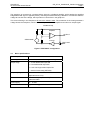
The geophone is connected in a resistor bridge, driven by a feedback amplifier, which applies the amplified
bridge differential signal in opposite polarity. The bridge is balanced during calibration. The test-line shifts the
voltage at one side of the bridge, which produces a current flow in the geophone.
This current flowing in the Geophone will move the seismic mass. The movement of the mass generates a
voltage across the Geophone, which is detected by the differential amplifier and induces an output signal.
Feedback loop
Amplifier
OUTPUT
GEOPHONE
Inverter
TEST LINE
Figure 5 TEST INPUT configuration
3.3
Basic specifications
Detailed specifications
AC-23
Input range
Acceleration, ±0.2, ±0.5, ±1.0 g or ±2.0 g
Output range
0 ± 10 Volt differential output OR
0 ± 5 Volt differential output OR
2.5 ± 2.5 Volt single-ended output OR
0 – 20 mA Current-loop (OPTION)
Frequency range
from 0.1 Hz to 50 Hz
(Optional from 0.2 Hz)
Protections
All connectors pins protected by Transzorb
diodes and VDR
Power supply
10 – 15 VDC
Current drain
Typical 30 mA @ 12 VDC