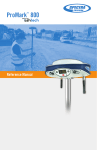
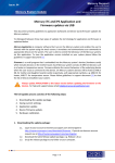
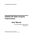
1
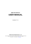
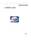
USER’S MANUAL
Settop RadioLink
Settop DataConvert
Rev. March
1
Index
SETTOP RADIO-LINK ....................................................................................................................... 2
Batteries ........................................................................................................................................ 3
Radio-Link ...................................................................................................................................... 4
Led indicators ............................................................................................................................ 5
Communication Ports................................................................................................................. 5
BASE mode ................................................................................................................................ 6
REPEATER Mode ........................................................................................................................ 8
SETTOP REPEATER Mode............................................................................................................ 9
ROVER mode............................................................................................................................ 11
Software Settings ......................................................................................................................... 12
Radio-Link – ADLCONF Settings .................................................................................................... 13
Factory Default Settings ........................................................................................................... 13
Identification ........................................................................................................................... 14
Radio Link ................................................................................................................................ 15
Serial Interface ......................................................................................................................... 17
Frequencies ............................................................................................................................. 18
Combinations supported .......................................................................................................... 19
2
SETTOP RADIO-LINK
This guide provides a general overview of the basic characteristics and instructions for
setting up the Settop RADIO-LINK receiver and being able to operate with it in a simple way.
Step 1: Fully charge the batteries. Screw the antenna and connect the batteries.
Step 2: Set up the radio in the manner desired. Learn about the functionalities of the LEDS.
ADDITIONAL INFORMATION
Thank you for the trust you have invested in the SETTOP brand for carrying out your
professional activities.
Remember that you must refer to our website www.settopsurvey.com for information on
settings, quick guides, etc.
The purchase of the equipment includes the warranty in accordance with the equipment
supplied (labor and replacement of defective parts), starting on the date of delivery. The
SETTOP Customer Service will help you with any problem related to your new device. You
may contact us at [email protected]
Likewise, purchasing the equipment includes the Customer Service (during the
warranty period), starting on the date of delivery. The SETTOP Customer Service will help
you with any doubt regarding the handling of the equipment, its setting and its start-up. You
may contact us at [email protected]
Once the warranty has expired, you may opt for the annual warranty extensions. Do not
wait for the expiration of the warranty to contract the extension.
3
Batteries
The system is powered by 2 7.2V Lithium-Ion batteries, with an approximate autonomy of 11
hours in basic mode.
The two batteries must be inserted by sliding them through the flaps.
To extract the batteries, press on lower flaps, sliding the battery in the opposite direction.
One may also use a 12V-18V external battery using AUXPORT.
4
Radio-Link
The SETTOP Radio-Link system offers numerous setup possibilities. It may be set up in:
● Base Mode. The SETTOP Radio-Link is connected to a GNSS receiver in order to
transmit corrections.
● Repeater Mode. The SETTOP Radio-Link is set up to repeat the signal of a base station.
● SETTOP Repeater Mode. The SETTOP Radio-Link is connected to a SETTOP Repeater
device so as to transmit the differential corrections via radio received through an NTRIP
protocol. ,
● Rover Mode. The SETTOP Radio-Link is connected to a GNSS receiver so as to receive
corrections.
5
Led indicators
Once the SETTOP Radiolink device has been suitably connected.
•
•
•
LED TX (Transmit) must be constantly flashing.
LED RX (Receive) must be off when in Base mode*; in Repeater mode, it must flash,
alternating with the TX.
LED POWER must be permanently on when it is being powered.
*NB: In Base mode, the LED might flash if there are external sources of interference.
Communication Ports
•
Aux PORT : this makes it possible to set up the Settop Repeater if the Settop
Radiolink is attached. Also allows to use a 12V-18V external battery
6
BASE mode
Connect the SETTOP Radio-Link to a GNSS receiver to transmit corrections.
To proceed to the connection of the SETTOP Radio-Link, you have numerous options:
Method 1:
The GNSS receiver is powered by an internal battery. The setup requires:
● 1 SETTOP Radio Link
● 2 Lithium Batteries
● 1 Radio antenna
● 1 Power cord
7
One end of the Power cord is connected to the Radio Link Port of the SETTOP Radio-Link
device and the other end is connected to the GNSS receiver
Method 2:
The GNSS receiver is powered by an external battery.
The setup requires:
● 1 SETTOP Radio Link
● 1 Radio antenna
● 1 Power cord
● 1 System cable
One end of the Power cord is connected to the GNSS receiver and the other end to the
SETTOP battery.
As for the system cable, one end is connected to the second connector of the SETTOP
battery and the other end to the Radio Link Port
Once the SETTOP Radio-Link device has been correctly connected to the GNSS receiver,
the next step is that of setting up the base. Following the setup, the LED TX must be
constantly flashing. The LED RX must be off. The LED POWER must be permanently on
when it is being powered.
8
REPEATER Mode
The SETTOP Radio-Link is set up to repeat the signal of a base station.
The setting of the radio in repeater mode must be carried out before the field trip.
When the batteries are connected, the radio automatically turns on, starting to receive the
corrections from the base and to immediately transmit them, expanding radio range.
The LED TX must be constantly flashing; the LED RX must also be flashing and alternating
with the TX. The LED POWER must be permanently on when it is being powered.
9
SETTOP REPEATER Mode
The SETTOP Radio-Link is connected to a SETTOP Repeater device so as to transmit the
differential corrections via radio through an NTRIP protocol.
The SETTOP Radio-Link adjusts perfectly to the SETTOP Repeater device at the back. By
means of the connectors and two screws, the devices are perfectly and tightly joined.
At the moment of the SETTOP Repeater being turned on, it will be in
charge of automatically setting up the SETTOP Radio-Link. The device
may be placed on a tripod and in an area with GPRS coverage.
10
11
ROVER mode
The SETTOP Radio-Link is connected to a GNSS receiver so as to receive corrections.
Installation:
The ring bracket is fastened to the rod with the set screw. This bracket will keep the SETTOP
Radio-Link stable in the rod.
It is fixed in the Radio-Link with the clamp in the rod. Suggested use
12
Software Settings
In order to set up the SETTOP Radio-Link in the field software, the following setting must be
taken into account.
One must modify/create the field software survey style that one usually employs.
One must select the correct radio Type in the list.
● "Trimble TDL" or "Custom Radio"
Communication speed between the receiver and the radio
● 38400 bps (it must coincide with the speed set in the radio in the Serial Interface tab)
Radio parity must be:
● None
The port of the receiver must be selected in accordance with the receiver used. This setting
is valid both for using the radio as a Base and for Rover.
13
Radio-Link – ADLCONF Settings
In order to connect the SETTOP Radio-Link to the PC and set it up, one must connect the
radio to the Radio Link port and, at the other end, to the RS232/USB Port of the computer.
Accessing the ADLCONF program of Pacific Crest makes it possible to fully set up the radio
(one may need a key or dongle for certain settings).
The last version of the program may be downloaded free of charge at www.pacificcrest.com
Factory Default Settings
14
Identification
The fields in this tab are for information purposes and cannot be edited.
The initial Identification tab contains the information on the radio (firmware, frequency range,
serial number, etc.)
15
Radio Link
In the Radio Link tab, one can set up the characteristics of the radio link (speed, sensitivity,
power level, repeater)
Current channel
One can select the active channel through which the transmissions will be made
Sensitivity
One can choose radio sensitivity. According to the use desired for the radio, one
must select the correct channel, the following being recommended:
Low (in basic mode)
High (in mobile or repeater mode)
16
Repeater
The box must be activated if the radio is to be set up as a repeater.
17
Serial Interface
In the Serial Interface tab, one can set up the communication between the radio and the
collector/PC and the protocol used.
You may choose from the different protocols:
● Transparent with EOT Timeout
● Transparent with EOT character
● Packet Switched
● TRIMTALK 450S
● TRIMTALK II/IIE
● TT450S (HW)
● TRIMMARK 3
● SATEL
● Transparent FST
● South
● Stonex Type 1
● U-Link
18
Frequencies
In the Frequencies tab, one can set up the table for the transmission and reception
channels.
In order to create a specific table of frequencies, it will be necessary to have the key for
creating them. Should you not have that key, you may contact your distributor and request
the table. You will be able to import the file provided by your distributor.
19
Combinations supported
Combinations supported between the different setting options. Not all options are mutually
compatible.
If you attempt an unsupported combination, a message like the following will appear:
20