1
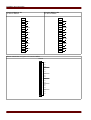
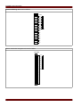
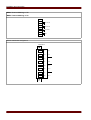
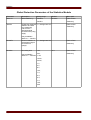
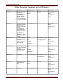
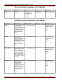
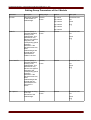
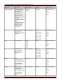
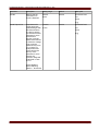
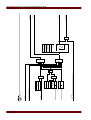
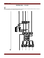
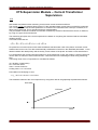
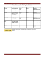
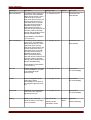
V-Protection Module – Voltage Protection [ANSI 27/59]
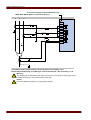
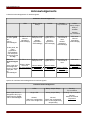
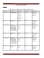
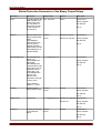
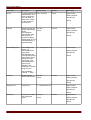
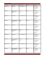
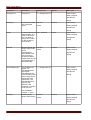
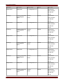
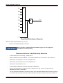
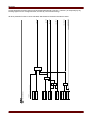
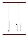
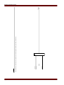
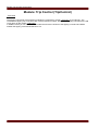
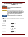
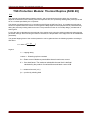
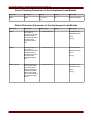
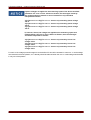
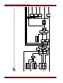
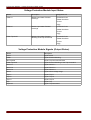
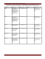
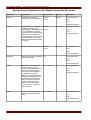
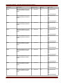
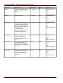
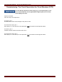
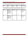
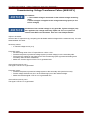
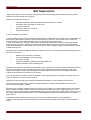
If phase voltages are applied to the measuring inputs of the device and field
parameter »VT con« is set to »Phase-to-neutral«, the messages issued by
the voltage protection module in case of actuation or trip should be
interpreted as follows:
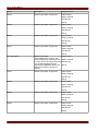
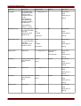
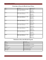
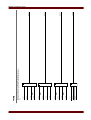
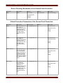
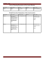
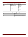
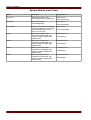
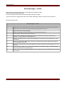
»V[1].ALARM L1« or »V[1].TRIP L1« => alarm or trip caused by phase voltage
»VL1«.
»V[1].ALARM L2« or »V[1].TRIP L2« => alarm or trip caused by phase voltage
»VL2«.
»V[1].ALARM L3« or »V[1].TRIP L3« => alarm or trip caused by phase voltage
»VL3«.
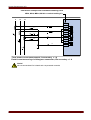
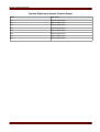
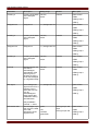
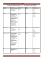
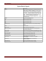
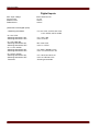
If, however, line-to-line voltages are applied to the measuring inputs and
field parameter »VT con« is set to »Phase to Phase«, then the messages
should be interpreted as follows:
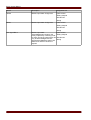
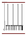
»V[1].ALARM L1« or »V[1].TRIP L1« => alarm or trip caused by line-to-line
voltage »V12«.
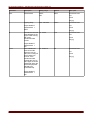
»V[1].ALARM L2« or »V[1].TRIP L2« => alarm or trip caused by line-to-line
voltage »V23«.
»V[1].ALARM L3« or »V[1].TRIP L3« => alarm or trip caused by line-to-line
voltage »V31«
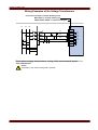
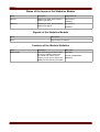
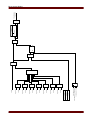
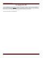
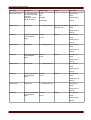
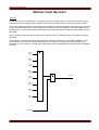
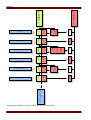
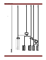
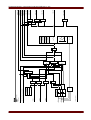
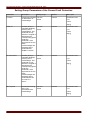
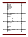
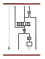
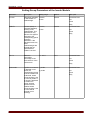
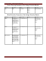
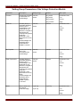
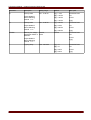
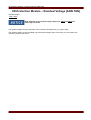
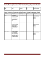
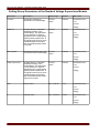
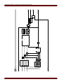
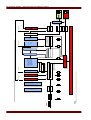
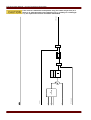
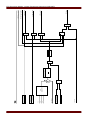
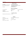
For each of the voltage protection stages it can be defined if it should be actuated in case over- or undervoltage
was detected in all three phases, or if it already should be alarmed when the over- or undervoltage was detected
in only one of the phases.
MRA4 02.08 UK
Page 275