1
EE 2310: Experiment #4
•
Use large functional blocks for your high-level design. That is, since you are designing an 8bit adder, start with a single 8-bit adder block. It does not matter that there is no 8-bit
adder chip. As you move to a more detailed design, this block will be subdivided into actual
hardware (i.e., chips that are available to you).
Don’t forget your physical design limitations – the number of switches and LEDs.
•
Step 2: Take each large functional block and decompose it into actual hardware circuits. As
noted above, you can start on the first steps at home.
Step 3: Build your circuit on the breadboard. Verify the operation of the circuit.
Step 4: Test the cases below and list the results in your lab report. These last two steps must
be done in the lab.
•
•
•
Note: You are building an adder for positive numbers; NOT two’s complement.
Add 85 (01010101) and 42 (00101010) with no carry-in and then with carry-in.
Add 128 (10000000) and 127 (01111111) with no carry-in and then with carry-in. How do
you display the carry out?
Pick a few other binary numbers to add.
Have your TA verify your results and sign your data sheet.
•
•
7. Equipment Disassembly: Disassemble the circuit, replace wires and parts in the kit boxes,
and replace kits in the cabinet. Make sure your work area is clean and have the TA check.
8. Laboratory Report: As usual, your laboratory report should follow the on-line form. In
your write-up, discuss your results. Also include the following items:
•
•
•
Discuss your experience in the laboratory and any problems with the procedure.
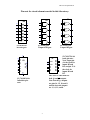
Show the complete design. You do NOT need to show the connections to Power and Ground, nor do
you need to show the circuit outlines.
Discuss any insights gained from the exercises.
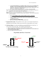
Chip Outlines and Power Connections
Notch
Notch
Ground (0V.)
connection
1
2
3
4
5
6
7
14
13
12
11
Power (+5V.)
connection
Power (+5V.)
connection
10
9
8
1
2
3
4
5
6
7
8
16
15
14
13
12
11
10
9
74LS83 & 74LS75
Chip Outlines
74 LS 04, 08, 32 14-Pin Chips
2
Ground (0V.)
connection