1
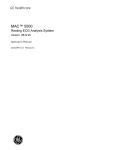
AVX-VGA-TP-TX AVX-VGA-TP-TX-4 AVX-VGA-TP-TX-8 AVX-VGA-TP-SRX AVX-VGA-TP-LRX AVX-VGA-TP-CSRX MediaCento™ VX Transmitters and Receivers Economically extend and distribute VGA video, BLACK BOX stereo audio, and serial signals over CATx. ® Customer Support Information Order toll-free in the U.S.: Call 877-877-BBOX (outside U.S. call 724-746-5500) • FREE technical support 24 hours a day, 7 days a week: Call 724-746-5500 or fax 724-746-0746 • Mailing address: Black Box Corporation, 1000 Park Drive, Lawrence, PA 15055-1018 Web site: www.blackbox.com • E-mail: [email protected] Trademarks Used in this Manual Trademarks Used in this Manual Black Box and the Double Diamond logo are registered trademarks, and MediaCento is a trademark, of BB Technologies, Inc. Any other trademarks mentioned in this manual are acknowledged to be the property of the trademark owners. Page 2 724-746-5500 | blackbox.com FCC and IC RFI Statements/NOM Statement FEDERAL COMMUNICATIONS COMMISSION AND INDUSTRY CANADA RADIO FREQUENCY INTERFERENCE STATEMENTS This equipment generates, uses, and can radiate radio-frequency energy, and if not installed and used properly, that is, in strict accordance with the manufacturer’s instructions, may cause interference to radio communication. It has been tested and found to comply with the limits for a Class A computing device in accordance with the specifications in Subpart B of Part 15 of FCC rules, which are designed to provide reasonable protection against such interference when the equipment is operated in a commercial environment. Operation of this equipment in a residential area is likely to cause interference, in which case the user at his own expense will be required to take whatever measures may be necessary to correct the interference. Changes or modifications not expressly approved by the party responsible for compliance could void the user’s authority to operate the equipment. This digital apparatus does not exceed the Class A limits for radio noise emission from digital apparatus set out in the Radio Interference Regulation of Industry Canada. Le présent appareil numérique n’émet pas de bruits radioélectriques dépassant les limites applicables aux appareils numériques de classe A prescrites dans le Règlement sur le brouillage radioélectrique publié par Industrie Canada. Normas Oficiales Mexicanas (NOM)Electrical Safety Statement INSTRUCCIONES DE SEGURIDAD 1. Todas las instrucciones de seguridad y operación deberán ser leídas antes de que el aparato eléctrico sea operado. 2. Las instrucciones de seguridad y operación deberán ser guardadas para referencia futura. 3. Todas las advertencias en el aparato eléctrico y en sus instrucciones de operación deben ser respetadas. 724-746-5500 | blackbox.com Page 3 NOM Statement 4. Todas las instrucciones de operación y uso deben ser seguidas. 5. El aparato eléctrico no deberá ser usado cerca del agua—por ejemplo, cerca de la tina de baño, lavabo, sótano mojado o cerca de una alberca, etc. 6. El aparato eléctrico debe ser usado únicamente con carritos o pedestales que sean recomendados por el fabricante. 7. El aparato eléctrico debe ser montado a la pared o al techo sólo como sea recomendado por el fabricante. 8. Servicio—El usuario no debe intentar dar servicio al equipo eléctrico más allá a lo descrito en las instrucciones de operación. Todo otro servicio deberá ser referido a personal de servicio calificado. 9. El aparato eléctrico debe ser situado de tal manera que su posición no interfiera su uso. La colocación del aparato eléctrico sobre una cama, sofá, alfombra o superficie similar puede bloquea la ventilación, no se debe colocar en libreros o gabinetes que impidan el flujo de aire por los orificios de ventilación. 10.El equipo eléctrico deber ser situado fuera del alcance de fuentes de calor como radiadores, registros de calor, estufas u otros aparatos (incluyendo amplificadores) que producen calor. 11. El aparato eléctrico deberá ser connectado a una fuente de poder sólo del tipo descrito en el instructivo de operación, o como se indique en el aparato. 12. Precaución debe ser tomada de tal manera que la tierra fisica y la polarización del equipo no sea eliminada. 13. Los cables de la fuente de poder deben ser guiados de tal manera que no sean pisados ni pellizcados por objetos colocados sobre o contra ellos, poniendo particular atención a los contactos y receptáculos donde salen del aparato. 14.El equipo eléctrico debe ser limpiado únicamente de acuerdo a las recomendaciones del fabricante. 15. En caso de existir, una antena externa deberá ser localizada lejos de las lineas de energia. Page 4 724-746-5500 | blackbox.com NOM Statement 16.El cable de corriente deberá ser desconectado del cuando el equipo no sea usado por un largo periodo de tiempo. 17. Cuidado debe ser tomado de tal manera que objectos liquidos no sean derramados sobre la cubierta u orificios de ventilación. 18.Servicio por personal calificado deberá ser provisto cuando: A: El cable de poder o el contacto ha sido dañado; u B: Objectos han caído o líquido ha sido derramado dentro del aparato; o C: El aparato ha sido expuesto a la lluvia; o D: El aparato parece no operar normalmente o muestra un cambio en su desempeño; o E: El aparato ha sido tirado o su cubierta ha sido dañada. 724-746-5500 | blackbox.com Page 5 Table of Contents Table of Contents 1. Specifications................................................................................................8 2. Overview . ...............................................................................................10 2.1 Introduction........................................................................................10 2.2 Features..............................................................................................10 2.3 What’s Included.................................................................................. 11 2.4 Hardware Description.........................................................................13 2.4.1 1-Port Transmitter (AVX-VGA-TP-TX)......................................13 2.4.2 4-Port Transmitter (AVX-VGA-TP-TX-4)..................................15 2.4.3 8-Port Transmitter (AVX-VGA-TP-TX-8)..................................17 2.4.4 Standard Receiver (AVX-VGA-TP-SRX) and Long-Range Receiver (AVX-VGA-TP-LRX)...................................................19 2.4.5 Cascadable Long-Range Receiver (AVX-VGA-TP-CSRX).........21 2.4.6 Slide Switches (AVX-VGA-TP-TX-4, AVX-VGA-TP-TX-8, AVX-VGA-TP-CSRX)................................................................23 3. Installation.................................................................................................25 3.1 1-Port Transmitter + Receiver.............................................................25 3.2 1-Port Transmitter + Cascadable Receiver + Receiver (Non-Cascaded Application)..............................................................26 3.3 1-Port Transmitter + Cascadable Receiver + Receiver (Cascaded Application).......................................................................27 3.4 4-/8-Port Transmitter + Cascadable Receiver + Receiver (Non-Cascaded Application)..............................................................28 3.5 4-/8-Port Transmitter + Cascadable Receiver + Receiver (Cascaded Application).......................................................................29 4. Operation . ...............................................................................................30 4.1 Video Adjustment on the Receiver/Cascadable Receiver Unit...........30 4.2 EDID Setting on Transmitter...............................................................31 4.2.1 EDID Copy................................................................................31 4.2.2 Use (Load) Default Setting......................................................31 4.3 Factory Default Setting on Transmitters and Receivers......................32 4.3.1 Factory Default Setting on the Transmitter.............................32 4.3.2 Factory Default Setting on the Receiver..................................32 5. LED Indicators.............................................................................................33 Page 6 724-746-5500 | blackbox.com Table of Contents 6. Serial Interface............................................................................................36 Appendix A. CAT5 Cables................................................................................37 Appendix B. Control Cable RJ-11/DB9F Pinout.................................................38 Appendix C. Text-Based RS-232 Protocol of MediaCento VX..........................39 724-746-5500 | blackbox.com Page 7 Chapter 1: Specifications 1. Specifications Distance (Maximum) — AVX-VGA-TP-TX, AVX-VGA-TP-TX-4, AVX-VGA-TP-TX-8: When used with AVX-VGA-TP-SRX receiver: 492 ft. (150 m); When used with AVX-VGA-TP-LRX or AVX-VGA-TP-CSRX receiver: 1000 ft. (300 m); When used with AVX-VGA-TP-LRX and AVX-VGA-TP-CSRX receivers: 1475 ft. (450 m); AVX-VGA-TP-SRX: 492 ft. (150 m); AVX-VGA-TP-LRX: 1000 ft. (300 m) NOTE: 1475 feet has been tested and recommended as the maximum distance, however, with a good quality cable and environment, distances beyond 2000 feet can be achieved. MTBF — 90,000 hours Resolution (Maximum) — 1920 x 1200 at maximum distance User Controls — AVX-VGA-TP-TX: (1) EDID copy button; AVX-VGA-TP-TX-4, AVX-VGA-TP-TX-8: (1) EDID copy button; (1) master/slave switch; (1) cascade on/off switch; AVX-VGA-TP-SRX, AVX-VGA-TP-LRX, AVX-VGA-TP-CSRX: (3) push buttons: (1) for entering/exiting video adjustment mode; (1) to increase video adjustment one level; (1) to decrease video adjustment one level Approvals — CE, RoHS Connectors — AVX-VGA-TP-TX, AVX-VGA-TP-TX-4, AVX-VGA-TP-TX-8: Video input: (1) HD15 F (VGA); Audio input: (1) 3.5-mm jack (stereo); Serial input: (1) DB9 F (RS-232 TX/GND signals); System configuration: (1) RJ-11 (connects to a host’s serial port via included control cable and RJ-11/DB9 converter); Power: (1) 2.1-mm barrel jack; Ground: (1) ground connector; AVX-VGA-TP-TX also has: Local video output: (1) HD15 F (VGA); Interconnect: (1) RJ-45; Page 8 724-746-5500 | blackbox.com Chapter 1: Specifications Connectors (Continued)— AVX-VGA-TP-TX-4 also has: Cascade output: (1) HD15 F (VGA) for video and RS-232; Interconnect: (4) RJ-45; AVX-VGA-TP-TX-8 also has: Cascade output: (1) HD15 F (VGA) for video and RS-232; Interconnect: (8) RJ-45; AVX-VGA-TP-SRX, AVX-VGA-TP-LRX, AVX-VGA-TP-CSRX: Audio output: (1) 3.5-mm jack (stereo); Interconnect: (1) RJ-45; Serial output: (1) DB9 M (RS-232 TX/GND signals); Power: (1) 2.1-mm barrel jack; Ground: (1) ground connector; AVX-VGA-TP-SRX, AVX-VGA-TP-LRX also have: Video output: (1) HD15 F (VGA); AVX-VGA-TP-CSRX also has: Video output/cascade: (1) HD15 F (VGA) for video and RS-232; Repeater/daisychain: (1) RJ-45 (CATx out) Indicators — (2) LEDs: (1) Power/Source Input, (1) Link Power — External, in-line adapter: Input: 100–240 VAC, 50–60 Hz, 0.6 amps (maximum); Output: 12 VDC, 1.5 amps (maximum); Consumption: 18 watts Size — AVX-VGA-TP-TX: 1.6"H x 5"W x 4"D (4.1 x 12.7 x 10.2 cm); AVX-VGA-TP-TX-4, AVX-VGA-TP-TX-8: 1.6"H x 6.75"W x 4"D (4.1 x 17.1 x 10.2 cm); AVX-VGA-TP-SRX, AVX-VGA-TP-LRX, VX-VGA-TP-CSRX: 0.9"H x 4.25"W x 3.4"D (2.3 x 10.8 x 8.6 cm) Weight — AVX-VGA-TP-TX: 1 lb. (0.45 kg); AVX-VGA-TP-TX-4, AVX-VGA-TP-TX-8: 1.6 lb. (0.7 kg); AVX-VGA-TP-SRX, AVX-VGA-TP-LRX, AVX-VGA-TP-CSRX: 0.7 lb. (0.3 kg) 724-746-5500 | blackbox.com Page 9 Chapter 2: Overview 2. Overview 2.1 Introduction The MediaCento VX Extender pair (Tx + Rx) transmits VGA + Audio + Serial signals via CATx cable(s). With one Cascadable Receiver and one Long-Range Receiver, it extends up to and over 450 meters away with WUXGA (1920 x 1200)/Full HD (1920 x 1080) resolution. Via cascading, up to 32 threads and more than 1000 display units broadcast audio/video signals simultaneously to expand system capability. Each audio or video port can be independently turned on/off. To ensure video quality, users may manually adjust video signal on Gain (Brightness), Equalizer (Sharpness), and RGB skew on all receivers (and cascadable receiver). However, in some cases display problems may occur because of incorrect EDID communication between the display monitor and the unit or inappropriate EDID data programmed by display manufacturers. The EDID Copy function enables the system to either read the necessary EDID information from the unit or copy EDID from EDID-compliant displays. The Graphical User Interface (GUI) is easy to use. You can not only enable or disable audio/video output simply by clicking the icons, but you can also sort the units by grouping, which makes management easy. Using the GUI does not need complex commands. You can portray or rename display icons. The system is ideal for public broadcasting, exhibits, retail stores, courtrooms, stock tickers, bus stations, etc. 2.2 Features • Transmit VGA + Audio + Serial signals via CATx technology up to and beyond 1440 feet (450 meters) away with repeaters in between. • Cascade units to broadcast up to 32 threads to more than 1000 display units; expand system capability. • Unique Equalizer (sharpness)/Gain (brightness)/RGB Skew adjustment via push buttons provides optimal video quality. • Independently turn ON/OFF the audio and video of the remote ports. • Automatically detects and indicates the source video signal. • EDID Copy function. • Supports surge protection. • Audible confirmation beeps make operation and cross-checking easier. • LED indicators monitor status. Page 10 724-746-5500 | blackbox.com Chapter 2: Overview • Support group monitoring: sort your screens by group and manage them easily. • Compatible with most popular screen resolutions, including WUXGA (1920 x 1200)/Full HD (1920 x 1080)/UXGA (1600 X 1200). • Ideal for public broadcasting, exhibits, retail stores, courtrooms, stock tickers, bus stations, etc. Exclusive GUI Features • Graphically describes connection status. • Duplicates most commonly used menu items as icons on the top. • User-defined icon available: Name and use your own images for every source and display icon. • GUI function makes control easier and more effective. 2.3 What’s Included Your package should include the following items. If anything is missing or damaged, contact Black Box Technical Support at 724-746-5500 or [email protected]. AVX-VGA-TP-TX: • (1) 1-Port Transmitter • (1) power supply and U.S. power cord • (1) control cable RJ-11/DB9 F • (1) ground cable • (1) set of four rubber feet • This user manual AVX-VGA-TP-TX-4: • (1) 4-Port Transmitter • (1) power supply and U.S. power cord • (1) control cable RJ-11/DB9 F • (1) ground cable • (1) set of four rubber feet • This user manual 724-746-5500 | blackbox.com Page 11 Chapter 2: Overview AVX-VGA-TP-TX-8: • (1) 8-Port Transmitter • (1) power supply and U.S. power cord • (1) control cable RJ-11/DB9 F • (1) ground cable • (1) set of four rubber feet • This user manual AVX-VGA-TP-SRX: • (1) Standard Receiver, 492 ft. (150 m) • (1) power supply and U.S. power cord • (1) ground cable • (1) set of four rubber feet • This user manual AVX-VGA-TP-LRX: • (1) Long-Range Receiver, 984 ft. (300 m) • (1) power supply and U.S. power cord • (1) ground cable • (1) set of four rubber feet • This user manual AVX-VGA-TP-CSRX: • (1) Long-Range Cascadable Receiver, 984 ft. (300 m) • (1) power supply and U.S. power cord • (1) ground cable • (1) set of four rubber feet • This user manual Page 12 724-746-5500 | blackbox.com Chapter 2: Overview 2.4 Hardware Description Figures 2-1 through 2-5 show the front and back panels of the extenders. Tables 2-1 through 2-5 describe their components. 2.4.1 1-Port Transmitter (AVX-VGA-TP-TX) 11 9 12 10 6 8 3 1 4 2 7 5 Figure 2-1. AVX-VGA-TP-TX front and back panels. 724-746-5500 | blackbox.com Page 13 Chapter 2: Overview Table 2-1. AVX-VGA-TP-TX components. Number Component Description 1 HD15 connector Connect to a VGA source. 2 HD15 connector Connect to a VGA monitor. 3 Audio jack Connect to an audio source. 4 Audio jack Connect to a speaker. 5 RJ-45 jack Connect to a receiver. 6 Link LED 7 Status LED 8 Push button EDID setting (see EDID Setting, Section 4.2). 9 Serial port Connect to a serial port for serial extension. 10 RJ-11 jack Connect to a host’s serial port for system configuration. 11 Barrel connector Links to power supply. 12 Ground terminal Connect to common ground. Page 14 Green: Directly connect to an active receiver. Off: No active receiver directly connected. Green: Power on (without source input). Blue: Source input. 724-746-5500 | blackbox.com Chapter 2: Overview 2.4.2 4-Port Transmitter (AVX-VGA-TP-TX-4) 13 14 11 8 6 3 12 10 9 4 1 2 7 5 Figure 2-2. AVX-VGA-TP-TX-4 front and back panels. 724-746-5500 | blackbox.com Page 15 Chapter 2: Overview Table 2-2. AVX-VGA-TP-TX-4 components. Number Component Description 1 HD15 connector Connect to a VGA source. 2 HD15 connector Connect to a VGA monitor. 3 Audio jack Connect to an audio source. 4 Audio jack Connect to a speaker. 5 (4) RJ-45 jacks 6 Connect to a receiver. Off: Master mode. Link LED Red: Slave mode without source input. Green: Slave mode with source input. 7 Status LED Green: Power on (without source input). Blue: Source input. 8 Master/Slave slide switch See Section 2.4.6, Slide Switch. 9 Cascade slide switch See Section 2.4.6, Slide Switch. 10 Push button EDID setting (see EDID Setting, Section 4.2). 11 Serial port Connect to a serial port for serial extension. 12 RJ-11 jack Connect to a host’s serial port for system configuration. 13 Barrel connector Connect power supply. 14 Ground terminal Connect to common ground. Page 16 724-746-5500 | blackbox.com Chapter 2: Overview 2.4.3 8-Port Transmitter (AVX-VGA-TP-TX-8) 13 14 11 8 6 3 12 10 9 4 1 5 2 5 7 Figure 2-3. AVX-VGA-TP-TX-8 front and back panels. 724-746-5500 | blackbox.com Page 17 Chapter 2: Overview Table 2-3. AVX-VGA-TP-TX-8 components. Number Component Description 1 HD15 connector Connect to a VGA source. 2 HD15 connector Connect to a VGA monitor. 3 Audio jack Connect to an audio source. 4 Audio jack Connect to a speaker. 5 (8) RJ-45 jacks Connect to a receiver. 6 Link LED Off: Master mode. Red: Slave mode without source input. Green: Slave mode with source input. Green: Power on (without source input). 7 Status LED 8 Master/Slave slide switch See Section 2.4.6, Slide Switches. 9 Cascade slide switch See Section 2.4.6, Slide Switches. 10 Push button EDID setting (see EDID Setting, Section 4.2). 11 DB9 serial port Connect to a serial port for serial extension. 12 RJ-11 jack Connect to a host’s serial port for system configuration. 13 Barrel connector Links to power supply. 14 Ground terminal Connect to common ground. Page 18 Blue: Source input. 724-746-5500 | blackbox.com Chapter 2: Overview 2.4.4 Standard Receiver (AVX-VGA-TP-SRX) and Long-Range Receiver (AVX-VGA-TP-LRX) 1 2 11 13 12 10 8 3 4 5 6 9 7 Figure 2-4. AVX-VGA-TP-SRX or AVX-VGA-TP-LRX front, top, and back panels. 724-746-5500 | blackbox.com Page 19 Chapter 2: Overview Table 2-4. AVX-VGA-TP-SRX or AVX-VGA-TP-LRX components. Number Component Description 1 HD15 connector Connect to a VGA monitor. 2 Audio jack Connect to a speaker. 3 RJ-45 jack Connect to a transmitter/cascadable receiver. 4 Push button: - Minus Press once to decrease one level. 5 Push button: + Plus Press once to increase one level. 6 Push button: Mode Press the button for two seconds to enter/exit video adjustment mode. Normal: Green: Power on 7 Blue: Power + Video OK Status LED Video adjustment: Flashing Red/Green/Blue: Adjusting skew (red/ green/blue). 8 EQ LED Flashing Yellow: Adjust EQ. 9 Gain LED Flashing Yellow: Adjust Gain (brightness). 10 Link LED 11 DB9 serial port Page 20 Red: No transmitter connected. Green: Connect to a transmitter. Connect to a serial device for serial extension. 724-746-5500 | blackbox.com Chapter 2: Overview Table 2-4 (Continued). AVX-VGA-TP-SRX or AVX-VGA-TP-LRX components. Number Component Description 12 Barrel connector Links to power supply. 13 Ground terminal Connect to common ground. 2.4.5 Cascadable Long-Range Receiver (AVX-VGA-TP-CSRX) 1 2 12 14 13 11 15 9 4 3 5 6 7 10 8 Figure 2-5. AVX-VGA-TP-CSRX front and back panels. 724-746-5500 | blackbox.com Page 21 Chapter 2: Overview Table 2-5. AVX-VGA-TP-CSRX components. Number 1 Component Description HD15 connector Cascade off: Connect to a VGA monitor. Cascade on: Connect to a transmitter’s VGA input port. 2 Audio jack Connect to a transmitter’s audio input port. 3 RJ-45 jack Connect to a transmitter/cascadable receiver. 4 RJ-45 jack Connect to a receiver/cascadable receiver. 5 Push button: - Minus Press once to decrease one level. 6 Push button: + Plus Press once to increase one level. 7 Push button: Mode Press the button for two seconds to enter/exit video adjustment mode. Normal: Green: Power on 8 Status LED Blue: Power + Video OK Video adjustment: Flashing Red/Green/Blue: Adjusting skew (red/green/blue). 9 EQ LED Flashing Yellow: Adjust EQ. 10 Gain LED Flashing Yellow: Adjust Gain (brightness). 11 Link LED Page 22 Red: No transmitter connected. Green: Connect to a transmitter. 724-746-5500 | blackbox.com Chapter 2: Overview Table 2-5 (Continued). AVX-VGA-TP-CSRX components. Number Component Description 12 Serial port Connect to a serial device for serial extension. 13 Barrel connector Links to power supply. 14 Ground terminal Connect to common ground. 15 Slide switch Cascade ON/OFF 2.4.6 Slide Switches (AVX-VGA-TP-TX-4, AVX-VGA-TP-TX-8, AVX-VGA-TP-CSRX) Figure 2-6. Slide switches. 724-746-5500 | blackbox.com Page 23 Chapter 2: Overview NOTE: The Master/Slave slide switch is on 4- and 8-port transmitters (AVX-VGA-TP-TX-4, AVX-VGA-TP-TX-8) only. The Cascade slide switch is on 4- and 8-port transmitters (AVX-VGA-TP-TX-4, AVX-VGA-TP-TX-8) and the cascadable receiver (AVX-VGA-TP-CRX). Table 2-6. Slide switches on the 4-/8-Port Transmitter. Switch Master/Slave slide switch Cascade slide switch Description Master: Unit is set as a source provider. Slave: When this unit is a source duplicator, it accepts an RS-232 signal from an HD15 connector. Off: The video connector on a transmitter connects to a VGA monitor. On: When the video connector on a transmitter connects to a downstream transmitter, it sends RS-232 through an HD15 connection. Table 2-7. Slide switch on the Cascadable Receiver (AVX-VGA-TP-CRX). Switch Cascade slide switch Page 24 Description Off: The video connector on a receiver connects to a VGA monitor. On: When the video connector on a receiver connects to a downstream transmitter, it sends RS-232 through an HD15 connection. 724-746-5500 | blackbox.com Chapter 3: Installation 3. Installation WARNING: • Before installation, power off all devices that will be connected to this system. • Make sure that all devices you will connect are properly grounded. • Place cables away from fluorescent lights, air conditioners, and machines that are likely to generate electrical noise. Grounding To prevent any damage to the product or any connecting devices, make sure that the extender systems are properly grounded. Connection Pattern The following figures show typical applications of the MediaCento VX transmitters and receivers. 3.1 1-Port Transmitter + Receiver DB9 HD15 Receiver Transmitter RJ-11 Laptop with control software (DTE RS-232) CAT5 Serial port 2-way communication Figure 3-1. Connection pattern for 1-Port Transmitter + Receiver. 724-746-5500 | blackbox.com Page 25 Chapter 3: Installation 3.2 1-Port Transmitter + Cascadable Receiver + Receiver (Non-Cascaded Application) HD15 CAT5 CAT5 CAT5 CAT5 CAT5 RX RX RX RX Figure 3-2. Connection pattern for 1-Port Transmitter + Cascadable Receiver + Receiver (Non-Cascaded Application). Page 26 724-746-5500 | blackbox.com Chapter 3: Installation 3.3 1-Port Transmitter + Cascadable Receiver + Receiver (Cascaded Application) Figure 3-3. Connection pattern for 1-Port Transmitter + Cascadable Receiver + Receiver (Cascaded Application). 724-746-5500 | blackbox.com Page 27 Chapter 3: Installation 3.4 4-/8-Port Transmitter + Cascadable Receiver + Receiver (Non-Cascaded Application) Figure 3-4. Connection pattern for 4-/8-Port Transmitter + Cascadable Receiver + Receiver (Non-Cascaded Application). Page 28 724-746-5500 | blackbox.com Chapter 3: Installation 3.5 4-/8-Port Transmitter + Cascadable Receiver + Receiver (Cascaded Application) Figure 3-5. Connection pattern for 4-/8-Port Transmitter + Cascadable Receiver + Receiver (Cascaded Application). 724-746-5500 | blackbox.com Page 29 Chapter 4: Operation 4. Operation 4.1 Video Adjustment on Receiver/Cascadable Receiver Unit To optimize the video signal associated with various cable lengths, users may adjust the video compensation on the Receiver/Cascadable Receiver Unit. It follows the order in sequence of: EQ—>Gain—>Skew (Red—>Green—>Blue)—>EQ—> Gain… STEP 1: Press and hold the “Mode” button for two seconds. When the “EQ” LED flashes yellow with one beep, the receiver enters video adjustment mode. STEP 2: Press the “+” or “-” button once (you will hear a clicking sound) to increase or decrease one level of video adjustment. You will hear a long buzzer when the receiver reaches its limit. STEP 3: Press the “Mode” button to go to the next phase (Gain). The “Gain” LED flashes yellow with one beep sound. Follow STEP 2 above for adjustment. STEP 4: Press the “Mode” button to go to the next phase (Skew). The “Skew” LED flashes red/green/blue with one beep sound. Follow STEP 2 above for adjustment. The “Skew” LED flashes red, green, or blue to indicate which color is being adjusted. You will hear a long buzzer sound when the receiver reaches its limit. STEP 5: Press and hold the “Mode” button for two seconds. You will hear one beep when the receiver exits Video Adjustment mode. NOTE: The timeout is set around 20 seconds. Table 4-1. LED indicators in Video Adjustment Mode. LED Status EQ Flashing Yellow: Adjust EQ Gain Flashing Yellow: Adjust Gain (brightness) Status (Skew) Flashing Red: Adjust Skew (Red) Flashing Green: Adjust Skew (Green) Flashing Blue: Adjust Skew (Blue) Page 30 724-746-5500 | blackbox.com Chapter 4: Operation 4.2 EDID Setting on a Transmitter In some cases, display problems may occur because of incorrect EDID communication between the display monitor and the unit or inappropriate EDID data programmed by display manufacturers. The EDID Copy function enables the system to either read the necessary EDID information from the unit or copy EDID from EDID-compliant displays. NOTE: B efore starting EDID Setting, ensure the Cascade Switch is in the “OFF” position. 4.2.1 EDID Copy If the transmitter EDID does not match the EDID of the attached displays, copy the EDID from the displays. STEP 1: Apply power to the unit. STEP 2: Connect the display to the Video Out connector on the transmitter and power on the display. STEP 3: Press the “EDID Copy” button and release the button RIGHT AFTER the LED flashes green. STEP 4: The LED flashes red and green alternately and returns to normal status, indicating that the copy is successful. Otherwise, if the LED flashes RED: a. The monitor is not properly connected. b. The monitor is not powered on. c. EDID data of the monitor is not applicable. Repeat STEPS 2 and 3. 4.2.2 Use (Load) Default Setting When using a monitor that is NOT EDID compliant, the transmitter will automatically select viable EDID data from the transmitter’s EDID profile to set up the EDID information. STEP 1: Apply power to the transmitter. STEP 2: Press the “EDID Copy” button and release the button RIGHT AFTER the LED flashes red. STEP 3: The LED flashes red and green alternately and returns to normal status when the copy is successful. 724-746-5500 | blackbox.com Page 31 Chapter 4: Operation 4.3 Factory Default Settings on Transmitters and Receivers To restore the transmitters and receivers to the default settings, follow these steps. 4.3.1 Factory Default Setting on the Transmitter STEP 1: Press and hold the “EDID Copy” button. STEP 2: Apply power to the transmitter. STEP 3: Release the button RIGHT AFTER two LEDs flash. NOTE: A two-beep sound is used to confirm power supply. STEP 4: Power cycle the unit. 4.3.2 Factory Default Setting on the Receiver STEP 1: Press and hold the “+” button. STEP 2: Apply power to the receiver. STEP 3: Release the button RIGHT AFTER two LEDs flash. NOTE: A two-beep sound is used to confirm power supply. STEP 4: Power cycle the unit. Page 32 724-746-5500 | blackbox.com Chapter 5: LED Indicators 5. LED Indicators Table 5-1. 1-Port Transmitter LEDs. LED Status Description Link Green Lights when the transmitter is connected to an active receiver Green Power on (no video source input) Blue Power on and video source detected (source input detected); LED turns green six seconds after unplugging the source Status Table 5-2. 4-/8-Port Transmitter LEDs. LED Link Status Description Off Switch: Master Red Switch: Slave (no source input) Green Switch: Slave (source detected) NOTE: Table 5-2 is continued on the next page. 724-746-5500 | blackbox.com Page 33 Chapter 5: LED Indicators Table 5-2 (Continued). 4-/8-Port Transmitter LEDs. LED Status Page 34 Status Description Green Power on (no video source input) Blue Power on and video source detected (source input detected); LED turns green six seconds after unplugging the source Emits blue with green flashing once Source detected (local audio output is off) Emits blue with green flashing twice Source detected (local video output is off) Emits blue with green flashing three times Source detected (local audio and video output are off) Emits green with blue flashing once No source input (local audio output is off) Emits green with blue flashing twice No source input (local video output is off) Emits green with blue flashing three times No source input (local audio and video outputs are off) 724-746-5500 | blackbox.com Chapter 5: LED Indicators Table 5-3. Receiver LEDs. LED Link Status EQ Status Status Red Power on Green CAT5 connection detected Green Power on (no video source input) Blue Power on and video source detected (source input detected); LED turns green six seconds after unplugging the source Emits blue with green flashing once Source detected (local audio output is off) Emits blue with green flashing twice Source detected (local video output is off) Emits blue with green flashing three times Source detected (local audio and video output are off) Emits green with blue flashing once No source input (local audio output is off) Emits green with blue flashing twice No source input (local video output is off) Emits green with blue flashing three times No source input (local audio and video outputs are off) Flashing yellow RS-232 off Off RS-232 on 724-746-5500 | blackbox.com Page 35 Chapter 6: Serial Interface 6. Serial Interface NOTE: The MediaCento VX management software can be found on the Black Box Web site (www.blackbox.com). Navigate to one of the product pages by entering “MediaCento VX” into the search text box. You will find the software user manual and software download link under “Resources” in each product of the family. For further questions, contact Black Box Technical Support at 724-746-5500 or [email protected] Page 36 724-746-5500 | blackbox.com Appendix A: CAT5 Cables Appendix A. CAT5 Cables The extender pair requires a piece of unshielded twisted-pair (UTP) CAT5 cable. The cable should be wired according to the TIA/EIA 568B standard shown below. Table A-1. RJ-45 pinout. Pin Wire Color Pair 1 White/Orange 2 2 Orange 2 3 White/Green 3 4 Blue 1 5 White/Blue 1 6 Green 3 7 White/Brown 4 8 Brown 4 NOTE: Use CAT5, CAT5e, or CAT6 cables to connect the extender pair. The diagram above shows the RJ-45 connector of a CAT5 cable with its metal contacts facing up. 724-746-5500 | blackbox.com Page 37 Appendix B: Control Cable RJ-11/DB9F Pinout Appendix B. Control Cable RJ-11/DB9F Pinout Table B-1. RJ-11/DB9F control cable pinout. Page 38 RJ-11M DB9F 1 4 2 3 3 5 4 1 5 2 6 6 724-746-5500 | blackbox.com Appendix C: Text-Based RS-232 Protocol Appendix C: Text-based RS-232 Protocol of MediaCento™ VX RS-232 Communication setting: Baud rate: 38400 Data bit: 8 Parity bit: 0 Stop bit: 1 Flow control: none Letter case: none The command set has the following format (Command is ASCII format). (a1.a2.a3.a4.a5.a6)XXX=n,m[CR] a1.a2.a3.a4.a5.a6 (Optional) The Address packet of the destination device node, variable length, with a maximum length of 6. This is required when sending a command to destination node. When command line doesn’t include an Address packet that indicates this, the command will be broadcasted to all nodes. Each byte of an address packet is hexadecimal-text, low nibble is the TX port index (zero-based), high nibble is Expanded port index (1-based). The device tree has to follow the rules listed below: • The first layer only can expand to four splitters. • You can only can extend to four layers of Repeaters in the device tree. • You can only can expand one Splitter on a Repeater’s expanded port. For example, (see the device tree listed below): (00) – root node, a Splitter (10) – the node on the expanded port of node (00), a Splitter (20) – the node on the expanded port of node (10), a Splitter (30) – the node on the expanded port of node (20), a Splitter (30.00), a Repeater — The node on the TX port 1 of node (30) (30.10), a Splitter — The node on the expanded port of node (30.00) 724-746-5500 | blackbox.com Page 39 Appendix C: Text-Based RS-232 Protocol (30.10.00), a Repeater — The node on the TX port 1 of node (30.10) (30.10.00.00), a Receiver — The node on the TX port 1 of node (30.10.00) [CR] carriage return ASCII code (hex value = 0x0D), the end of command packet [LF] line feed ASCII code ( hex = 0x0A ) [ESC] Escape ASCII code For example, If you want to set all video on, you can send a command like this: VEN[CR] If you want to set the video on node (30.10.00.00), you can send a command like this: (30.10.00.00)VEN[CR] If you want to set the audio on node (30.10.00.00) and all branches, you can send a command like this: (30.10.00.00)BS_AEN[CR] If you want to enable the public audio on node (30.10.00.00) and all branches, you can send a command like this, (30.10.00.00)TEMP_AEN[CR] When the “first” transmitter, which is directly connected to a PC, receives the command, it will reply with a code: Correct [CR][LF] (this means the command is correct) or Incorrect [CR][LF] (this means the command is incorrect) (*=no change, !=reset default, +=increase, - = decrease, 0=Off , 1=On) Video default=On, Audio default=On, RS-232 default=On, Buzzer default=On, EQ default=0, GAIN default =100, RSKW default =0, GSKW default =0, BSKW default =0, *This is what device is returning to PC. Page 40 724-746-5500 | blackbox.com Appendix C: Text-Based RS-232 Protocol Command List Table C-1. Command list. Command Set Description VEN[CR] Enable video VDIS[CR] Disable video AEN[CR] Enable audio ADIS[CR] Disable audio REN[CR] Enable RS-232 RDIS[CR] Disable RS232 BEN[CR] Enable Buzzer output BDIS[CR] Disable Buzzer output AVEN[CR] Enable audio & video AVDIS[CR] Disable audio & video XEN[CR] Enable audio, video, RS-232, Buzzer XDIS[CR] Disable audio, video, RS-232, Buzzer X=0000[CR] Set Video, Audio, RS-232, Buzzer EQ+[CR] Set EQ level increase EQ-[CR] Set EQ level decrease 724-746-5500 | blackbox.com Status Returned (refer to Error Code List in Table C-4) Page 41 Appendix C: Text-Based RS-232 Protocol Table C-1 (Continued). Command list. Command Set Description GAIN+[CR] Set Gain level increase GAIN-[CR] Set Gain level decrease RSKW+[CR] Set Red channel de-skew increase RSKW-[CR] Set Red channel de-skew decrease GSKW+[CR] Set Green channel de-skew increase GSKW-[CR] Set Green channel de-skew decrease BSKW+[CR] Set Blue channel de-skew increase BSKW-[CR] Set Blue channel de-skew decrease V=00000[CR] Set EQ, Gain, Red de-skew, Green de-skew, Blue de-skew ALL=000000000[CR] Set EQ, Gain, Red de-skew, Green de-skew, Blue de-skew, Video, Audio, RS-232, Buzzer RESET [CR] Reset EQ, Gain, Red de-skew, Green de-skew, Blue de-skew, Video, Audio, RS-232, Buzzer RESET_BS [CR] Reset local with branch EQ, Gain, Red de-skew, Green de-skew, Blue de-skew, Video, Audio, RS-232, Buzzer Page 42 Status Returned (refer to Error Code List in Table C-4) 724-746-5500 | blackbox.com Appendix C: Text-Based RS-232 Protocol Table C-2. Node with Branch Broadcast Set Command List. Command Set Description BS_VEN[CR] Branch control video on BS_VDIS[CR] Disable video BS_AEN[CR] Enable audio BS_ADIS[CR] Disable audio BS_REN[CR] Enable RS-232 BS_RDIS[CR] Disable RS-232 BS_BEN[CR] Enable Buzzer output BS_BDIS[CR] Disable Buzzer output BS_AVEN[CR] Enable audio & video BS_AVDIS[CR] Disable audio & video BS_XEN[CR] Enable audio, video, RS-232, Buzzer BS_XDIS[CR] Disable audio, video, RS-232, Buzzer BS_X=0000[CR] Set Video, Audio, RS-232, Buzzer 724-746-5500 | blackbox.com Status Returned (refer to Error Code List in Table C-4) Page 43 Appendix C: Text-Based RS-232 Protocol Table C-3. Node with Branch Temporarily Control Command List. Command Set Description TEMP_VEN[CR] Temporarily control video on TEMP_VDIS[CR] Temporarily control video off TEMP_V_OFF[CR] Temporarily control video cancel TEMP_AEN[CR] Temporarily control audio on TEMP_ADIS[CR] Temporarily control audio off TEMP_A_OFF[CR] Temporarily control audio cancel TEMP_REN[CR] Temporarily control RS-232 enable TEMP_RDIS[CR] Temporarily control RS-232 disable TEMP_R_OFF[CR] Temporarily control RS-232 cancel TEMP_BEN[CR] Temporarily control Buzzer enable TEMP_BDIS[CR] Temporarily control Buzzer disable TEMP_B_OFF[CR] Temporarily control Buzzer cancel TEMP_AVEN[CR] Temporarily control audio & video on TEMP_AVDIS[CR] Temporarily control audio & video off TEMP_AV_OFF[CR] Temporarily control audio & video cancel TEMP_XEN[CR] Temporarily control audio, video, RS-232, Buzzer on Page 44 724-746-5500 | blackbox.com Status Returned (refer to Error Code List in Table C-4) Appendix C: Text-Based RS-232 Protocol Table C-3 (Continued). Node with Branch Temporarily Controlling Command List. Command Set Description Status Returned TEMP_XDIS[CR] Temporarily control audio, video, RS-232, Buzzer off Refer to error list in Table C-4. TEMP_X_OFF[CR] Temporarily control audio, video, RS-232, Buzzer cancel Refer to error list in Table C-4. TEMP_X=0000[CR] Temporarily control Video, Audio, RS-232, Buzzer Refer to error list in Table C-4. Table C-4. Error Code List. Error Code (ASCII) Description Correct [CR][LF] Command correct Incorrect command [CR][LF] Command fail Incorrect parameter [CR][LF] Parameter fail Control Logic = ((Temporarily set) || ( Branch set && Local set )) 724-746-5500 | blackbox.com Page 45 NOTES Page 46 724-746-5500 | blackbox.com NOTES 724-746-5500 | blackbox.com Page 47 Chapter Black Box Tech Support: FREE! Live. 24/7. Tech support the way it should be. Great tech support is just 30 seconds away at 724-746-5500 or blackbox.com. About Black Box Black Box provides an extensive range of networking and infrastructure products. You’ll find everything from cabinets and racks and power and surge protection products to media converters and Ethernet switches all supported by free, live 24/7 Tech support available in 30 seconds or less. © Copyright 2013. Black Box Corporation. All rights reserved. AVX-VGA-TP-TX, version 1 Page 900 724-746-5500 | blackbox.com PP5-VBB48ZZ-024A