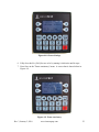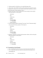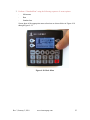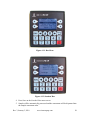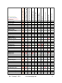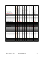
1
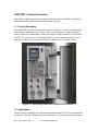
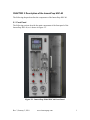
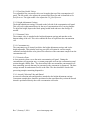
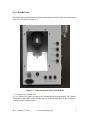
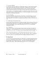
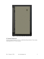
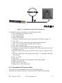
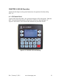
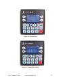
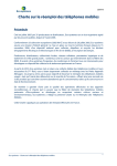
InnovaPrep® HSC-40 Hydrosol Concentrator User’s Manual The Macro to Micro Interface Table of Contents CHAPTER 1 Product Overview .................................................................................................... 1 1.1 Product Description ............................................................................................................. 1 1.2 Applications ......................................................................................................................... 1 1.3 How the InnovaPrep HSC-40 Operates................................................................................ 2 1.4 InnovaPrep History .............................................................................................................. 2 CHAPTER 2 Description of the InnovaPrep HSC-40 .................................................................... 1 2.1 Front Panel........................................................................................................................... 1 2.2 Concentration Cell Panel ..................................................................................................... 4 2.3 Left Side Panel ..................................................................................................................... 6 2.4 Back Panel ............................................................................................................................ 7 2.5 Internal Components ........................................................................................................... 8 CHAPTER 3 Installation ............................................................................................................... 9 3.1 Materials Provided............................................................................................................... 9 3.2 Materials Required But Not Provided ................................................................................. 9 3.3 Installing a Concentration Cell ........................................................................................... 10 3.4 Uninstalling a Concentration Cell ...................................................................................... 10 3.5 Filling the Extraction Fluid Reservoir ................................................................................. 10 3.6 Draining the Extraction Fluid Reservoir ............................................................................. 11 3.7 Installing the CO2 Cylinder ................................................................................................. 11 3.8 Removing the CO2 Cylinder................................................................................................ 12 3.9 Cleaning the Extraction Fluid Reservoir – 10% Bleach with Sodium Thiosulfate Deactivation .............................................................................................................................. 12 3.10 Cleaning the Extraction Fluid Reservoir – 3% Hydrogen Peroxide .................................. 14 3.11 Calibration of the Optical Sensors ................................................................................... 15 3.12 Calibration of the Pressure Transducers ......................................................................... 16 3.13 Concentration Cell Pressure Check.................................................................................. 17 CHAPTER 4 HSC-40 Operation .................................................................................................. 18 4.1 LCD Control Panel .............................................................................................................. 18 4.2 Main Screen ....................................................................................................................... 19 4.3 Setting the Extraction Fluid Volume and Consistency ....................................................... 20 4.4 Concentrating a Liquid Sample .......................................................................................... 24 4.5 Additional Sample Extractions ........................................................................................... 27 Rev 3, January 3, 2010 www.innovaprep.com i 4.6 Concentration Cell Decontamination ................................................................................ 27 4.7 Autoclaving of Concentration Cells ................................................................................... 28 4.8 Concentration Cell Storage ................................................................................................ 28 4.9 Cell Selection ..................................................................................................................... 29 CHAPTER 5 Maintenance.......................................................................................................... 33 5.1 Maintenance Schedule ...................................................................................................... 33 5.2 Tubing Replacement .......................................................................................................... 33 CHAPTER 6 CHAPTER 7 Troubleshooting .................................................................................................... 34 Revision History ..................................................................................................... 35 Rev 3, January 3, 2010 www.innovaprep.com ii CHAPTER 1 Product Overview This chapter contains a product description of the InnovaPrep Model HSC-40 hydrosol concentrator and a brief description of instrument operation. 1.1 Product Description The Model HSC-40 hydrosol concentrator, shown n Figure 1-1, quickly and efficiently concentrates waterborne bacteria, viruses, DNA, toxins, protozoa, or other particles of interest from large liquid sample volumes into liquid volumes as small as 50 microliters. The HSC-40 system uses a novel elution method to recover organisms that have been captured onto hollow fiber membrane filters membranes into very small volumes. Figure 1-1. InnovaPrep Model HSC-40 Hydrosol Concentrator 1.2 Applications The InnovaPrep technology has application anywhere that analysis of low concentrations of particles is needed. The primary area of application is for preparing and concentrating Rev 3, January 3, 2010 www.innovaprep.com 1 bacteria, viruses, DNA, and other particles of biological origin, including pathogens, for subsequent analysis by microbiological methods or with microbiological detection devices. 1.3 How the InnovaPrep HSC-40 Operates The InnovaPrep system uses a novel wet foam elution method to recover organisms that have been captured onto hollow fiber membrane filters into user settable volumes as small as 50 microliters. The wet foam is produced by releasing a surfactant solution, held under a carbon dioxide head pressure, to an ambient pressure with a timed valve. Appropriate surfactant solutions include 0.025% to 0.25% Tween 20, Triton X-100, or other surfactants or proteins. PBS, Tris, or other buffers may be added to control the solution pH. InnovaPrep can provide additional information and recommendations for extraction solution selection. 1.4 InnovaPrep History The technology was developed by a team of veteran aerosol research scientists in response to the recognized need for a macro-to-micro interface between the large liquid sample volumes collected by many bioaerosol samplers and advanced detectors which require ultra low volumes. InnovaPrep was founded in 2008 to commercialize this new concentration and sample preparation technology developed by AlburtyLab, Inc. and Page Applied Research LLC. Rev 3, January 3, 2010 www.innovaprep.com 2 CHAPTER 2 Description of the InnovaPrep HSC-40 The following chapter describes the components of the InnovaPrep HSC-40. 2.1 Front Panel The following sections describe the main components of the front panel of the InnovaPrep HSC-40, as is shown in Figure 2-1. Figure 2-1. InnovaPrep Model HSC-40 Front Panel Rev 3, January 3, 2010 www.innovaprep.com 1 2.1.1 LCD Control Panel Functions of the HSC-40 are managed through a user interface LCD control panel located in the upper left hand corner of the front panel. Detailed instructions on the operation of the LCD control panel are provided in Section 4.1 . 2.1.2 Power Switch Power to the HSC-40 is controlled by the Power on/off switch located to the right of the LCD control panel. 2.1.3 Reservoirs Two fluid reservoirs are located directly below the LCD control panel. The left hand reservoir serves as the sample Feed reservoir and the right hand reservoir serves as the Permeate reservoir. Samples to be processed may be introduced to the HSC-40 through the feed reservoir. As the sample is processed through the concentration cell, the permeate is collected in the permeate reservoir. Each reservoir is detachable for easy replacement and/or cleaning. 2.1.4 Pumps Two liquid peristaltic pumps are located directly to the right of the fluid reservoirs and below the power switch. The upper is the feed pump and the lower serves as the permeate pump. Each pump is controlled to maintain feed and permeate pressures set through the LCD control panel. 2.1.5 Control Valves Four red-faced control valves are located below the fluid reservoirs. These control the flow of the sample feed, permeate, extraction fluid and CO2. The desired position should be selected by slowly rotating the valve clock-wise. Built-in positioning detents allow the valves to snap into place, ensuring correct positioning of the valves. The position settings for each of the control valves are described below. The Feed valve has three positions as follows (noted side ports are located on the left hand side of the instrument): From side port In this position, the feed pump will draw fluid from the side port labeled Feed in to the concentration cell. From reservoir In this position, the feed pump will draw fluid from the onboard Feed reservoir located directly above the feed valve to the concentration cell. Drain reservoir In this position, fluid can be drained from the onboard feed reservoir manually using a syringe connected to the side port labeled Feed reservoir drain. NOTE: The valve must not be in this position when the feed pump is running. The Permeate valve has three positions as follows: To side port In this position, the permeate pump will direct fluid from the concentration cell permeate to the side port labeled Permeate out. Rev 3, January 3, 2010 www.innovaprep.com 2 To reservoir In this position, the permeate pump will direct fluid from the concentration cell permeate to the onboard Permeate reservoir located above the permeate valve. Drain reservoir In this position, fluid can be drained from the onboard permeate reservoir manually using a syringe connected to the side port labeled Permeate reservoir drain. NOTE: The valve must not be in this position when the permeate pump is running. The Extraction fluid valve has four positions as follows: Fill Run Drain Off In this position, the extraction fluid reservoir is connected to the side port labeled Fill located above the Extraction fluid reservoir label. The reservoir can be filled through this port. Note: Vent reservoir pressure completely prior to switching valve to this position. In this position, the extraction fluid reservoir is connected to the wet foam valve and ready for extraction. In this position, the fluid can be drained from the extraction fluid reservoir to the side port labeled Drain located above Extraction fluid reservoir label. Note: Vent the extraction fluid reservoir until an extraction fluid pressure of less than 50 psi is reached. Also attach a length of tubing with the outlet in a waste container prior to switching valve to this position. In this position, the extraction fluid reservoir is disconnected from the fill, drain, and run fluidics. The CO2 valve has four positions as follows: CO2 vent Run Off Reservoir vent In this position, the CO2 supply lines are connected to the side port labeled Vent located above Extraction fluid reservoir label. Note: Switching to CO2 vent with a CO2 cylinder fully engaged will vent the entire cylinder. Follow the instructions for removing the CO2 cylinder prior to turning the valve to this position. In this position, the CO2 supply lines are connected and ready for operation. In this position, the CO2 supply lines are valved off from the system including the extraction fluid reservoir. In this position, the CO2 head pressure is vented from the extraction fluid reservoir to the side port labeled Vent located above Extraction fluid reservoir label. 2.1.6 Extraction Fluid Level Indicator The volume of fluid remaining in the extraction fluid reservoir is indicated by the Extraction fluid sight glass located to the right of the control knobs, directly below the pumps. 2.1.7 Pressure Gauges Two pressure gauges located below the control knobs display the pressure in the CO2 supply pressure cylinder and in the Extraction fluid pressure reservoir. Directly below Rev 3, January 3, 2010 www.innovaprep.com 3 the extraction fluid pressure gauge is a PSI adjustment screw. Using the Allen wrench located below the CO2 supply pressure gauge, the gas pressure in the extraction fluid reservoir can be easily adjusted. NOTE: When the pressure is increased, the operator should wait 20 minutes prior to processing a sample. This allows for the CO2 to come into equilibrium with the extraction fluid. 2.2 Concentration Cell Panel The following sections describe the main components of the concentration cell panel of the InnovaPrep HSC-40 located behind the Plexiglas door, as is shown in Figure 2-2. Figure 2-2. InnovaPrep Model HSC-40 Concentration Cell Panel Rev 3, January 3, 2010 www.innovaprep.com 4 2.2.1 Flow Rate Needle Valves Two adjustable flow rate needle valves are located at the top of the concentration cell panel. The left needle valve adjusts the external fluid flow rate and is identified as Ext. fluid flowrate. The right needle valve adjusts the CO2 flush flowrate. 2.2.2 Height Adjustment Carriage The height adjustment carriage is located on the left side of the concentration cell panel. This easy-to-use adjustment allows for the use of concentration cell of varying lengths. To adjust the height, depress the black spring loaded knob and move the carriage as needed. 2.2.3 Retentate Valve The retentate valve is attached to the height adjustment carriage and attaches to the bottom tubing of the cell. This valve controls the flow of liquid from the concentration cell. 2.2.4 Concentrate tray The concentrate tray is located just below the height adjustment carriage and is also height adjustable. This stainless steel tray provides sa location for various sample containers and tube holders to be placed for collection of the concentrate sample from the concentration cell.. 2.2.5 Protective Door A clear protective door covers the entire concentration cell panel. During the concentration cell extraction step, a vacuum pump pulls air from the concentration panel section through a HEPA filter. The door encloses the area around the concentration cell thus controlling aerosols that may be generated as the concentrate is dispensed. The door swings outward for unobstructed access to the fiber. The door should be closed while processing samples containing bioparticles. 2.2.6 Aerosol Collection Tube and Shroud An aerosol collection tube and shroud are attached to the height adjustment carriage. Concentrate sample tubes should be positioned on the concentrate tray so that the aerosol shroud is positioned directly above the concentration cell outlet. Rev 3, January 3, 2010 www.innovaprep.com 5 2.3 Left Side Panel The following sections describe the main components of the side panel of the InnovaPrep HSC-40, as is shown in Figure 2-3. Figure 2-3. InnovaPrep Model HSC-40 Side Panel 2.3.1 Liquid CO2 Cylinder Port A 9 oz. liquid CO2 cylinder is required for carbonating the extraction fluid. The cylinder is installed in the middle of the left side panel of the InnovaPrep HSC-40 by screwing in clockwise until resistance is met. Rev 3, January 3, 2010 www.innovaprep.com 6 2.3.2 Power Cord Inlet An AC power cord is provided for use with the three-prong AC input connector located at the bottom of the InnovaPrep HSC-40 side panel. Using the power cord provided, connect the AC Power Input to an approved power source. For protection against electrical shock hazards, the HSC-40 must be directly connected to an approved power source such as a 3-wire grounded receptacle. An extension cord must not be used. If the power cable becomes cracked, frayed, broken, or otherwise damaged, it must be replaced immediately with the equivalent parts. 2.3.3 Fuse Housing One fuse is used on the InnovaPrep HSC-40 instrument. This fuse housing is located below the CO2 slot and contains a 3A 250V fuse. To replace the fuse, shut down the InnovaPrep HSC-40, disconnect the instrument from the power source, and unscrew the cap. 2.3.4 Multi Stage Communications Port A multi stage communications port is located to the right of the fuse housing. This port is for protocols that require the use of multiple units linked together or for communication with other instruments. Please contact InnovaPrep (816-619-3375) for information regarding this feature. 2.3.5 Connectors There are four vertical 1/4-28 flat bottom unions located to the right of the liquid CO2 cylinder port. These are labeled as Feed in, Feed reservoir drain, Permeate out, and Permeate reservoir drain. Use of these ports was described previously in Section 2.1.5 . There are also three horizontal 1/4-28 flat bottom unions above the Extraction Fluid Reservoir label located in the bottom right corner of the side panel. These are labeled as Fill, Drain, and Vent. Use of these ports was described previously in Section 2.1.5 . 2.4 Back Panel An access panel is located on the back side of the HSC-40. Internal components must be service by a certified InnovaPrep technician. Located on the upper right hand corner of the back panel is the operating system port. This port is used to download software updates to the system. Please contact InnovaPrep (816-619-3374) for assistance. Rev 3, January 3, 2010 www.innovaprep.com 7 Figure 2-4. InnovaPrep Model HSC-40 Back Panel 2.5 Internal Components Internal components must be service by a certified InnovaPrep technician. Please contact InnovaPrep (816-619-3374) for assistance. Rev 3, January 3, 2010 www.innovaprep.com 8 CHAPTER 3 Installation Included in this chapter are the general instructions for the setup of the InnovaPrep HSC−40. Inspect each component when unpacking. If damage is observed, do not use the instrument, and contact your shipping representative immediately. Remove any protective packaging that may be present around the HSC-40 instrument. Examine the packaging material to be sure that materials that have been provided (see the list below) are removed. 3.1 Materials Provided Component InnovaPrep HSC-40 Power Cord Programming Cable Concentration Cells 9 oz. CO2 Cylinder Female Luer Lock Permeate Connectors Qty 1 1 1 2 1 2 Male Luer Lock Permeate Connectors Decon Jumper Tube 2 1 3.2 Materials Required But Not Provided In order to use the system the extraction fluid reservoir must be filled with an appropriate reagent for sample extraction. This fluid must be provided by the user. Instructions for loading the extraction fluid is included in Section 3.5 . A personal computer is required for uploading new protocols to the HSC-40 PLC. Requirements for the personal computer that will be used to upload protocols to the PLC are summarized below: Rev 3, January 3, 2010 www.innovaprep.com 9 3.3 Installing a Concentration Cell To install a concentration cell, refer to Figure 3-1 and the following procedure: 1. Hold the concentration cell with the arrow on the label pointing up. 2. Attach the upper end of the concentration cell to connector A. 3. Pass the tubing on the lower end of the concentration cell through the fluid sensor and retentate valve pinch point. 4. Attach the connector B to the concentration cell. 5. Attach the connector C to the concentration cell. 3.4 Uninstalling a Concentration Cell To uninstall a concentration cell, refer to Figure 3-1 and the following procedure: 1. Detach connectors A and B and place caps or plugs into the ports. 2. Detach connectors C and place caps or plugs into the ports. 3. Detach the tubing from the bottom port of the concentration cell and replace with a cap or plug. *Note: The concentration cell must be filled with an appropriate storage fluid and capped prior to storing. Contact InnovaPrep regarding questions about specific membrane types (816-619-3375). 3.5 Filling the Extraction Fluid Reservoir 1. If the extraction fluid pressure will remain the same it is not necessary to adjust the Extraction fluid Figure 3-1. Concentration Cell Installation pressure regulator prior to filling; however, if a lower pressure is desired begin by inserting the hex key (found under the CO2 supply pressure gauge) into the opening for the extraction fluid pressure regulator and turning several counterclockwise turns to reduce the pressure to less than the desired pressure (if resistance is met stop turning). 2. Slowly set the CO2 valve to Reservoir vent. 3. Wait for the venting gas to stop, and then set the Extraction fluid valve to Fill. 4. Load a syringe with extraction fluid and attach it to the Fill port on the left side of the HSC-40. Rev 3, January 3, 2010 www.innovaprep.com 10 5. Fill the extraction fluid reservoir with no more than 125 mL of extraction fluid. This will allow sufficient space at the top of the reservoir for the CO2. NOTE: the Extraction fluid level gauge will not register the correct volume of extraction fluid until the system has been pressurized. Use the syringe to track the volume of extraction fluid loaded. 6. Switch the Extraction fluid valve to Run. 7. Switch the CO2 valve to Off. 8. Using the hex key (found under the CO2 supply pressure gauge), slowly turn the Extraction fluid pressure regulator until the desired pressure is reached. NOTE: It may take several turns before the regulator engages, but once it does engage the pressure can increase rapidly. 9. When you are ready to pressurize the extraction fluid, switch the CO2 valve to Run. 3.6 Draining the Extraction Fluid Reservoir 1. Attach a length of tubing from the Drain and Vent ports to a waste container. 2. If there is no pressure on the extraction fluid, increase it to approximately 25 PSI using the hex key. NOTE: If there is significantly more than 25 PSI on the extraction fluid, it may need to be lowered for the fluid to drain smoothly. Turn down the Extraction fluid pressure regulator several turns, and then slowly bleed some CO2 out of the extraction fluid reservoir by switching the CO2 valve to Reservoir vent. Note: once the pressure is reduced the Extraction fluid pressure gauge will not register the true pressure until the CO2 valve is returned to Run. 3. Switch the CO2 valve to Off. 4. Slowly switch the Extraction fluid valve to Drain. Control the flow rate using the Extraction fluid valve. 5. When the extraction fluid has finished draining, switch the Extraction fluid valve to Off. 6. Vent the Tank until it is empty by setting the CO2 knob to Reservoir vent. 3.7 Installing the CO2 Cylinder 1. Unscrew the Extraction fluid pressure regulator several turns to ensure it is set to 0 PSI. NOTE: If there is still pressure on the extraction fluid, the Extraction fluid pressure gauge will not change when you lower the regulator setting. This is okay; just make sure the pressure does not climb significantly when you are installing the cylinder. 2. Set the Extraction fluid valve to Run. 3. Set the CO2 valve to Off. Rev 3, January 3, 2010 www.innovaprep.com 11 4. Screw in the CO2 cylinder. As soon as you feel resistance, you will likely hear the CO2 gas flowing into the system and the CO2 supply pressure gauge will climb to between 800 and 1000 PSI (if the tank is full). Watch the Extraction fluid pressure gauge carefully as you screw in the cylinder; if the pressure rises above 100 PSI (or if there is already pressure on the system, the pressure increases significantly) unscrew the tank quickly and make sure the Extraction fluid pressure regulator is turned all the way down. 5. Once the system pressure has equalized, screw the CO2 tank in an additional ⅛to ¼ turn. 6. Slowly screw in the Extraction fluid pressure regulator until the desired pressure is reached. NOTE: It may take several turns before the regulator engages, but once it does engage the pressure will increase rapidly. 7. When you are ready to pressurize the extraction fluid, switch the CO2 valve to Run. 3.8 Removing the CO2 Cylinder 1. Set the Extraction fluid valve to Run. 2. Set the CO2 valve to Run. 3. Unscrew the CO2 cylinder ¼ to ½ turn (enough to disengage the pin valve, but not enough to break the o-ring seal). 4. Slowly turn the CO2 valve to CO2 vent. When CO2 starts to flow, the CO2 supply pressure gauge should show the pressure dropping. If the pressure is not dropping, unscrew the CO2 cylinder further until the pin valve fully disengages. 5. Once the CO2 supply pressure reaches zero, the CO2 cylinder can be removed. 3.9 Cleaning the Extraction Fluid Reservoir – 10% Bleach with Sodium Thiosulfate Deactivation Before or after long term storage or in the event that the HSC-40 fluidics become contaminated, it may be necessary to clean the extraction fluid reservoir and fluidics. In general it is not necessary to clean or decontaminate the extraction fluid reservoir and fluidics, providing that good, clean laboratory procedures are used. In event that cleaning of the extraction fluid reservoir is required, a cleaning procedure is provided below and an alternate procedure is provided in Section 3.10. The procedure outlined below uses a three step approach where (A) the reservoir is cleaned using 10% bleach solution, (B) the bleach is deactivated using 1% sodium thiosulfate solution, and (C) the reservoir is rinsed using sterile filtered laboratory water. It is important to follow this procedure closely to ensure that all fluidics components are cleaned. 1. Drain Reservoir - Follow procedures contained in Section 3.6 “Draining the Extraction Fluid Reservoir” to remove any remain extraction fluid. Rev 3, January 3, 2010 www.innovaprep.com 12 2. Clean with 10% bleach (Refer to Figure 3-1 for the location of the lettered points contained in these procedures.): a. Run a flexible line from the Drain and Vent ports to a waste container (this should have already been performed when draining the extraction fluid reservoir). b. Slowly set the CO2 valve to Reservoir vent. c. Wait for the venting gas to stop, and then set the Extraction fluid valve to Fill. d. Remove line “B” from the concentration cell and attach a section of tubing from line “B” to a waste container. e. Attach a section of tubing to the Fill port and attach to the outlet of a small external pump (a syringe may also be used). f. Place the inlet tube of the external pump into a 500 ml vial filled with 300 ml of 10% bleach (a syringe may also be used). g. Turn the HSC-40 on and navigate to the settings menu and select Run/Standard Run/Settings/Foam Consistency; but, do not hit start. h. Run external pump or use the syringe until fluid (10% bleach) flows out of the Drain and Vent ports. i. Press the start button on the HSC-40 control panel and continue filling until fluid starts to drip out of line B after about 10 seconds hit the stop button on the control panel, then stop the external pump. j. Let the 10% bleach solution remain in the extraction fluid reservoir for 10 minutes. k. Follow procedures contained in Section 3.6 “Draining the Extraction Fluid Reservoir” to remove the 10% bleach. 3. Deactivate the 10% bleach with 1% sodium thiosulfate: a. Slowly set the CO2 valve to Reservoir vent. b. Wait for the venting gas to stop, then set the Extraction fluid valve to Fill. c. Place the inlet tube of the external pump into a 500 ml vial filled with 300 ml of 1% sodium thiosulfate (a syringe may also be used). d. Turn the HSC-40 on and navigate to the settings menu and select Run/Standard Run/Settings/Foam Consistency; but, do not hit start. e. Run external pump or use the syringe until fluid (1% sodium thiosulfate) flows out of the Drain and Vent ports. f. Press the start button on the HSC-40 control panel and continue filling until fluid starts to drip out of line B after about 10 seconds hit the stop button on the control panel, then stop the external pump. g. Let the 1% sodium thiosulfate solution remain in the extraction fluid reservoir for 1 minute. h. Follow the procedures contained in Section 3.6 “Draining the Extraction Fluid Reservoir” to remove the 1% sodium thiosulfate. 4. Rinse with sterile filtered laboratory water: a. Slowly set the CO2 valve to Reservoir vent. b. Wait for the venting gas to stop, and then set the Extraction fluid valve to Fill. Rev 3, January 3, 2010 www.innovaprep.com 13 c. d. e. f. g. h. Place the inlet tube of the external pump into a 500 ml vial filled with 300 ml of sterile filtered laboratory water (a syringe may also be used). Turn the HSC-40 on and navigate to the settings menu and select Run/Standard Run/Settings/Foam Consistency; but, do not hit start. Run external pump or use the syringe until fluid (sterile filtered laboratory water) flows out of the Drain and Vent ports. Press the start button on the HSC-40 control panel and continue filling until fluid starts to drip out of line B after about 10 seconds hit the stop button on the control panel, then stop the external pump. Follow procedures contained in Section 3.6 “Draining the Extraction Fluid Reservoir” to remove the sterile filtered laboratory water. Chlorine test strips may be used to ensure that the bleach solution has been completely removed. 3.10 Cleaning the Extraction Fluid Reservoir – 3% Hydrogen Peroxide Before or after long term storage or in the event that the HSC-40 fluidics become contaminated it may be necessary to clean the extraction fluid reservoir and fluidics. In general it is not necessary to clean or decontaminate the extraction fluid reservoir and fluidics, providing that good, clean laboratory procedures are used. In event that cleaning of the extraction fluid reservoir is required a cleaning procedure is provided below and an alternate procedure is provided in Section 3.9. The procedure outlined below uses a two step approach where (A) the reservoir is cleaned using 3% hydrogen peroxide, and (B) the reservoir is rinsed using sterile filtered laboratory water. It is important to follow this procedure closely to ensure that all fluidics components are cleaned. 1. Drain Reservoir - Follow the procedures contained in Section 3.6 “Draining the Extraction Fluid Reservoir” to remove any remain extraction fluid. 2. Clean with 3% hydrogen peroxide (Refer to Figure 3-1 for the location of the lettered points contained in these procedures.): a. Run a flexible line from the Drain and Vent ports to a waste container (this should have already been performed when draining the extraction fluid reservoir). b. Slowly set the CO2 valve to Reservoir vent. c. Wait for the venting gas to stop, and then set the Extraction fluid valve to Fill. d. Remove line “B” from the concentration cell and attach a section of tubing from line “B” to a waste container. e. Attach a section of tubing to the Fill port and attach to the outlet of a small external pump (a syringe may also be used). f. Place the inlet tube of the external pump into a 500 ml vial filled with 300 ml of 3% hydrogen peroxide (a syringe may also be used). g. Turn the HSC-40 on and navigate to the settings menu and select Run/Standard Run/Settings/Foam Consistency; but, do not hit start. Rev 3, January 3, 2010 www.innovaprep.com 14 h. Run external pump or use the syringe until fluid (3% hydrogen peroxide) flows out of the Drain and Vent ports. i. Press the start button on the HSC-40 control panel and continue filling until fluid starts to drip out of line B after about 10 seconds hit the stop button on the control panel, then stop the external pump. j. Let the 3% hydrogen peroxide solution remain in the extraction fluid reservoir for 30 minutes. k. Follow the procedures contained in Section 3.6 “Draining the Extraction Fluid Reservoir” to remove the 3% hydrogen peroxide. 3. Rinse with sterile filtered laboratory water a. Slowly set the CO2 valve to Reservoir vent. b. Wait for the venting gas to stop, and then set the Extraction fluid valve to Fill. c. Place the inlet tube of the external pump into a 500 ml vial filled with 300 ml of sterile filtered laboratory water (a syringe may also be used). d. Turn the HSC-40 on and navigate to the settings menu and select Run/Standard Run/Settings/Foam Consistency; but, do not hit start. e. Run external pump or use the syringe until fluid (sterile filtered laboratory water) flows out of the Drain and Vent ports. f. Press the start button on the HSC-40 control panel and continue filling until fluid starts to drip out of line B after about 10 seconds hit the stop button on the control panel, then stop the external pump. g. Follow the procedures contained in Section 3.6 “Draining the Extraction Fluid Reservoir” to remove the sterile filtered laboratory water. h. Hydrogen peroxide test strips must then be used to ensure that the hydrogen peroxide solution has been completely removed. i. Repeat the rinse step until the hydrogen peroxide concentration is below the acceptable level. 3.11 Calibration of the Optical Sensors Warning: Before calibrating the optical sensors the InnovaPrep HSC-40 fluid systems must be clean and completely dry. Any residual liquid or bubbles in the tubing could interfere with accurate calibration of the optical sensors. The following procedure should be used to calibrate the optical sensors: 1. Press “maintenance” on the home screen. 2. Press “system settings”. 3. Press “Sensor Cal”. 4. Press “Enter” Rev 3, January 3, 2010 www.innovaprep.com 15 Figure 3-10. Sensor Calibration Screen After the calibration is complete a pass/fail page will appear with four light bulbs which corresponds to the four optical sensors. An illuminated light bulb indicates an optical sensor did not calibrate correctly. In most situations, sensor #3 will fail calibration because it is not plugged into the external port. If you are not using the external fluid sensor, then disregard the sensor #3 fail state and continue. 3.12 Calibration of the Pressure Transducers In order to calibrate the pressure transducers, the following items are required: ⋅ Pressure gauge with a minimum10 psi reading capability. ⋅ 60 ml syringe ⋅ Three pieces of tubing that fit ¼-28 fittings (4 in, 2 in, and 10 in pieces) ⋅ Barbed ubing “T” Assemble the above items as indicated in shown below in Figure 3-2. Rev 3, January 3, 2010 www.innovaprep.com 16 Figure 3-2. Calibration of the Pressure Transducers To calibrate the pressure transducers, use the following procedure: 1. Press “maintenance” on the home screen. 2. Press “system settings”. 3. Press “transducer zero”. 4. Follow screen prompts. 5. Disconnect A and B connectors on the concentration cell (Refer to Figure 3-1). 6. Press “next”. 7. Press “zero reset” this will reset the zero on the pressure transducers. 8. Press “verify” to make sure the transducers where zeroed. 9. Press “pass” if setting is 0.00. 10. Press “Fail” if setting is other then 0.00 and repeat steps 7-9. 11. At this point you may continue by setting the 10PSI. This step does not need to be performed every time. 12. Re-connect ports A and B to the cell. NOTE: if the cell is new, it must be wetted first. 13. To set the 10 PSI connect the syringe, pressure gauge, “T”, and attach to the right feed connector. 14. Press “set 10 PSI”. 15. Press “next”. 16. Apply 10 PSI of pressure by pressing down on the syringe plunger. 17. Hold it steady at 10 PSI. 18. Press “next” to set at 10 PSI. 19. Repeat steps 13-18 for the permeate. 3.13 Concentration Cell Pressure Check To pressure check the concentration cell, use the following procedure: Instructions not available at this time. Instructions will be with the software update. Rev 3, January 3, 2010 www.innovaprep.com 17 CHAPTER 4 HSC-40 Operation Included in this chapter are the general instructions for operation of the InnovaPrep HSC−40. 4.1 LCD Control Panel Control of the InnovaPrep HSC−40 is performed using the LCD control panel. When the HSC−40 is turned on the controller will perform a self test as shown in Figure 4-1. Figure 4-2 shows the LCD screen after the controller has passed the self-test. Figure 4-1. Controller Self-test Running Rev 3, January 3, 2010 www.innovaprep.com 18 Figure 4-2. Controller Self-test Passed 4.2 Main Screen On the main screen are the InnovaPrep HSC-40 Logo, the Run, and the Maintenance options. From the home screen, shown in Figure 4-3 the user may select the Maintenance or Run menus with the selection buttons to the left or right of the menu item. Figure 4-3. Selection of the Run menu from the Home Screen Rev 3, January 3, 2010 www.innovaprep.com 19 4.3 Setting the Extraction Fluid Volume and Consistency Prior to performing sample concentration runs the extraction fluid volume and consistency must be set. The procedure for setting these is outlined below. 1. Set the CO2 valve to “Off” 2. Set the extraction fluid pressure to desired level by removing the hex key from below the CO2 supply pressure gauge, inserting the hex key into the regulator opening just below the Extraction fluid pressure gauge, and turning it slowly until the desired pressure is attained. 3. Set the CO2 valve to “Run”. 4. Wait a minimum of 10 minutes for the CO2 to dissolve into the extraction fluid. 5. Enter the "Foam consistency" menu using the following sequence of menu options: ⋅ Main menu ⋅ Run ⋅ Standard run ⋅ Settings ⋅ Extract settings ⋅ Foam consistency Screen shots of the appropriate menu selections are shown below in Figure 4-4throughFigure 4-8. Rev 3, January 3, 2010 www.innovaprep.com 20 Figure 4-4. Main Menu Figure 4-5. Run Menu Rev 3, January 3, 2010 www.innovaprep.com 21 Figure 4-6. Standard Run Figure 4-7. Standard Run Settings Rev 3, January 3, 2010 www.innovaprep.com 22 Figure 4-8. Extract Settings 6. Fully close the Ext. fluid flowrate valve by turning it clockwise until it stops. 7. Press Start on the "Foam consistency" menu. A screen shot is shown below in Figure 4-9. Figure 4-9. Foam consistency Rev 3, January 3, 2010 www.innovaprep.com 23 8. Slowly open the Ext. fluid flowrate valve until fluid starts to flow. 9. Allow at least 5 mL of fluid to drain out of the retentate port to purge the system. 10. Adjust the Ext. fluid flowrate valve until the desired foam consistency is reached. 11. Press Stop on the "Foam consistency" menu. 12. Set the “Foam timer” value in seconds in the "Extract settings" menu using the following sequence of menu options: ⋅ Main menu ⋅ Run ⋅ Standard run ⋅ Settings ⋅ Extract settings Foam timer ⋅ Foam consistency 13. Test the extraction volume by pressing “Test extract” in the "Extraction settings" menu using the following sequence of menu options: ⋅ Main menu ⋅ Run ⋅ Standard run ⋅ Settings ⋅ Extract settings Test extract 14. Adjust the “Foam timer” until the desired extraction volume is achieved using the following sequence of menu options: ⋅ Main menu ⋅ Run ⋅ Standard run ⋅ Settings ⋅ Extract settings Foam timer 4.4 Concentrating a Liquid Sample 1. Place a feed sample into the Feed reservoir on the front panel of the HSC-40. 2. Place a sample concentrate tube under the retentate tube on the bottom of the concentration cell. Rev 3, January 3, 2010 www.innovaprep.com 24 3. Perform a "Standard Run" using the following sequence of menu options: ⋅ Main menu ⋅ Run ⋅ Standard run Screen shots of the appropriate menu selections are shown below in Figure 4-10 through Figure 4-12. Figure 4-10. Main Menu Rev 3, January 3, 2010 www.innovaprep.com 25 Figure 4-11. Run Menu Figure 4-12. Standard Run 4. Press Start on the Standard Run menu screen. 5. Sample will be automatically processed and the concentrate will be dispensed into the sample concentrate tube. Rev 3, January 3, 2010 www.innovaprep.com 26 4.5 Additional Sample Extractions Additional extractions of the concentration cell can be performed by pressing Extract Again. 4.6 Concentration Cell Decontamination Decontamination of the concentration cell may be necessary in some instances. Decontamination can be performed with any of the methods described below. ⋅ ⋅ ⋅ ⋅ Perform one or more additional extractions of the concentration cell to remove remaining material from the concentration cell Place clean feed fluid, filtered laboratory grade water, or surfactant solution into the feed reservoir and run as a sample. Follow with additional extraction as necessary. Place 200 ppm sodium hypochlorite into the feed reservoir and run as a sample. Follow with 200 ppm sodium thiosulfate to deactivate the sodium hypochlorite. Follow with sterile filtered laboratory grade water. Use chlorine test strips to ensure that the sodium hypochlorite solution has been completely removed. Place 3% hydrogen peroxide into the feed reservoir and run as a sample. Follow with multiple rinses of sterile filtered laboratory grade water. Use hydrogen peroxide test strips to ensure that the hydrogen peroxide solution has been completely removed. The following procedure was developed at InnovaPrep for decontaminating the system with 3% Hydrogen Peroxide: 1. Fill Feed Reservoir with 3% Hydrogen Peroxide until it is as full as you can get it without spilling out. There should be a mound of fluid at the top of the reservoir 2. Let stand for 5 min. 3. Place a catch cup on the shelf below the filter outlet. 4. Using a flexible tube, connect a 60 ml syringe to feed reservoir drain port. 5. Set feed knob to “Drain reservoir”. 6. Pull 50 ml of deacon fluid out of reservoir. 7. Set feed knob to “From reservoir”. 8. Turn on HSC-40. 9. Start a standard run 10. After 5 ml of fluid have been processed, simultaneously and carefully open retentate valve with the end of a standard screw driver, and pinch the permeate pump peristaltic tubing between your thumb and index finger. Allow 5 ml of the fluid to drain out into the catch cup, release tube and valve, allow run to finish. 11. When run is complete refill reservoir as noted in step 1 with filtered DI water. 12. Set feed knob to drain reservoir and pull all of the water out with syringe. Repeat this step. 13. Refill reservoir as in step 1 with filtered DI water 14. Start standard run after 1 min open retentate and pinch permeate line. Allow 20 mils to flow through fiber bore close retentate and release perm line, allow 20 Rev 3, January 3, 2010 www.innovaprep.com 27 mills to flow out perm repeat until only 5 mills remain then allow run to complete itself. Repeat this step 15. Fill feed res with 15 ml of storage fluid. 16. Run standard run after 30 sec. open retentate allow storage solution to drip out for 5 seconds the turn off unit. 4.7 Autoclaving of Concentration Cells The following autoclave method is recommended for use with hollow fiber modules: 1. Remove and discard all pouches, as these are not autoclavable; wet the membrane (optional). 2. Loosen all sanitary connections, Luer™ fittings, clamps and flange nuts to avoid damaging the module during the autoclave cycle. 3. Wrap all open ports of the connecting tubing with autoclave paper. 4. Pre-warm the module and use pre-vacuum steps if possible. 5. Slowly ramp up the temperature of the autoclave. Use a ramp time of minutes or half of the hold time of autoclave, whichever is LARGER. 6. Hold the autoclave at 121ºC for 30 minutes, do not exceed 124ºC. 7. Slowly ramp down the temperature of the autoclave to room temperature. 8. Use a ramp down time of 15 minutes or half of the hold time of autoclave, whichever is LARGER. A one minute dry cycle is acceptable, though not necessary. 9. Tighten all sanitary connections, Luer™ fittings or any other clamps or connections if they are fitted in the module. 4.8 Concentration Cell Storage Concentration cells are generally stored in 1% hydrogen peroxide or 20 ppm bleach. The cells should be rinsed with sterile filtered water prior to use and tested with chlorine or hydrogen peroxide test strips to ensure complete removal. Please contact InnovaPrep (816-619-3375) for assistance in selection of other storage fluids or with dry storage. Rev 3, January 3, 2010 www.innovaprep.com 28 4.9 Cell Selection Table 4-1 contains a chemical resistance chart for the various components of the HSC-40 system. This chemical resistance chart is intended for use as a guide, not as a guarantee of chemical compatibility. Variations in temperature, concentrations, durations of exposure, and other factors may affect the use of the product. It is recommended that testing be performed under the user’s specific conditions. Rev 3, January 3, 2010 Cellulose Ester (CE) / Mixed Cellulose Ester (ME) Regenerated Cellulose (RC) Polysulfone (PS) / Polyethersulfone (PES) Polypropylene (PP) Polyvinylidene difluoride (PVDF) Nylon (N) Stainless Steel (SS) Polyester (P) Fluorocarbon (F) R=Recommended L= Limited Exposure NR=Not Recommended U=Unknown 5% Acetic acid 25% Acetic acid Acetic acid (glacial) Acetone Acetonitrile Dilute Ammonium hydroxide Conc. Ammonium hydroxide Amyl acetate Amyl alcohol Aniline Benzene Benzyl alcohol Boric acid Brine Bromoform Butyl acetate Butyl alcohol Butyl cellosolve Butylaldehyde Carbon tetrachloride Cellosolve Chloroacetic acid Chloroform Chromic acid HSC-40 Sample Fluidics Table 4-1. Chemical Resistance Chart L NR NR NR NR U R NR NR U NR NR R U U NR NR U U NR U NR NR L L NR NR NR NR NR NR NR L NR NR NR R R NR NR L NR NR NR NR NR L NR R R R R R R L R R R R R R R R R R L R R L R R NR R R R NR NR R R NR L NR L NR R R NR NR R NR NR NR R NR L NR R R R R R R R R R R R R R R R R R U R R R R R L R R R L L R R R R R R L R R R R R R R R R R R R NR NR L R U R R L R R R U L R U R L U U NR U NR R NR L L L R U R R R R R L L L R U L R U U L U L R L L NR NR R U U U L R U R NR R R U R R U U R U U R U R R R R U R R R R R R R R R U R U U R U R R R U www.innovaprep.com 29 Rev 3, January 3, 2010 HSC-40 Sample Fluidics Cellulose Ester (CE) / Mixed Cellulose Ester (ME) Regenerated Cellulose (RC) Polysulfone (PS) / Polyethersulfone (PES) Polypropylene (PP) Polyvinylidene difluoride (PVDF) Nylon (N) Stainless Steel (SS) Polyester (P) Fluorocarbon (F) R=Recommended L= Limited Exposure NR=Not Recommended U=Unknown Cresol Cyclohexane Cyclohexanone Diacetone alcohol Dimethyl formamide Dimethylsulfoxide 1,4 Dioxane Ethers Ethyl acetate Ethyl Alcohol 15% Ethyl alcohol 95% Ethyl alcohol Ethylene dichloride Ethylene glycol Ethylene oxide 2% Formaldehyde 30% Formaldehyde 25% Formic acid 50% Formic Acid Freon® Gasoline Glycerine Glycerol Hexane Hexanol 5% Hydrochloric acid 25% Hydrochloric acid 37% Hydrochloric acid 25% Hydrofluoric acid 30% Hydrogen peroxide Iodine solutions Isobutyl alcohol Isopropanol Isopropyl acetate Isopropyl alcohol NR NR NR NR U U U NR U U U U NR NR NR L L L L NR NR NR U NR U NR NR NR NR R U U U NR NR NR L NR NR NR NR NR NR NR L R L NR L NR L L NR NR R R R R R L R NR NR NR R NR R L NR L R R R R L R L R R R R R R R L R R R R R R R R R R R NR NR L R NR R R R R NR L NR NR NR NR L NR NR R R L NR R R R R R R R L R R R R R R R L R NR R R NR R R R R R R R R L R R R R L R R R R R R R R R R R R R R L NR R R R R R R NR R L R NR L R L R R R R R R R R R R R R R R R R R R R R R R R R R R R NR R R R R U U R R R R R R R R R R NR NR NR R R R L R L NR NR L NR L NR NR L NR R R R L R U U R L R R R L L L R R L L R R R R R R NR NR NR NR L NR R L L L U U R U NR U R NR U R R R U R U R R NR NR R R R R R R R R R NR R U U R R R R R R R U U R R R R R R R R R R R R R R R R R R R R R R R R R R R R R www.innovaprep.com 30 Rev 3, January 3, 2010 HSC-40 Sample Fluidics Cellulose Ester (CE) / Mixed Cellulose Ester (ME) Regenerated Cellulose (RC) Polysulfone (PS) / Polyethersulfone (PES) Polypropylene (PP) Polyvinylidene difluoride (PVDF) Nylon (N) Stainless Steel (SS) Polyester (P) Fluorocarbon (F) R=Recommended L= Limited Exposure NR=Not Recommended U=Unknown Isopropyl ether Jet Fuel 640A Kerosene Lactic acid Methyl acetate Methyl alcohol 98% Methyl alcohol Methyl cellosolve Methyl chloride Methyl ethyl ketone Methyl formate Methylene chloride N-methyl-2-pyrrolidone Mineral spirits Monochlorobenzene 5% Nitric acid 25% Nitric acid 6 N Nitric acid 70% Nitric acid Conc. Nitric acid Nitrobenzene Nitropropane Oils, mineral Pentane 25% Perchloric acid Perchloroethylene Petroleum based oils Petroleum ether 0.5% Phenol 10% Phenol 25% Phosphoric acid 1 N Potassium hydroxide 25% Potassium hydroxide 50% Potassium hydroxide Propanol NR NR NR R NR L L NR NR NR U NR U NR U L NR NR NR NR NR U R NR NR NR NR NR NR NR NR U U U U L R R R NR L L L NR NR NR L NR R L L NR NR NR NR NR NR R R NR NR R R R NR NR L NR NR R R R R R R R R L R R L R R R R R NR NR NR NR L L R R L R R R R R L L R NR R R R R R NR L R R NR NR NR L NR R NR R R R NR R NR NR R R NR NR R R R L R NR R R R L R R R R R R R R R R R R R L R R L NR NR NR L R R NR L R R R R R R R R R R R R R R R R R L L R R R R R NR NR R NR L R R R R R R R R R R R R R R R R L R L R L L L L R U L U R U NR NR NR NR NR L U R R NR L R U NR NR L L L L NR R R R L R R R L R R U L L R U R R R R R L U R L L L R U L L NR L L L R U U L R L U U U U U U NR U U U R L R NR NR NR U U R U U R R L NR U R R L R R R R R R R R R R R U R U R U R R R R R R U R R R R R U R R R R R R R www.innovaprep.com 31 Rev 3, January 3, 2010 Cellulose Ester (CE) / Mixed Cellulose Ester (ME) Regenerated Cellulose (RC) Polysulfone (PS) / Polyethersulfone (PES) Polypropylene (PP) Polyvinylidene difluoride (PVDF) Nylon (N) Stainless Steel (SS) Polyester (P) Fluorocarbon (F) 50% Sodium hydroxide Conc. Sodium Hydroxide Sodium hypochlorite 5% Sulfuric acid 25% Sulfuric acid 6 N Sulfuric acid Conc. Sulfuric Acid Tetrahydrofuran Toluene 25% Trichloroacetic acid Trichlorobenzene Trichloroethane Trichloroethylene Triethylamine Turpentine Urea 6 N Urea Water Xylene HSC-40 Sample Fluidics R=Recommended L= Limited Exposure NR=Not Recommended U=Unknown Pyridine Silicone oil 0.1 N Sodium hydroxide 5% Sodium hydroxide 25% Sodium hydroxide NR R R R R NR R L NR NR R R R L L NR R R R R R R R R R L R R R R L R R R R R R L L L NR U R L NR R R R R R U U NR NR R L NR NR NR NR R NR NR L R NR NR R NR R NR NR NR R R L L NR R R NR R R R R R R R R R R R R R R R R NR L R NR L R NR NR R NR R NR R R L R R R NR R R R R R R L R R R R R R R R R R R L R R R R R NR R R R R R R R L NR L NR NR NR R R L U L L R L R R R R L L NR NR NR NR NR R R NR U L L R R L L R L NR NR U NR NR NR NR R U NR U L R U U R R R NR R R R R R R R R R R U R R R R R R R R U NR NR NR NR NR NR U NR NR U NR U U R NR www.innovaprep.com 32 CHAPTER 5 Maintenance 5.1 Maintenance Schedule A regular maintenance schedule should be strictly followed in order to keep the InnovaPrep HSC-40 in optimal working condition. Please adhere to the following maintenance schedule: Daily Weekly Monthly Yearly 5.2 Tubing Replacement If any of the exposed tubing on the outside of the InnovaPrep HSC-40 needs to be replaced, follow these steps: Changing pump tubing 1. 2. 3. 4. 5. 6. 7. 8. 9. Squeeze black side buttons on pump housing to open Remove old tubing by disconnecting the tubing from the connectors Lift old tubing out of pump slot Put o-ring around new tubing Even up the ends of the tubing Drape middle of tubing over the pump slot Slightly pull tubing downward to get rid of any slack Connect tubing ends to connectors Close pump housing Rev 3, January 3, 2010 www.innovaprep.com 33 CHAPTER 6 Troubleshooting Problem: During a standard run if the HSC-40 will not progress past the “Starting Up” window. Check: Permeate pressure. If it is low, it is an indication that there is a loose connection on the permeate side. Tighten both thumb screws on the permeate side. Please contact InnovaPrep for technical assistance and troubleshooting. InnovaPrep LLC 132 E. Main St. Drexel, MO 64742 Phone: 816-619-3375 [email protected] www.innovaprep.com Rev 3, January 3, 2010 www.innovaprep.com 34 CHAPTER 7 Revision History Rev 1, written for software version 1.0, July 21, 2009 Rev 2, written for software version 1.0, November 4, 2009 Rev 3, written for software version 1.0, January 3, 2010 Rev 4, written for software version 1.0, _______________ Rev 3, January 3, 2010 www.innovaprep.com 35