1
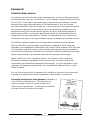
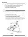
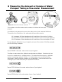
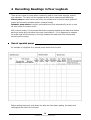
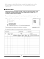
Groundwater
Monitoring for
Pump Operators
TOOLKIT for WATER SERVICES: Number 6.1
This document is a guideline for pump operators who need to monitor groundwater.
The document is primarily intended for Water Services Providers and their staff.
Groundwater Monitoring for Pump Operators
© DWAF, March 2004
Published by
Department of Water Affairs and Forestry
Directorate: Information Programmes
Private Bag X313
PRETORIA 0001
Republic of South Africa
Tel: (012) 336 7500
This publication may be reproduced only for non-commercial purposes and only after appropriate
authorisation by the Department of Water Affairs and Forestry has been provided. No part of this
publication may be reproduced in any manner without full acknowledgement of the source.
Implemented by
CSIR
Written by
Phillip Ravenscroft and Ricky Murray
Editing
Anthea Josias
Artwork
Vusi Malindi
Layout and design
Gill McDowell
Inputs
Eddy van Wyk
Produced under:
The NORAD-Assisted Programme for the Sustainable Development of Groundwater Sources
under the Community Water and Sanitation Programme in South Africa
Foreword
Toolkit for Water Services
Groundwater has historically been given limited attention, and has not been perceived as
an important water resource, in South Africa. This is reflected in general statistics showing
that only 13 % of the nation’s total water supply originate from groundwater. However,
because of the highly distributed nature of the water demand in rural and informal
peri-urban settlements, regional schemes are, in most instances, not economically feasible.
And because of generally increasing water scarcity and decreasing available river and
spring flows during low flow and drought periods, as well as wide-spread problems of
surface water pollution in rural areas, groundwater will be the most feasible option for
a large part of the new water demand. Already it is estimated that over sixty percent of
community water supply is from groundwater, making it a strategically important resource.
The NORAD-Assisted Programme for the Sustainable Development of Groundwater
Sources under the Community Water and Sanitation Programme in South Africa was
managed by the Department of Water Affairs and Forestry (DWAF) between 2000 and 2004.
The Programme undertook a series of inter-related projects aimed at enhancing capacity
of water services authorities and DWAF to promote and implement sustainable rural water
supply schemes based on groundwater resources and appropriate technologies.
Page 2 has a full list of the Programme outputs. The formats for these range from
documents to software programmes and an internet portal, to reference sites where
communities have implemented appropriate technologies. For more information on the
“package” of Programme outputs contact your nearest DWAF Regional Office or Head
Office in Pretoria.
It is our sincere hope that this Programme will contribute to the body of work that exists
to enable more appropriate use and management of groundwater in South Africa.
Grounwater Monitoring for Pump Operators is Number 6.1
in the Toolkit for Water Services. This document is a
reference manual primarily for pump operators who
need to monitor groundwater. The document is intended
for Water Services Providers and their staff.
1
Groundwater Monitoring for Pump Operators
Toolkit for Water Services
1
1.1
1.2
Overview documentation
A Framework for Groundwater Management of Community Water Supply
Implementing a Rural Groundwater Management System: a step-by-step guide
2
2.1
Descriptors
Standard Descriptors for Geosites
3
3.1
3.2
3.3
3.4
3.4.1
3.4.2
3.4.3
3.4.4
3.4.5
3.4.6
3.4.7
Groundwater Protection
Involving community members in a hydrocensus
Guidelines for protecting springs
Guidelines for protecting boreholes and wells
Guidelines on protecting groundwater from contamination
Animal kraals, watering points and dipping tanks
Burial sites
Informal vehicle servicing, spray painting and parts washing facilities
Pit latrines
Runoff water
Subsistence agriculture
Informal waste disposal
4
4.1
Maps
Thematic Groundwater Maps
5
5.1
5.1.1
5.1.2
5.1.3
5.1.4
5.2
5.2.1
5.3
5.3.1
Software
Sustainability Indexing Tool (SusIT)
SusIT User Guide
SusIT Field Data Capturer’s User Manual
SusIT Questionnaire
SusIT Information Brochure
AquiMon Management System
AquiMon Information Brochure
Geohydrological Data Access System (GDAS)
GDAS Information Brochure
6
Monitoring
6.1
Groundwater Monitoring for Pump Operators
7
7.1
7.2
7.3
Sustainability
Sustainability Best Practices Guidelines for Rural Water Services
Introductory Guide to Appropriate Solutions for Water and Sanitation
Decision Making Framework for Municipalities
8
8.1
8.2
8.3
Reference Sites
Genadendal Information Brochure
Kammiesberg Information Brochure
Maputaland Information Brochure
2
Groundwater Monitoring for Pump Operators
Table of Contents
Foreword
2
Toolkit for Water Services
3
Acronyms
4
1 Groundwater Monitoring
What is groundwater and why do we monitor it?
The role of the pump operator in monitoring groundwater
5
5
6
2 Measuring Water Levels
Introduction
Equipment required for measuring the water level
Step by step – measuring the water level
Cleanliness
Safety
7
7
7
9
12
12
3 Measuring the Amount or Volume of Water Pumped: Taking a Flow-meter
Measurement
13
4 Recording Readings in Your Logbook
Manual operated pumps
Automatic pumps
General – for both manual and automatic pumps
14
14
15
16
5 The Borehole
Commonly used pumps
Switches used on automatic pumps
17
17
19
6 Sample Evaluation Form for Pump Attendants – Groundwater Monitoring
22
7 References and additional reading
23
8 Glossary and definitions
24
Acronyms
CMA
Catchment Management Agency
CWSS
Community Water Supply and Sanitation
DWAF
Department of Water Affairs and Forestry
O&M
Operation and Maintenance
SSA
Support Services Agent
WRM
Water Resource Management
WSA
Water Services Authority
WSDP
Water Services Development Plan
WSP
Water Services Provider
4
Groundwater Monitoring for Pump Operators
1 Groundwater Monitoring
What is groundwater and why do we monitor it?
Groundwater is water that is found below the surface of the earth in the small cracks
and spaces found in the rocks and sand underground. Groundwater originally comes
from rain that has soaked into the ground over large areas, and is stored underground like
a large sponge filled with water. Naturally, springs are found where this underground water
overflows onto the surface of the earth. Boreholes are holes drilled deep into the rock
formations below the earth’s surface. By using a pump installed inside a borehole, water
can be pumped from this underground sponge for people to use.
We monitor groundwater by recording how much water we have used and by recording
the level of the water under the ground. The purpose of monitoring groundwater is to
be able to know how much water is available for use and if it is suitable for drinking.
When we pump water from a borehole, the water level underground drops, as shown
in the illustration.
Diagram 1: Groundwater levels before and during pumping
Before pumping
spring
borehole
rest water level
During pumping
borehole
water level during
pumping
5
Groundwater Monitoring for Pump Operators
The role of the pump operator in monitoring groundwater
1 The pump operator is a vital link in the groundwater monitoring chain. The pump
operator records the level of the water in the borehole and the amount of water that has
been pumped. The pump operator also notes any problems or changes that they may
have noticed with the borehole and the pump.
2 This information is sent to the Water Services Authority (WSA) where it is entered into
the computer groundwater management system.
3 Reports from this system are supplied to the WSA technical staff, who analyse the data.
From this analysis, they will see if the borehole is being over-pumped or under-pumped
and may make recommendations to the pump operator to change the way that the
borehole is being operated. The WSA technical staff may also ask a specialist
groundwater expert for advice on some of the information.
4 The information collected by the WSA is used for reporting to DWAF Hydrological
Services. They are responsible for looking after all the groundwater in South Africa.
If the pump operator does not keep good records, all these other people (the WSA, DWAF,
etc.) are unable to do their jobs in managing groundwater. This guideline document focuses
on what is needed for the pump operator to keep good records.
Diagram 2: The groundwater monitoring feedback cycle
1
log sheet
2
pump operator
3
4
technical
supervisor
DWAF
technical manager
6
Groundwater Monitoring for Pump Operators
2 Measuring Water Levels
Introduction
The organisation that operates the water scheme on a day-to-day basis is called the Water
Services Provider (WSP). As part of their activities of Operation and Maintenance (O&M),
the WSP must ensure that regular measurements are made of the water levels in the
boreholes as well as the abstraction from the borehole, and that these measurements are
accurately recorded in the borehole logbook. The WSP must also make sure that these
records are passed on to the Water Services Authority (WSA). The WSA is usually the
District Municipality for the area.
Normally, the pump operator or technical operator is responsible for measuring and
recording the water levels and water meter readings as well as hour meter readings
on electrical pumps.
Equipment required for measuring the water level
The following equipment is required to measure water
levels:
Piezometer tube
Dip meter
Ruler
Logbook
The piezometer tube is a small diameter pipe
that goes down into the borehole. The water
level is measured by lowering the dip meter
cable into the piezometer tube. When not
being used, the top of the piezometer tube
should be closed with an end cap.
water level
pipes
piezometer
tube
borehole
pump
piezometer
tube
Diagram 3: The piezometer tube
Diagram 4: When not in use, the piezometer tube is
closed with an end cap
7
Groundwater Monitoring for Pump Operators
We use a dip meter to measure water levels.
A dip meter consists of a length of electrical
cable rolled onto a spindle, with a weight
(also called a probe) on the end of it. It looks
like an electric extension cable (but it is not
and cannot be used as an extension cable).
The dip meter probe measures the water level
in the borehole when it touches the water.
Diagram 5: The dip meter
All dip meters have a way of showing when the weight
or probe has reached the water. In most cases, Diagram 6: The dip
meter probe
this is shown by a gauge, but some dip meters
use a light or buzzer to tell one when the weight
is in the water. Some dip meters also have an
on / off switch.
dip meter gauge
switch
gauge
probe
light
dip meter with
tape measure cable
Diagram 7: Examples of different types of dip meters
The dip meter works in the following way:
When it is switched on, a small electric current becomes active in the cable.
When the probe is under water, the current flows in the cable and the gauge
moves as it records the current.
When the probe is lifted out of the water, the current stops flowing and the gauge
returns to its original zero position.
Therefore, if you lower the probe into the borehole and watch for when the gauge moves,
you can measure the depth to the water level in the borehole.
You can try this using a bucket of water. Place the probe into a bucket of water and
watch the gauge as the probe touches the water. This is also a good way of checking
if your dip meter works.
8
Groundwater Monitoring for Pump Operators
Step by step - measuring the water level
Always take your measurements at the same place. Normally this is the top of the
piezometer tube. Measure how far the piezometer tube sticks up above the base plate
of the discharge head, and record this measurement in your logbook. This measurement
is referred to as the datum height or reference level. If the pump is lifted out of the borehole
or the piezometer tube moves for any other reason, measure it again and record the value
in your logbook in the comments column.
Here are the steps to measuring the water level:
1. Make sure that you have the following:
Pen
Logbook
Dip meter
A 1 metre ruler or tape measure
2. Wash your hands before you use the dip meter.
3. Switch the dip meter on, if it has an on / off switch.
4. Remove the end cap from the top of the piezometer tube.
5. Slowly lower the probe into the piezometer tube until the gauge moves.
Diagram 8: Gauge showing that the probe is not in
the water
Diagram 9: Gauge showing probe is in the water
9
Groundwater Monitoring for Pump Operators
6. Lift and lower the probe a little, checking the
gauge movement, to make sure you have the
correct water level.
dip meter cable
7. Keep your finger on the correct point
on the cable.
Diagram 10: Keep your finger on the cable
piezometer tube
8. Pull the cable out of the piezometer tube
until a metre mark is visible.
14m mark on the
dip meter cable
Diagram 11: Pull the cable out of the piezometer tube
9. Measure from the metre mark on the cable
to your finger with the ruler – this will give
you the centimetres.
metre ruler
Diagram 12: Measure the centimetres from
the cable metre mark to your
your finger
10
Groundwater Monitoring for Pump Operators
10. Record the metres and centimetres
in your logbook.
Diagram 13: Record the measurement in
your logbook
11. Check the measurement and that you have recorded it correctly.
In this diagram, the measurement
is 14 metres and 7 centimetres
or 14.07 metres.
Don’t forget to add the zero before
the seven when the centimetre
reading is less than 10 centimetres.
Record the reading in the logbook
as 14m07cm.
Diagram 14: This measurement is 14 metres and 7 centimetres
(14.07m)
This reading is 14 metres and 70 centimetres
or 14.70 metres. Record the reading
in the logbook as 14m70cm.
Diagram 15: This measurement is 14 metres and 70 centimetres
(14.70m)
11
Groundwater Monitoring for Pump Operators
Cleanliness
Remember that you are working with the drinking water supply of the community:
Always make sure that your hands and your equipment are clean.
Your dip meter must be stored in a place that is clean and out of the reach
of children.
It is best to store measuring equipment in a clean plastic bag.
Wash the cable of your dip meter, if it is dirty.
Safety
Operating moving machinery like a motorised pump is dangerous, and can cause serious
injury if the correct safety procedures are not strictly followed at all times.
When measuring water levels on a pump that has belts, the piezometer tube should
be well clear of the belts. If the piezometer tube is close to the belts, switch the
motor off before taking the water level reading.
Avoid wearing loose clothing that could get caught in the belts.
If the belts are driven from an electric motor with an automatic switch, always
switch the electricity off before taking a water level reading.
With electric systems there are additional safety precautions to be taken, to avoid
electric shock. Never touch any electrical component unless authorised to do so,
and having followed the correct safety measures. Immediately clear standing water
out of the pump house and ensure that water cannot enter the pump house.
Diagram 16: Avoid wearing loose clothing that could get caught
in the belts
12
Groundwater Monitoring for Pump Operators
3 Measuring the Amount or Volume of Water
Pumped: Taking a Flow-meter Measurement
Diagram 17: Water meter and water meter dial
The numbers on the flow-meter are the number of kilolitres that have been
pumped.
One kilolitre is the same as 1m3 (one cubic metre), which is the same as 1000 litres.
The smaller clock-like dials on the water meter show smaller amounts.
X 0.1 measures 100 litre intervals and a full revolution of the clock is 1 kilolitre.
X 0.01 measures 10 litre intervals and a full revolution of the clock equals 100 litres.
X 0.001 measures 1 litre intervals and a full revolution of the clock equals 10 litres.
For recording the abstraction in your logbook, just record the number of kilolitres pumped,
as in the following examples:
Record 26458 in the water meter column of your logbook.
The dials of water meters from different manufacturers are different. Sometimes the last
one or two numbers are in a different colour. This means that the number in a different
colour is measuring a part of a kilolitre. On these meters, only record the kilolitres
(the figures in black and white numbers, on our examples). If you are not sure of the
readings on your water meter, ask your supervisor for advice.
Record 7223 kilolitres in the water meter column of your logbook.
Record 950 kilolitres in the water meter column of your logbook.
13
Groundwater Monitoring for Pump Operators
4 Recording Readings in Your Logbook
There are two types of pump motors commonly used for rural water supplies, manual
and automatic. For each one, the operator would record measurements differently.
Manual pumps are switched on and off by the operator and include all diesel powered
pumps and manually operated electric powered pumps.
Automatic pump motors are electric powered pumps, that automatically switch on and
off with a timer or another switch.
With manual pumps, it is recommended that the operator measures the water level before
starting to pump and just before the pump is switched off. If it is dangerous to measure
the water level while the pump is running, measure the water level five minutes after
switching off the pump.
Manual operated pumps
An example of a logbook for a manual pump would look like this:
Before starting the pump, write down the date, the flow-meter reading, the water level
reading and the time in the columns.
14
Groundwater Monitoring for Pump Operators
When the pump is switched off, write down the water level reading, the time and the
flow-meter reading. It is best to take the water level reading just before the pump
is switched off.
Automatic pumps
With automatic pumps, the operator must take a water level reading each time the pump
is inspected. This should be done once a week if possible, but will normally have to fit
in with the scheduled visits of the operator.
For example, if an operator is responsible for ten boreholes and visits each one routinely
every two weeks, then they will measure and record water levels every two weeks.
With an automatic pump the following must be recorded:
Date
Time of reading
Water level
Water meter reading
Hour-meter reading
Whether the pump is on or off at the time of measurement
The hour-meter can be found on the electrical control box.
An example of a logbook for an automatic pump would look like this:
15
Groundwater Monitoring for Pump Operators
Diagram 18: Hour meter
General information for both manual and automatic pumps
The logbook must be kept in a protective plastic bag in a safe place, either in or near the
pump house.
The logbook should be a carbon paper duplicate book. Every two months the top copy
of your log sheets must be torn out and sent to the Water Services Authority (WSA).
Your logbook has a duplicate copy for each page. This is to ensure that both the operator
and the WSA can have a record of the readings taken at the borehole.
It is important to record any other information about the borehole in the logbook.
This would include:
If a water sample was taken.
Manual measurements of the flow (that is, measuring the pumping rate using
a bucket and a stopwatch).
Any leaks at the pump head.
If a water meter is not working.
If the pump or motor is not working properly.
If the pump is pumping much less water than normal (this is important information
for the WSP).
Any work that has been done on the pump or the motor, either by the pump
operator or by someone from outside.
Service information, including the details of oil changes and filter replacement.
Resetting of timer switches.
Replacement of any components.
Major works like removing or replacing the pump.
If someone from DWAF or from the Municipality visits the borehole without the
pump operator, they must also fill in the logbook.
If the non return valve is not working properly. When it is not working the water
flows backwards after the pump is switched off, and the water meter will run
backwards for a short time after stopping the pump.
16
Groundwater Monitoring for Pump Operators
5 The Borehole
Commonly used pumps
There are two types of pumps commonly used for community water supply:
the rotary or positive displacement pump and the centrifugal or submersible pump.
1 The Rotary or Positive Displacement Pump
(also called a progressive cavity or rotor / stator pump)
The motor sits above the ground in the pump house.
The pump is driven with belts and can have a diesel
or electric motor.
Common brands used in South Africa are Mono
and Orbit pumps.
The pump consists of three parts:
The discharge head
The rising main of galvanized steel
The pump element.
rubber cap
discharge
head
rising
main
It is important that this type of pump is never
pumped against a closed valve, as this will
damage the pump. Always make sure that all
valves are opened before starting the pump.
If your pump has a pump to waste or scour valve
in the pump house, start the pump with this open
and slowly close the valve once the pump
is running and the water is flowing.
stabiliser
borehole
casing
water
level
shaft
pump
element
Diagram 19: The rotary or positive diplacement pump
strainer
17
Groundwater Monitoring for Pump Operators
2 The Centrifugal or Submersible Pump
The pump motor is powered by electricity and is located at the pump, inside the borehole.
For small pumps a rising main of black plastic polyethylene (HDPe) pipe is used.
On larger pumps, a steel galvanized pipe is used for the rising main. Special types of
lay-flat or “fireman’s hose” like Well Master can also be used.
These pumps can sometimes be damaged by lightning strikes.
Diagram 20: Centrifugal submersible pump installation
For more information on different types of pumps, see Introductory Guide to Appropriate
Solutions in Water and Sanitation (Toolkit for Water Services Number 7.2)
18
Groundwater Monitoring for Pump Operators
Switches used on automatic pumps
Some electric motors are set to work automatically. There are a number of types of
automatic switches for an electric motor. Some of these switches are found in the electrical
control box, and others are found along the pipeline in the pump house or in the borehole.
pressure
guage with
ball valve
on tee
pressure
relief valve
flow
switch
air valve
water
meter
pressure
switch
scour
discharge
head
end
cap
non-return
valve
piezometer
tube
base plate
Side View
pressure
guage with
ball valve
on tee
pressure
relief valve
scour
non-return
valve
air valve
flow
switch
pressure
switch
discharge
head
water
meter
Scour pipe extends to the
outside of the pumphouse
and is used for taking
water samples
Plan View
Diagram 21: Side view and plan view of typical valves and fittings shown on an electrically
driven displacement pump
19
Groundwater Monitoring for Pump Operators
The electrical control box
Automatic timer switch – the motor switches on at a set time and then switches off at a set
time. There are many different types of timer switches. The picture below is one example.
Diagram 22: The electrical control box
Diagram 23: An automatic electrical timer switch
Semi automatic timer switch – the operator sets the
pumping time on the timer switch when starting the motor.
When the set time is finished, the pump switches off.
You get electronic switches like in the picture and
manual switches that look like a clock and make
a ticking noise when set.
Diagram 24: A semi automatic electrical timer switch
20
Groundwater Monitoring for Pump Operators
Delay timer switch – the motor switches on after a set time of
being off (the delay time). Normally this is combined with
a pressure switch that switches the pump off automatically.
Diagram 25: A delay timer switch
A Pressure switch will switch the motor off when the pressure
in the pipe gets too high. Sometimes this is used when there
is a float control valve in the reservoir and stops the motor when
the reservoir is full. The pressure switch also protects the pump
from being damaged. It does this by stopping the motor when
there is no flow in the pipe due to a valve being closed or the
reservoir being full. Pressure switches are normally positioned
on the pipe inside the pump house and are connected to the
electrical control box with electrical cable.
Diagram 26: A pressure switch
A Flow switch will stop the motor when the water stops flowing in the pipe. This could be
because of the reservoir being full, or because the water level has dropped to the pump in
the borehole. Flow switches are normally positioned on the pipe inside the pump house
and are connected to the electrical control box with electrical cable.
Diagram 27: A flow switch and pressure
switch on the pipeline
A Depth probe is a switch that sits inside the piezometer tube in the borehole, and switches
the motor off when the water gets below a certain water level in the borehole.
The last three of these switches are there to protect the pump from being damaged.
If the water level drops to the pump intake and the pump begins to pump air, these switches
will stop the motor to prevent the pump from being damaged. Running a pump without
water damages the pump.
21
Groundwater Monitoring for Pump Operators
Sample Evaluation Form for Pump Attendants –
Groundwater Monitoring
Village name:………………………………………………………………………………..
Name of pump attendant (s):…………………………………………………………..….
Borehole number:…………………………………………………………………………..
Type of pump (e.g. electric or diesel):……………………………………………………….
Evaluation:
Good
Fair
Poor
Comments
Water level
measuring
Flow meter
reading
Recording to
logbook
Recording time
Other comments (including commenting on the cleanliness of the pump house, safety
issues, condition of tools & equipment, factors effecting pump operators performance,
etc):
……………………………………………………………………………………………………
……………………………………………………………………………………………………
……………………………………………………………………………………………………
……………………………………………………………………………………………………
……………………………………………………………………………………………………
Evaluated by:………………………………………………………………………………….
Date:……………………………………………………………………………………………
22
Groundwater Monitoring for Pump Operators
References and additional reading
Carlsson, B and Drake, E (1990). Handbook for village water supply operators. Unified Local
Government Service, Ministry of Local Government and Lands Centre. Gaborone, Botswana
Operation and maintenance manual (date unknown). Mohlajeng Water Project, Water Systems
Management
Technical manual for operation and maintenance (2000). Masakala Water Project, Maluti Water,
Community Engineering Services and MATTCOMM
23
Groundwater Monitoring for Pump Operators
Glossary and definitions
Aquifer
Defined by the National Water Act (1998) as a geological formation which has structures
or textures that hold water or permit appreciable water movement through them.
Ambient groundwater quality
Background water quality. It reflects the groundwater quality of the area at a specific time.
Borehole
Defined by the National Water Act (1998) as a well, excavation or any artificially constructed
or improved underground cavity which can be used for the purpose of:
(a) Intercepting, collecting or storing water in or removing water from an aquifer;
(b) Observing and collecting data and information on water in an aquifer; or
(c) Recharging an aquifer.
Catchment Management Agency (CMA)
CMAs are responsible for regional water resource management (National Water Act, 1998).
Determinands
Variables such as ions, pH and temperature to be included in a water quality assessment.
Dip meter
The instrument used to measure the depth to the water level in a borehole.
Groundwater
Water held within a saturated soil, rock-medium, fractures or other cavities within the ground
(SANS, 2002).
Groundwater level
The depth to the water level in a borehole or well from the ground.
Groundwater management
Groundwater management for Community Water Supply involves taking responsibility for
protecting groundwater from contamination and ensuring its sustainable use.
The main responsibilities are:
(a) Data collection, capture and analysis, and recommendations for operational or
behavioural changes based on the data analyses. Operational changes may be, for
example, to reduce the abstraction rate. Behavioural changes may include, for
example, the restriction of groundwater polluting activities or increasing the monitoring
frequency.
(b) Making operational or behavioural changes based on the data analyses.
Groundwater monitoring
Groundwater monitoring forms part of the groundwater management function. Specifically,
it includes data collection and capture. Boreholes need to be properly equipped in order to
make monitoring possible. A description of all the necessary tools for groundwater
monitoring is described in the Toolkit for Water Services.
Groundwater monitoring tools
Tools used in monitoring groundwater, like a water level meter, a flow-meter, a logbook
and computer software.
24
Groundwater Monitoring for Pump Operators
Observation or monitoring borehole
A borehole used to measure changes in groundwater levels (often in response to a nearby
pumping borehole), and / or to monitor changes in water quality (either through the collection
of water samples or by means of a “down-the-hole” electronic sensor).
Piezometer tube
A tube (manometer), usually a plastic pipe having a diameter of 15 to 25 millimetres,
which is inserted into a borehole with the pump, so that groundwater levels can be
measured using a dip meter or electronic sensor.
Water board
Defined by the Water Services Act (1997), as “an organ of state established or regarded as
having been established in terms of this Act to perform, as its primary activity, a public
function”; and the Act further states that the primary activity of a water board is to “provide
water services to other water services institutions within its service area”.
Water pollution
Defined by the National Water Act (1998) as the direct or indirect alteration of the physical,
chemical or biological properties of a water resource so as to make it:
(a) Less fit for any beneficial purpose for which it may reasonably be expected to be used;
or (b) Harmful or potentially harmful:
i) to the welfare, health or safety of human beings;
ii) to any aquatic or non-aquatic organisms;
iii) to the resource quality; or
iv) to property.
Water services
Defined in the Water Services Act (1997) as covering both water supply and sanitation.
Water Services Authority (WSA)
Municipality responsible for ensuring access to water services (Water Services Act, 1997).
Water services institution
These include Water Services Authorities, Water Services Providers, water boards and water
services intermediaries (Water Services Act, 1997).
Water services intermediary
An institution or individual who provides water to consumers but whose primary function is
not water services provision. For example, a farmer who provides water to staff as part of
a contract of employment, is a water services intermediary (Water Services Act, 1997).
Water Services Provider (WSP)
Any institution that is appointed by a Water Services Authority to provide water services to
consumers or to another water services institution (Water Services Act, 1997).
Water table
The surface of a groundwater body at which the water pressure equals atmospheric pressure,
i.e. the uppermost level of the groundwater body beneath the land surface.
Water User Association (WUA)
An association of water users, for example, farmers who share a common water resource.
25
Groundwater Monitoring for Pump Operators