1
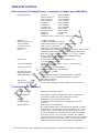
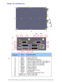
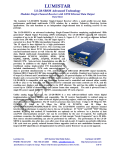
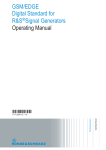
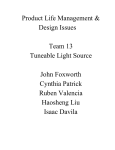
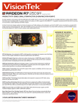
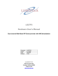
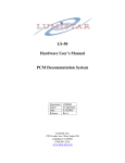
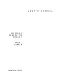
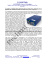
LUMISTAR
LS-28-DRSM Advanced Technology
Modular Dual-Channel Receiver/Combiner with CH10 Ethernet Data
Data Sheet
The Lumistar LS-28-DRSM Modular Dual-Channel Receiver/Combiner offers a small profile low-cost
high-performance multi-band multi-mode COTS solution for a modern Telemetry Receiving System
applications. The unit functions as an independent data & tracking receiver in one package.
The LS-28-DRSM is an advanced technology Dual-Channel Receiver/Combiner employing sophisticated
“fifth generation” Digital Signal Processing (DSP) technologies. The LS-28-DRSM supports independent
two-channel reception and/or combining of up to six RF bands including E, S, Lower-L, Upper-L, P, C,
(as well as customer defined bands from 250 MHz to 6
GHz). Each RF input is converted to a fixed 70 MHz
intermediate frequency (IF). These IF signals are then
digitized by a two-channel digital receiver. The IF
receiver provides optional combining as well as 2-channel
independent mode operation. The unit has provision for
direct PCM bit-synchonization from external sources as
well for Combined or Independent channel data. Digital
multi-mode demodulation options include Multi-Symbol
PCM/FM, SOQPSK, BPSK, QPSK, OQPSK, SQPSK,
AQPSK, AUQPSK, PCM/PM, and Multi-H CPM. Subcarrier(s) demodulation can also be provided. In addition
to the digital FM demodulation, traditional analog singlesymbol FM demodulation is included. PCM code converted output data is provided simultaneously to
TTL and high speed differential (RS422/485 signal standards). Optional IRIG Chapter10 UDP time
stamped data outputs are available. Standard user features such as O-scope Eye Pattern and
Constellation diagram displays, IF spectral displays at 70 MHz, Bit Error Rate Reader and a very
powerful “onboard 70 MHz signal modulator” are included at no additional cost. The LS-28-DRSM is
compatible with any Operating System and is controlled and statused either serially (USB or 232) or via
Ethernet. All Ethernet receiver command and status controls are TCP, and the resulting user displays
and data streaming is via UDP ethernet. The unit has the ability to optionally record up to 128GB of
demodualted data (minor frame time stamped) for each channel (CH1/CH2/Combined). The unit is
powered from a single DC power supply from +9V to +42V, consuming approximately 32 W.
Unlike analog legacy receivers, the LS-28-DRSM is a true software-defined radio whose digital
implementation is highly flexible and expandable. The IF receiver/combiner functionality is realized
using an architecture employing five state-of-the-art digital processing engines, which can operate as a
single or dual channel receiver/combiner. The IF receiver processes data rates from 1 kbps to 30 Mbps
for MS-PCM/FM, 1 Kbps to 30 Mbps for BPSK & PCM/PM, and 50 Mbps for
QPSK/OQPSKSQPSK/SOQPSK/Mutli-H CPM. The LS-28-DRSM sensitivity and adjacent channel
interference performance is superior due to the use of hardware IF “SAW” and DSP “FIR” filtering
method. By using this method, IF bandwidths are optimaly set by software “as a function of data
rate/PCM code/modulation format”, but can be overridden by the user if required. For multi-path
avoidance scenarios, the digital combiner operates at fade margin “break frequencies” up to 50 KHz.
Best source selection/combining can also be performed via software. The performance of the LS-28DRSM is repeatable, day-after-day, year-after-year, from unit-to-unit. It requires no periodic calibration.
Life cycle costs are greatly reduced because future upgrades (such as new modulation formats) or an
improved DSP algorithm are all implemented via software and/or firmware via an on-site upgrade.
Lumistar, Inc.
PHONE: 760-431-2181
2270 Camino Vida Roble Suite L
FAX: 760-431-2665
EMAIL: [email protected].
Specifications are subject to change. Please verify the latest specifications at time of order.
Carlsbad, CA 92011
http://www.lumi-star.com
5-28-15
SPECIFICATIONS:
Down-Converter/Tracking Receiver (2 each, up to six bands up to 6000 MHz):
RF Input Frequency:
S-band (S):
2200-2400 MHz
NATO E-Band (E):
2185-2485 MHz
Upper L-Band (U):
1710-1850 MHz
Lower L-Band (L):
1435-1540 MHz
C1 band (C1):
4400-4940 MHz
C2 band (C2):
5091-5150 MHz
C2e band (C2e):
5091-5250 MHz
CIF band (CIF):
400-1150MHz
CIFe band (CIFe):
300-1150 MHz
P-band (P):
215-320 MHz
70 MHz (I)
70 MHz
(Custom RF bands available, please consult the factory)
Input Level:
Maximum Input Level:
Tuner Resolution:
Frequency Accuracy:
Noise Figure:
IF Filters:
+10 dBm to threshold
+29 dBm (self-protection at startup)
50 KHz (consult factory for tighter resolution option)
0.001% typical, 0.002% max
5 dB (max); 3-4 dB (typical, near threshold)
SAW and FIR filters, default bandwidth auto- selected by “data rate, PCM
code and modulation format”, or user over-ride programmable filters.
Eight SAW pre-selection filters (0.25, 0.50, 1, 2, 5, 10, 20, 40 MHz)
Precision digital FIR filtering employed at demodulation input
<10 KHz resolution bandwidth
Exceeds requirements for ARTM Tier II phase noise
(< -90 dBc/Hz typ at 10 KHz)
Programmable over any portion, -4V to +4V, Linear, Pos/Neg
CH1/CH2 & Combined
Selectable: 0.1, 1, 10, 100, 1000 mSec
Programmable between 0.1 and 6500 mSec
120 dB (+10 to -110 dBm)
> +10 dBm
DC to 50 KHz bandwidth, programmable output vs. AM depth
(Typical 2V p-p for 50% modulation depth in to 75 ohms)
CH1/CH2 & Combined
32 each lowpass filters
exceeds IRIG requirements, contact Lumistar for more information
Phase Noise:
AGC Slope and Range:
AGC Time Constants:
RF Input AGC Range:
Input Compression:
AM Demodulation:
AM Filtering:
Adj Channel Interference:
Pre-D and Post-D Combiners:
Combiner Types:
Digital Pre-D, Post-D, Pre & Post
Combining Modes:
Optimal Ratio (combining algorithm based upon measured S/N for
each channel), Equal Gain, or Best Channel Select modes
Polarization, Frequency and Spatial Diversity
> 2.6 dB typical for Optimal Select (equal RF input levels near
threshold)
50 KHz minimum for 30 dB fades.
The digital combiner employs a fast DSP-based algorithm to provide
“Optimal Ratio” combined signal based upon real-time CH1 v. CH2
“Signal to Noise” measurements. The IF combiner does not require
slow AGC information for combining decision and it is not a simple
“best-source selector” but a true diversity combiner. The combiner
operates with a break frequency of > 50 KHz with worst case multipath
fade scenarios (such as –sin/sin AM for CH1 vs. CH2). The combiner
supports polarization, frequency and spatial diversity applications.
Modes:
S/N Improvement:
Break Frequency:
The Lumistar name, logo, trademarks, IP and products are licensed to Harmonix Systems Inc.
LUMISTAR
Demodulator Outputs (3 Each)
Demodulation Formats:
Multi-symbol PCM/FM, PCM/PM, BPSK, QPSK, SQPSK, SOQPSK,
OQPSK, AQPSK, AUQPSK, Multi-H CPM, Single-symbol PCM FM,
Analog Video FM, Subcarriers
Analog Video FM supports NTSC and PAL Video
Data Rates:
1 kbps – 30 Mbps (Multi-symbol PCM/FM)
50kbps – 20 Mbps (Single-symbol PCM/FM)
1 kbps – 30 Mbps (BPSK, PCM/PM)
1 kbps - 50 Mbps (QPSK, OQPSK, SQPSK, AQPSK, AUQPSK)
5kbps – 50Mbps (SOQPSK-TG)
100kbps – 50Mbps (Multi-H CPM)
Bit Syncs:
Three Independent Data/Clock Outputs for
CH1/CH2 & Combined
TTL and High-speed RS-422 available simultaneously on each channel
>3V peak in to 50 ohms
CH10 UDP Data Streaming:
Data is converted to CH10 format, time stamped and broadcast via
Ethernet port (optional)
Code Conversion:
NRZ-L/M/S, Bi-Φ L/M/S, RZ, DM-M/S, MDM-M/S, Diff Bi-Φ M/S,
RNRZ-LMS in (11, 15, 17, and 23), Inverted state of all PCM codes
listed
Standard Features:
Internal IF Modulator:
Internal 70 MHz Digital IF Modulator for loop-back self-test of the
receiver. Power output from 0 to -80 dBm. Formats include PCM/FM,
PCM/PM. BPSK, QPSK, OQPSK, SQPSK, SOQPSK, AUQPSK,
AQPSK, and Multi-h CPM, with data rates from 10 bps to 10 Mbps
(for FM/PM/BPSK) and 20 Mbps for all QPSK formats and Multi-H
CPM. Includes precision calibrated noise feature, output code selection
(NRZ-L/M/S, Bi-Phase L/M/S, DMM/S, and RNRZ15), external
modulation input, internal PRN pattern generation, adjustable
deviation, and Convolutional encoding. Separate “70 MHz to RF
upconverter” available to support RF bands.
Multi-symbol PCM/FM:
Improves BER performance by approx. > 2.5 dB vs. standard PCM/FM
Constellation Displays:
for all PSK formats
Eye Pattern Displays:
for all formats
Bit Error Rate TX/RX:
Six Receivers (CH1/CH2/Combined, I and Q for each stream),
Two PRN Generators (I and Q)
IF Spectrum Displays:
Displays 70 MHz IF Spectrum, has typical spectrum analyzer controls
and capabilities (such as Span. Averaging, Ref Level, Max Hold,
Clear/Write, Averaging, etc…). All displays can be captured via
“Screen-Shot” hardcopy feature, available in JPG file format.
IRIG Pre-D
Supports IRIG Pre-D Recording and Playback
Lumistar, Inc.
PHONE: 760-431-2181
2270 Camino Vida Roble Suite L
FAX: 760-431-2665
EMAIL: [email protected].
Specifications are subject to change. Please verify the latest specifications at time of order.
Carlsbad, CA 92011
http://www.lumi-star.com
5-28-15
Control / Time Interfaces:
Serial interface for control and general status only with USB 2.0 or
RS232 format. Ethernet interface supports 10/100/1000 Mbps rates.
IPv4, UDP (including multi-cast), TCP, ARP, ICMP, IGMP, PTP, and
HTTP. Ethernet provides multiple sockets for data, control and status.
Serial interface operates simultaneously with Ethernet interface.
IRIG A, B, or G input/output, selectable AC or DC coupled, Ethernet
IEEE 1588 with trigger input and clock interfaces
Data Archive Storage:
Optional; 32, 64 or 128 GB per channel x 3, Solid state NAND flash
memory, removable (14.2 hours per channel x 3 at 20 Mbps/channel).
Optional Features:
Lumistar offers various frequency bands, demodulation formats, Ch 10 Ethernet Data Streaming, Data
Archive, and decoding as options. Ordering information is in parenthesis.
Pricing is dependent upon the customer selection of these options. Some examples are listed below:
o Demodulation Formats:
o PCM/FM only (-M1), SOQPSK (-M2), PCM/FM and SOQPSK only (-M6)
o PCM/FM, BPSK, QPSK, OQPSK, AQPSK, SQPSK, SOQPSK, and PM (-M3)
o M3 formats plus AUQPSK (-M4),
o BPSK, QPSK, OQPSK, SOQPSK, PM with sub-carrier (M5)
o PCM/FM, SOQPSK and Multi-h CPM (-M7)
o CH10 Data Broadcast, Time Stamped (-C10E)
o Viterbi decoding (-V2)
o Reed-Solomon (-RS2)
o Soft Bit Decision Outputs (-SB3)
o Space Time Coding (-SC3)
o LDPC Coding (-LD3)
o Sub-carrier (-S2)
o AQPSK (-A2)
o Viterbi and Reed-Solomon Decoding (-VRS2)
o IRIG Pre-D Record/Playback (-IRP)
Environmental:
Operating Temperature:
Storage Temperature:
Operating Humidity:
Storage Humidity:
Operational Scenario:
-20o to +70o C
-40o to +85o C
0 to 90% (Non-condensing)
Protect from excessive moisture and contamination
Ground or Airborne based
Physical and Power:
Size:
Weight:
Chassis Material:
Power Supply:
Transient Protection:
Status Monitoring:
6.00” x 4.00” x 1.70” inches
4 pounds (8.8 Kg) typical
Aluminum, T-6061
+9 to +42 V at approx. 30 Watts (mode dependent)
Surge Protection up to 50 KV at 100 A
Continuous Temperature, Voltage & Current
The Lumistar name, logo, trademarks, IP and products are licensed to Harmonix Systems Inc.
LUMISTAR
Ordering Information:
Model Number Examples:
LS-28-DRSM-M1LS
LS-28-DRSM-M2UE
LS-28-DRSM-M6S
LS-28-DRSM-M6LU-V2
LS-28-DRSM-M3S
LS-28-DRSM-M6LUSC
LS-28-DRSM-M7LS
PCM/FM format, lower-L and S bands
SOQPSK format, upper-L and E-bands
PCM/FM & SOQPSK formats, S-band
PCM/FM & SOQPSK, with Viterbi, Lower L and Upper L bands
PCM/FM, BPSK, QPSK, OQPSK, SOQPSK, PCM/PM, S-band
PCM/FM & SOQPSK, lower/upper L bands, S and C bands
PCM/FM, SOQPSK, Multi-h CPM, lower-L and S bands
Frequency Band Examples:
S-band:
NATO E-Band:
Upper L-Band:
Lower L-Band:
C1 band:
C2e band:
C to IF band (CIF):
P-band:
N-band:
I-band:
2200-2400 MHz
2185-2485 MHz
1710-1850 MHz
1435-1540 MHz
4400-4940 MHz
5091-5250 MHz
400-1150 MHz
215-320 MHz
830-1130 MHz
70 MHz
Other Options:
CH10 Ethernet Data Streaming:
Viterbi Decoding:
Reed-Solomon Decoding:
Viterbi & Reed-Solomon:
Soft Bit Decision Outputs:
Data Archive Storage:
Add “-C10E” suffix to end of model number
Add “-V2” suffix to end of model number
Add “-RS2” suffix to end of model number
Add “-VRS2” suffix to end of the model number
Add “-SB2” suffix to the end of the model number
Add “-D32 for 32 GB”, “-D64” for 64 GB, “-D128” for 128 BG
This is a partial list of all possible options.
Please consult Lumistar Sales Engineering to define the exact model required.
For additional technical information please see the User Manual for LS-28-DRSM
Lumistar, Inc.
PHONE: 760-431-2181
2270 Camino Vida Roble Suite L
FAX: 760-431-2665
EMAIL: [email protected].
Specifications are subject to change. Please verify the latest specifications at time of order.
Carlsbad, CA 92011
http://www.lumi-star.com
5-28-15
Outline, I/O and Dimensions:
The Lumistar name, logo, trademarks, IP and products are licensed to Harmonix Systems Inc.