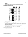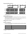
1
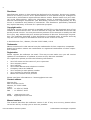
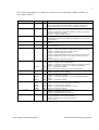
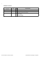
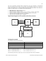
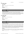
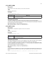
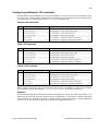
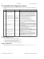
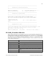
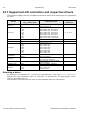
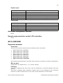
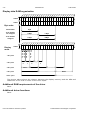
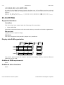
321
Hardware configuration
This driver accesses the hardware with a simple bus interface as described in Chapter
20: "Low-Level Configuration". The following table lists the macros which must be
defined for hardware access:
Macro
LCD_INIT_CONTROLLER
LCD_READ_A0
LCD_READ_A1
LCD_WRITE_A0
LCD_WRITE_A1
Explanation
Initialization sequence for the LCD controller.
Read a byte from LCD controller with A-line low.
Read a byte from LCD controller with A-line high.
Write a byte to LCD controller with A-line low.
Write a byte to LCD controller with A-line high.
Additional configuration switches
The following table shows optional configuration switches available for this driver:
Macro
Explanation
LCD_CACHE
When set to 0, no display data cache is used, which slows down the
speed of the driver. Default is 1 (cache activated).
LCD_SUPPORT_CACHECONTROL
When set to 0, the cache control functions of
LCD_L0_ControlCache() driver API are disabled.
Special requirements for certain LCD controllers
None.
22.7 LCD6642X
Supported hardware
Controllers
This driver has been tested with the following LCD controllers:
•
•
Hitachi HD66420
Hitachi HD66421
It should be assumed that it will also work with any controller of similar organization.
Bits per pixel
Supported color depth is 2 bpp.
Interfaces
The driver supports 8-bit parallel (simple bus) interfaces.
User's & reference manual for µC/GUI
© 2002 Micrium Technologies Corporation