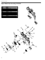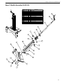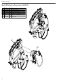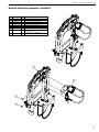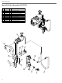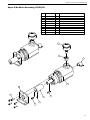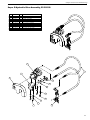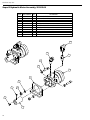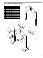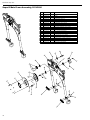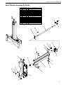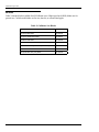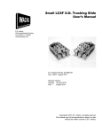
1
Guillotine Pipe Saw User’s Manual E.H. Wachs 600 Knightsbridge Parkway Lincolnshire, IL 60069 www.ehwachs.com E.H. Wachs Part No. 03-MAN-01 Rev. B, April 2014 Copyright © 2014 E.H. Wachs. All rights reserved. This manual may not be reproduced in whole or in part without the written consent of E.H. Wachs. EU Declaration OF CONFORMITY WITH COUNCIL DIRECTIVE 2006/42/EC Issue Details: DATE: 1/1/2011 Directives: Machinery Safety Directive 2006/42/EC Conforming Machinery: Guillotine Pipe Saw: Model Number: 04-000-02, 04-000-03 (Model D) 24-000-02, 24-000-03 (Super C) 25-000-01, 25-000-03 (Super D) Place: E.H.Wachs, Lincolnshire, IL USA Model D Guillotine, Wuper C Guillotine, Super D Guilotine Serial Number: Manufacturer: Responsible Representative: Harmonised Standards & Other Technical Standards/Specifications Applied or Referenced: Provisions with which Conformity is Declared: E.H. Wachs 600 Knightsbridge Parkway Lincolnshire IL 60069 USA Orbitalum Tools GmbH Josef-Schüttler-Str. 17, 78224 Singen Germany Tel. +49 (0) 7731 - 792 872 Fax +49 (0) 7731 - 792 566 EN ISO 12100-1:2003 + A1:2009 EN ISO 12100-2:2003 + A1:2009 EN 60204-1:2006 (for electric machines) EN ISO 13857:2008 EN 982:1996 + A1:2008 (for hydrailic machines) EN 983:1996 (for pneumatic machines) EN 13732-1:2006 EN ISO 14121-1:2007 EN ISO 13850:2008 (for pneumatic machines) Essential Health and Safety Requirements of Annex 1 of the Machinery Directive We hereby certify that the machinery descrived above conforms to the provisions of Council Directive 2006/42/EC on the approximation of the laws of the Member States relating to the safety of machinery. Signed: Signatory: Pete Mullally Quality Manager E.H. Wachs Table of Contents Table of Contents Chapter 1: About This Manual . . . . . . . . . . . . . . . . . . . . . . . . . . . . . . . . . . . . . . . . . . . . . . . . . . . 1 Purpose of This Manual . . . . . . . . . . . . . . . . . . . . . . . . . . . . . . . . . . . . . . . . . . . . . . . . . . . . . . . . . . 1 How to Use The Manual. . . . . . . . . . . . . . . . . . . . . . . . . . . . . . . . . . . . . . . . . . . . . . . . . . . . . . . . . . 1 Symbols and Warnings . . . . . . . . . . . . . . . . . . . . . . . . . . . . . . . . . . . . . . . . . . . . . . . . . . . . . . . . . . . 2 Manual Updates and Revision Tracking. . . . . . . . . . . . . . . . . . . . . . . . . . . . . . . . . . . . . . . . . . . . . . 3 Chapter 2: Safety. . . . . . . . . . . . . . . . . . . . . . . . . . . . . . . . . . . . . . . . . . . . . . . . . . . . . . . . . . . . . . . 5 Safe Operating Guidelines. . . . . . . . . . . . . . . . . . . . . . . . . . . . . . . . . . . . . . . . . . . . . . . . . . . . . . . . 5 Safe Operating Environment. . . . . . . . . . . . . . . . . . . . . . . . . . . . . . . . . . . . . . . . . . . . . . . . . . . . 6 Operating and Maintenance Safety. . . . . . . . . . . . . . . . . . . . . . . . . . . . . . . . . . . . . . . . . . . . . . . 6 Hydraulic Powered Equipment. . . . . . . . . . . . . . . . . . . . . . . . . . . . . . . . . . . . . . . . . . . . . 6 Pneumatic Powered Equipment. . . . . . . . . . . . . . . . . . . . . . . . . . . . . . . . . . . . . . . . . . . . . 7 Loss or Shut-Off of Power Supply. . . . . . . . . . . . . . . . . . . . . . . . . . . . . . . . . . . . . . . . . . . . . 7 Safety Alerts in This Manual. . . . . . . . . . . . . . . . . . . . . . . . . . . . . . . . . . . . . . . . . . . . . . . . . . . . 7 Protective Equipment Requirements. . . . . . . . . . . . . . . . . . . . . . . . . . . . . . . . . . . . . . . . . . . . . . 8 Protective Clothing. . . . . . . . . . . . . . . . . . . . . . . . . . . . . . . . . . . . . . . . . . . . . . . . . . . . . . . . 8 Eye Protection. . . . . . . . . . . . . . . . . . . . . . . . . . . . . . . . . . . . . . . . . . . . . . . . . . . . . . . . . . . . 8 Hearing Protection . . . . . . . . . . . . . . . . . . . . . . . . . . . . . . . . . . . . . . . . . . . . . . . . . . . . . . . . 8 Safe Operation of the Guillotine Pipe Saw . . . . . . . . . . . . . . . . . . . . . . . . . . . . . . . . . . . . . . . . . . . . 9 Intended Uses . . . . . . . . . . . . . . . . . . . . . . . . . . . . . . . . . . . . . . . . . . . . . . . . . . . . . . . . . . . . . . . 9 Proper Use of the Guillotine . . . . . . . . . . . . . . . . . . . . . . . . . . . . . . . . . . . . . . . . . . . . . . . . . . . . 9 Misuse. . . . . . . . . . . . . . . . . . . . . . . . . . . . . . . . . . . . . . . . . . . . . . . . . . . . . . . . . . . . . . . . . . 9 Potential Hazards . . . . . . . . . . . . . . . . . . . . . . . . . . . . . . . . . . . . . . . . . . . . . . . . . . . . . . . . . . . . 9 Guidelines for Safe Setup, Operation, and Service. . . . . . . . . . . . . . . . . . . . . . . . . . . . . . . . . . 10 Pre-Operation Checklist . . . . . . . . . . . . . . . . . . . . . . . . . . . . . . . . . . . . . . . . . . . . . . . . . . . 10 Operating Safety. . . . . . . . . . . . . . . . . . . . . . . . . . . . . . . . . . . . . . . . . . . . . . . . . . . . . . . . . 11 Service Checklist. . . . . . . . . . . . . . . . . . . . . . . . . . . . . . . . . . . . . . . . . . . . . . . . . . . . . . . . . 11 Safe Lifting and Handling. . . . . . . . . . . . . . . . . . . . . . . . . . . . . . . . . . . . . . . . . . . . . . . . . . . . . 11 Safety and Operation Labels. . . . . . . . . . . . . . . . . . . . . . . . . . . . . . . . . . . . . . . . . . . . . . . . . . . 11 Chapter 3: Introduction to the Equipment. . . . . . . . . . . . . . . . . . . . . . . . . . . . . . . . . . . . . . . . . 15 Overview of the Guillotine. . . . . . . . . . . . . . . . . . . . . . . . . . . . . . . . . . . . . . . . . . . . . . . . . . . . . . . 15 Machine Specifications. . . . . . . . . . . . . . . . . . . . . . . . . . . . . . . . . . . . . . . . . . . . . . . . . . . . . . . 16 Power Requirements. . . . . . . . . . . . . . . . . . . . . . . . . . . . . . . . . . . . . . . . . . . . . . . . . . . . . . . . . 17 Special-Order Options. . . . . . . . . . . . . . . . . . . . . . . . . . . . . . . . . . . . . . . . . . . . . . . . . . . . . . . . 17 Noise Levels. . . . . . . . . . . . . . . . . . . . . . . . . . . . . . . . . . . . . . . . . . . . . . . . . . . . . . . . . . . . . . . 17 Operating Envelopes. . . . . . . . . . . . . . . . . . . . . . . . . . . . . . . . . . . . . . . . . . . . . . . . . . . . . . . . . . . . 18 Super C, Pneumatic Drive (24-000-02). . . . . . . . . . . . . . . . . . . . . . . . . . . . . . . . . . . . . . . . . . . 19 Super C, Hydraulic Drive (24-000-03). . . . . . . . . . . . . . . . . . . . . . . . . . . . . . . . . . . . . . . . . . . 20 Model D, Pneumatic Drive (04-000-02). . . . . . . . . . . . . . . . . . . . . . . . . . . . . . . . . . . . . . . . . . 21 Model D, Hydraulic Drive (04-000-03). . . . . . . . . . . . . . . . . . . . . . . . . . . . . . . . . . . . . . . . . . . 22 E.H. Wachs Part No. 03-MAN-01, Rev. Bi Guillotine Pipe Saw Super D, Pneumatic Drive (25-000-01). . . . . . . . . . . . . . . . . . . . . . . . . . . . . . . . . . . . . . . . . . . 23 Super D, Hydraulic Drive (25-000-03). . . . . . . . . . . . . . . . . . . . . . . . . . . . . . . . . . . . . . . . . . . 24 Chapter 4: Assembly, Disassembly, and Storage . . . . . . . . . . . . . . . . . . . . . . . . . . . . . . . . . . . . 25 Storage/Shipping Containers. . . . . . . . . . . . . . . . . . . . . . . . . . . . . . . . . . . . . . . . . . . . . . . . . . . . . . 25 Storage Guidelines . . . . . . . . . . . . . . . . . . . . . . . . . . . . . . . . . . . . . . . . . . . . . . . . . . . . . . . . . . . . . 26 Chapter 5: Operating Instructions . . . . . . . . . . . . . . . . . . . . . . . . . . . . . . . . . . . . . . . . . . . . . . . 27 Installing the Blade. . . . . . . . . . . . . . . . . . . . . . . . . . . . . . . . . . . . . . . . . . . . . . . . . . . . . . . . . . . . . 27 Mounting the Saw on the Workpiece. . . . . . . . . . . . . . . . . . . . . . . . . . . . . . . . . . . . . . . . . . . . . . . . 27 Operating the Saw. . . . . . . . . . . . . . . . . . . . . . . . . . . . . . . . . . . . . . . . . . . . . . . . . . . . . . . . . . . . . . 29 Cutting Tips . . . . . . . . . . . . . . . . . . . . . . . . . . . . . . . . . . . . . . . . . . . . . . . . . . . . . . . . . . . . . . . 30 Cutting Lubrication. . . . . . . . . . . . . . . . . . . . . . . . . . . . . . . . . . . . . . . . . . . . . . . . . . . . . . . . . . 30 Chapter 6: Routine Maintenance. . . . . . . . . . . . . . . . . . . . . . . . . . . . . . . . . . . . . . . . . . . . . . . . . 31 Daily Maintenance . . . . . . . . . . . . . . . . . . . . . . . . . . . . . . . . . . . . . . . . . . . . . . . . . . . . . . . . . . . . . 31 Lubrication. . . . . . . . . . . . . . . . . . . . . . . . . . . . . . . . . . . . . . . . . . . . . . . . . . . . . . . . . . . . . . . . . . . 31 Chapter 7: Service and Repair. . . . . . . . . . . . . . . . . . . . . . . . . . . . . . . . . . . . . . . . . . . . . . . . . . . 33 Troubleshooting . . . . . . . . . . . . . . . . . . . . . . . . . . . . . . . . . . . . . . . . . . . . . . . . . . . . . . . . . . . . . . . 33 Chapter 8: Parts Lists and Drawings. . . . . . . . . . . . . . . . . . . . . . . . . . . . . . . . . . . . . . . . . . . . . . 35 Super C Guillotine, Pneumatic, 24-000-02. . . . . . . . . . . . . . . . . . . . . . . . . . . . . . . . . . . . . . . . 36 Super C Guillotine, Hydraulic, 24-000-03 . . . . . . . . . . . . . . . . . . . . . . . . . . . . . . . . . . . . . . . . 37 Super C Air Drive Assembly, 24-024-00. . . . . . . . . . . . . . . . . . . . . . . . . . . . . . . . . . . . . . . . . . 38 Super C Air Lubricator/Filter Assembly, 24-501-00. . . . . . . . . . . . . . . . . . . . . . . . . . . . . . . . . 39 Super C Air Motor Assembly, 24-502-00 . . . . . . . . . . . . . . . . . . . . . . . . . . . . . . . . . . . . . . . . . 40 Super C Hydraulic Drive Assembly, 24-025-00 . . . . . . . . . . . . . . . . . . . . . . . . . . . . . . . . . . . . 41 Super C Hydraulic Valve Assembly, 24-503-00 . . . . . . . . . . . . . . . . . . . . . . . . . . . . . . . . . . . . 42 Super C Hydraulic Motor Assembly, 24-504-00. . . . . . . . . . . . . . . . . . . . . . . . . . . . . . . . . . . . 43 Super C Frame Assembly, 24-399-00. . . . . . . . . . . . . . . . . . . . . . . . . . . . . . . . . . . . . . . . . . . . 44 Super C Saw Frame Assembly, 24-017-00 . . . . . . . . . . . . . . . . . . . . . . . . . . . . . . . . . . . . . . . . 45 Super C Main Frame Assembly, 24-018-00. . . . . . . . . . . . . . . . . . . . . . . . . . . . . . . . . . . . . . . . 46 Super C Saddle Assembly, 24-021-00. . . . . . . . . . . . . . . . . . . . . . . . . . . . . . . . . . . . . . . . . . . . 47 Model D Guillotine, Pneumatic, 04-000-02 . . . . . . . . . . . . . . . . . . . . . . . . . . . . . . . . . . . . . . . 48 Model D Guillotine, Hydraulic, 04-000-03. . . . . . . . . . . . . . . . . . . . . . . . . . . . . . . . . . . . . . . . 49 Model D Air Drive Assembly, 04-137-00. . . . . . . . . . . . . . . . . . . . . . . . . . . . . . . . . . . . . . . . . 50 Model D Air Motor Assembly, 04-029-00. . . . . . . . . . . . . . . . . . . . . . . . . . . . . . . . . . . . . . . . . 51 Model D Air Lubricator/Filter Assembly, 04-501-00 . . . . . . . . . . . . . . . . . . . . . . . . . . . . . . . . 52 Model D Hydraulic Drive Assembly, 04-305-00. . . . . . . . . . . . . . . . . . . . . . . . . . . . . . . . . . . . 53 Model D Hydraulic Motor Assembly, 04-502-00 . . . . . . . . . . . . . . . . . . . . . . . . . . . . . . . . . . . 54 Model D Hydraulic Valve Assembly, 04-503-00. . . . . . . . . . . . . . . . . . . . . . . . . . . . . . . . . . . . 55 Model D Frame Assembly, 04-399-00. . . . . . . . . . . . . . . . . . . . . . . . . . . . . . . . . . . . . . . . . . . . 56 Model D Saw Frame Assembly, 04-301-00. . . . . . . . . . . . . . . . . . . . . . . . . . . . . . . . . . . . . . . . 57 ii Part No. 03-MAN-01, Rev. B E.H. Wachs Table of Contents Model D Main Frame Assembly, 04-302-00. . . . . . . . . . . . . . . . . . . . . . . . . . . . . . . . . . . . . . . 58 Model D Saddle Assembly, 04-303-00 . . . . . . . . . . . . . . . . . . . . . . . . . . . . . . . . . . . . . . . . . . . 59 Super D Guillotine, Pneumatic, 25-000-01. . . . . . . . . . . . . . . . . . . . . . . . . . . . . . . . . . . . . . . . 60 Super D Guillotine, Hydraulic, 25-000-03 . . . . . . . . . . . . . . . . . . . . . . . . . . . . . . . . . . . . . . . . 61 Super D Air Drive Assembly, 25-137-00. . . . . . . . . . . . . . . . . . . . . . . . . . . . . . . . . . . . . . . . . . 62 Super D Air Motor Assembly, 25-029-00 . . . . . . . . . . . . . . . . . . . . . . . . . . . . . . . . . . . . . . . . . 63 Super D Air Lubricator/Filter Assembly, 25-501-00. . . . . . . . . . . . . . . . . . . . . . . . . . . . . . . . . 64 Super D Hydraulic Drive Assembly, 25-305-00 . . . . . . . . . . . . . . . . . . . . . . . . . . . . . . . . . . . . 65 Super D Hydraulic Motor Assembly, 25-502-00. . . . . . . . . . . . . . . . . . . . . . . . . . . . . . . . . . . . 66 Super D Hydraulic Valve Assembly, 25-503-00 . . . . . . . . . . . . . . . . . . . . . . . . . . . . . . . . . . . . 67 Super D Frame Assembly, 25-399-00. . . . . . . . . . . . . . . . . . . . . . . . . . . . . . . . . . . . . . . . . . . . 68 Super D Saw Frame Assembly, 25-301-00 . . . . . . . . . . . . . . . . . . . . . . . . . . . . . . . . . . . . . . . . 69 Super D Main Frame Assembly, 25-302-00 . . . . . . . . . . . . . . . . . . . . . . . . . . . . . . . . . . . . . . . 70 Super D Saddle Assembly, 25-303-00. . . . . . . . . . . . . . . . . . . . . . . . . . . . . . . . . . . . . . . . . . . . 71 Chapter 9: Accessories and Spare Parts . . . . . . . . . . . . . . . . . . . . . . . . . . . . . . . . . . . . . . . . . . . 73 Spare Parts. . . . . . . . . . . . . . . . . . . . . . . . . . . . . . . . . . . . . . . . . . . . . . . . . . . . . . . . . . . . . . . . . . . . 73 Blades. . . . . . . . . . . . . . . . . . . . . . . . . . . . . . . . . . . . . . . . . . . . . . . . . . . . . . . . . . . . . . . . . . . . . . . 74 Chapter 10: Ordering Information. . . . . . . . . . . . . . . . . . . . . . . . . . . . . . . . . . . . . . . . . . . . . . . 75 Ordering Replacement Parts. . . . . . . . . . . . . . . . . . . . . . . . . . . . . . . . . . . . . . . . . . . . . . . . . . . . . . 75 Repair Information . . . . . . . . . . . . . . . . . . . . . . . . . . . . . . . . . . . . . . . . . . . . . . . . . . . . . . . . . . . . . 75 Warranty Information. . . . . . . . . . . . . . . . . . . . . . . . . . . . . . . . . . . . . . . . . . . . . . . . . . . . . . . . . . . 76 Return Goods Address. . . . . . . . . . . . . . . . . . . . . . . . . . . . . . . . . . . . . . . . . . . . . . . . . . . . . . . . . . . 76 E.H. Wachs Part No. 03-MAN-01, Rev. Biii Guillotine Pipe Saw iv Part No. 03-MAN-01, Rev. B E.H. Wachs Chapter 1, About This Manual Chapter 1 About This Manual Purpose of This Manual This manual explains how to operate and maintain the Guillotine pipe saw. It includes instructions for set-up, operation, and maintenance. It also contains parts lists, diagrams, and service information to help you order replacement parts and perform user-serviceable repairs. The Guillotine pipe saw is available in three machine sizes. This manual describes operation and maintenance of all three models; specifications are in Chapter 3. Carefully read Chapter 2, Safety, and follow all guidelines for safe operation of the Guillotine saw. How to Use The Manual This manual is organized to help you quickly find the information you need. Each chapter describes a specific topic on using or maintaining your equipment. Use these instructions to operate and maintain the equipment. E.H. Wachs Part No. 03-MAN-01, Rev. B1 Guillotine Pipe Saw Symbols and Warnings The following symbols are used throughout this manual to indicate special notes and warnings. They appear in the outside column of the page, next to the section they refer to. Make sure you understand what each symbol means, and follow all instructions for cautions and warnings. Throughout this manual, refer to warnings, cautions, and notices with supplementary information. WARNING A WARNING alert with the safety alert symbol indicates a potentially hazardous situation that could result in serious injury or death. CAUTION A CAUTION alert with the safety alert symbol indicates a potentially hazardous situation that could result in minor or moderate injury. This is the safety alert symbol. It is used to alert you to potential personal injury hazards. Obey all safety messages that follow this symbol to avoid possible injury or death. This is the equipment damage alert symbol. It is used to alert you to potential equipment damage situations. Obey all messages that follow this symbol to avoid damaging the equipment or workpiece on which it is operating. CAUTION A CAUTION alert with the damage alert symbol indicates a situation that will result in damage to the equipment. IMPORTANT An IMPORTANT alert with the damage alert symbol indicates a situation that may result in damage to the equipment. 2 Part No. 03-MAN-01, Rev. B E.H. Wachs Chapter 1, About This Manual: Manual Updates and Revision Tracking NOTE This symbol indicates a user note. Notes provide additional information to supple ment the instructions, or tips for easier operation. Manual Updates and Revision Tracking Occasionally, we will update manuals with improved operation or maintenance procedures, or with corrections if necessary. When a manual is revised, we will update the revision history on the title page. Current versions of E.H. Wachs Company manuals are also available in PDF format. You can request an electronic copy of this manual by emailing customer service at [email protected]. You may have factory service or upgrades performed on the equipment. If this service changes any technical data or operation and maintenance procedures, we will include a revised manual when we return the equipment to you. Technical File Responsible Party The Guillotine pipe saw is manufactured by E.H. Wachs at the following address: E.H. Wachs 600 Knightsbridge Parkway Lincolnshire, IL 60069 U.S.A. The following organization is the responsible party for maintaining the Guillotine technical file in the EU: Orbitalum Tools GmbH Josef-Schüttler-Str. 17 78224 Singen Deutschland E.H. Wachs Part No. 03-MAN-01, Rev. B3 Guillotine Pipe Saw 4 Part No. 03-MAN-01, Rev. B E.H. Wachs Chapter 2, Safety Chapter 2 Safety E.H. Wachs takes great pride in designing and manufacturing safe, high-quality products. We make user safety a top priority in the design of all our products. Read this chapter carefully before operating your E.H. Wachs equipment. It contains important safety instructions and recommendations. Safe Operating Guidelines Follow these guidelines for safe operation of all E.H. Wachs equipment. Look for this symbol throughout the manual. It indicates a personal injury hazard. • READ THE OPERATING MANUAL. Make sure you understand all setup and operating instructions before you begin. Keep this manual with the machine. • INSPECT MACHINE AND ACCESSORIES BEFORE USE. Before starting the machine, look for loose bolts or nuts, leaking lubricant, rusted components, and any other physical conditions that may affect operation. Properly maintaining the machine can greatly decrease the chances for injury. • ALWAYS READ STICKERS AND LABELS. Make sure all labels and stickers are in place, clearly legible, and in good condition. Refer to “Safety Labels” later in this chapter for label locations on the machine. Replace any damaged or missing safety labels; see Chapter 10 for ordering information. • KEEP CLEAR OF MOVING PARTS. Keep hands, arms, and fingers clear of all rotating or moving parts. Always turn the machine off and disconnect the power source before doing any adjustments or service. • SECURE LOOSE CLOTHING AND JEWELRY. Secure or remove loose-fitting clothing and jewelry, and securely bind long hair, to prevent them from getting caught in moving parts of the machine. • FOLLOW SAFE PROCEDURES FOR HANDLING LUBRICANTS. Refer to the manufacturer’s instructions and the Material Safety Data Sheets. E.H. Wachs Part No. 03-MAN-01, Rev. B5 Guillotine Pipe Saw Safe Operating Environment • Do not use this equipment in a potentially explosive atmosphere. Fire or explosion could result, with the risk of serious injury or death. • Provide adequate lighting to use the equipment, in accordance with worksite or local regulations. • KEEP WORK AREA CLEAR. Keep all clutter and nonessential materials out of the work area. Only people directly involved with the work being performed should have access to the area. Operating and Maintenance Safety • This equipment is to be operated and maintained only by qualified, trained personnel. • Make sure the equipment is stable when attached to the workpiece for the operation. Ensuring stability of the installed tool is the responsibility of the operator. • Make sure the workpiece is supported adequately for installation of the equipment. This includes supporting any workpiece “fall-off” section when severing the workpiece. Ensuring support of the workpiece is the responsibility of the operator. • Tooling on any cutting equipment—including lathe tools, saw blades, milling tools, etc.—may get very hot. Do not touch tooling until you have made sure it is cool enough to handle. • Wear gloves when removing or cleaning up chips and cutting debris. Chips can be very sharp and cause cuts. • Before performing any service on the equipment, disconnect the power source. Follow all lock-out/tag-out procedures required at the worksite. Hydraulic Powered Equipment • Hydraulic components such as hoses, motors, and manifolds will get hot during operation and may cause burns. Do not touch hydraulic components, except for operator controls, during or after operating the machine. WARNING Injection of hydraulic fluid through the skin is a serious injury that can result in infection, tissue damage, and possible loss of limb. Seek medical treatment immediately. First aid is not sufficient treatment for injection injury. • Hydraulic injection injury—A pinhole in a hydraulic hose or fitting can eject fluid with enough force to pierce skin. Check hoses and fittings regularly for leaks. Do not use bare hands to check for leaks while the system is pressurized. If you suspect a leak, move a piece of paper or cardboard at least 6 inches (15 cm) over the suspicious area and watch for fluid spraying on the surface. 6 Part No. 03-MAN-01, Rev. B E.H. Wachs Chapter 2, Safety: Safe Operating Guidelines Pneumatic Powered Equipment • Air motors may get hot during operation and may cause burns. Do not touch the air motor, except for operator controls, during or after operating the machine. • Before disconnecting the air line from the equipment, always turn off air at the source and bleed all residual air pressure at the air motor. Loss or Shut-Off of Power Supply • If the power source to the equipment is lost, disconnect power from the equipment and lock out the power supply immediately to prevent accidental restarting of the machine. • ELECTRIC POWERED EQUIPMENT—If the electric drive shuts off because of its built-in thermal protection, disconnect the motor from the power source immediately. • For all power sources, follow all lock-out/tag-out procedures required at the worksite when disconnecting or servicing the equipment. Safety Alerts in This Manual The following alerts are used throughout this manual to indicate operator safety hazards. In all cases, these alerts include a notice describing the hazard and the means to avoid or reduce risk. Carefully read all safety alerts. This icon is displayed with any safety alert that indicates a personal injury hazard. WARNING This safety alert, with the personal injury hazard symbol, indicates a potentially hazardous situation that, if not avoided, could result in death or serious injury. CAUTION This safety alert, with the personal injury hazard symbol, indicates a potentially hazardous situation that, if not avoided, could result in minor or moderate injury. E.H. Wachs Part No. 03-MAN-01, Rev. B7 Guillotine Pipe Saw Protective Equipment Requirements Protective Clothing Wear safety shoes when operating or servicing the equipment. Serious injury could result from dropping the machine or its components. Do not wear gloves while operating the machine. Gloves can become entangled in moving parts, resulting in serious injury. Gloves may be worn when setting up the machine or cleaning up after the operation, but take them off when operating the machine. NOTE Gloves should be worn when cleaning up chips and other cutting debris. Chips can be very sharp and can cause serious cuts. Do not wear gloves when the machine is operating. Eye Protection Always wear impact-resistant eye protection while operating or working near this equipment. For additional information on eye and face protection, refer to Federal OSHA regulations, 29 Code of Federal Regulations, Section 1910.133., Eye and Face Protection and American National Standards Institute, ANSI Z87.1, Occupational and Educational Eye and Face Protection. Hearing Protection This equipment can produce noise levels above 80 dB. Hearing protection is required when operating the equipment. The operation of other tools and equipment in the area, reflective surfaces, process noises, and resonant structures can increase the noise level in the area. For additional information on hearing protection, refer to Federal OSHA regulations, 29 Code of Federal Regulations, Section 1910.95, Occupational Noise Exposure and ANSI S12.6 Hearing Protectors. 8 Part No. 03-MAN-01, Rev. B E.H. Wachs Chapter 2, Safety: Safe Operation of the Guillotine Pipe Saw Safe Operation of the Guillotine Pipe Saw Intended Uses The Guillotine pipe saw is designed to be clamped onto an in-line or open-ended pipe (using either a chain clamp or hydraulic autoclamp), and cut through the pipe using an oscillating saw motion. Make sure to follow all safety guidelines and procedures required for machining operations at the work site, including personal protective equipment (PPE). Do not use the Guillotine pipe saw in a manner that violates these guidelines. Proper Use of the Guillotine • The Guillotine should only be used by trained, qualified operators. • The workpiece must be within the operating capacity of the Guillotine model you are using. See operating envelope information and drawings in Chapter 3. • Make sure the operating environment allows you to mount the machine securely and squarely on the workpiece. • Make sure there is adequate clearance around the Guillotine and workpiece to operate the machine controls as described in the operating instructions (Chapter 5). • Mount the Guillotine in an orientation that allows convenient connection of the drive power supply (air or hydraulic). • Mount the Guillotine so that the feed drive can be operated conveniently, without reaching across moving parts. • Use the Guillotine only on empty, depressurized pipe. Misuse • Do not attempt to mount or operate the Guillotine on any workpiece to which it cannot be securely clamped. • Do not attempt to mount or operate the Guillotine on any workpiece that is not stable enough to hold the machine. • Do not mount the Guillotine on the “fall-off” side of the cut line, unless you adequately rig and support the Guillotine and workpiece. • Do not disable any safety feature of the Guillotine or remove any safety labeling. Replace worn or damaged safety labels immediately. (See “Safety and Operation Labels” later in this chapter.) Potential Hazards Figure 2-1 illustrates potential hazards of operating the Guillotine pipe saw. Refer to the description of each hazard for guidelines on safe operation. E.H. Wachs Part No. 03-MAN-01, Rev. B9 Guillotine Pipe Saw Figure 2-1. Potential operating hazards of the Guillotine saw. See the descriptions in the side column. A. Moving Parts Hazard—Keep away from the oscillating saw bow and all moving parts while the machine is operating. B. Pipe Saddle Mounting Point—Keep hands and feet clear when mounting and moving the saw on the workpiece. C. Cutting Zone—Keep away from the saw blade while the machine is operating. Use care when handling the saw blade and cutting debris. Guidelines for Safe Setup, Operation, and Service Pre-Operation Checklist Every time you use the Guillotine, perform the following checks to make sure it is in good operating condition: • Check that all safety components are operating properly. • Inspect it for damage or wear that could affect operation and safe use of the machine. Repair any defective component before using the machine. • Make sure the machine is clean and properly lubricated. • Make sure that the blade is sharp and in good condition. A poor quality blade can cause difficult cutting and the possibility of machine malfunction and/or injury. • Check power connections (pneumatic or hydraulic) to make sure they are in good condition. 10 Part No. 03-MAN-01, Rev. B E.H. Wachs Chapter 2, Safety: Safe Operation of the Guillotine Pipe Saw Operating Safety • Stop the Guillotine cutting motion to adjust the workpiece (shim, wedge, clear chips, etc.) or make any machine adjustments. • Use a support structure or catch device to prevent the cut-off piece of the pipe from falling. • Keep air and hydraulic hoses away from moving parts while operating the machine. Service Checklist • Disconnect power from the Guillotine during service. • Retract the saw bow before performing service. Do not disassemble any components of the saw with the blade in the workpiece. Safe Lifting and Handling Use care when lifting the Guillotine saw to avoid injury. All Guillotine models are too heavy to be lifted by one person. A lifting device (crane or hoist) is required for lifting and mounting the saw. Use the lift eyes on the saw to lift it. Do not attach the lifting device to other components. • It is the responsibility of the end user to determine whether a machine or assembly can be lifted by two or more people. A lifting device is recommended for machines or assemblies that cannot be handled easily by two people. • Do not rig or lift the Guillotine while power is attached. Safety and Operation Labels The following labels are provided on the Guillotine. If any of these labels is damaged or missing, replace it immediately. See Chapter 10 for ordering information. Figure 2-2. The blade direction labels are attached to both sides of the saw frame assembly. Make sure to install the blade with the saw teeth in the correct direction. (Part no. 03-113-00.) E.H. Wachs Part No. 03-MAN-01, Rev. B11 Guillotine Pipe Saw Figure 2-3. The cam wheel label is on the back of th main assembly, illustrating the direction of rotation. (Part no. 03-113-01.) Figure 2-4. The feed direction label shows the operating direction for the feed handle. (Part no. 03-113-03.) Figure 2-5. The moving parts warning label is attached in 2 places on the saw frame assembly. (Part no. 03-113-04.) 12 Part No. 03-MAN-01, Rev. B E.H. Wachs Chapter 2, Safety: Safe Operation of the Guillotine Pipe Saw Figure 2-6. The blade hazard label is attached in 2 places on the saw frame assembly. (Part no. 03-113-05.) Figure 2-7. The grease fitting label is attached to the yoke grease cover on the saw frame assembly. Remove the cover to grease the yoke. (Part no. 03-113-06.) E.H. Wachs Part No. 03-MAN-01, Rev. B13 Guillotine Pipe Saw Figure 2-8. The pressure and tank hydraulic fitting labels are attached to the feed weldment of hydraulic Guillotine models. The arrows indicate hydraulic flow direction through the ports. (Part numbers 03-113-07 and 03-113-08.) Figure 2-9. The Read Manual label is attached at the top of the main frame assembly. (Part no. 90-900-01.) 14 Part No. 03-MAN-01, Rev. B E.H. Wachs Chapter 3, Introduction to the Equipment Chapter 3 Introduction to the Equipment Overview of the Guillotine The Guillotine pipe saw product line includes three models for cutting pipes ranging from 2” to 24” (51-610 mm) diameter. The Guillotine will cut pipes of all materials, and can also be used to cut solids such as bar stock and rails. The Guillotine mounts directly to the pipe using a V-shaped saddle with a clamping chain. The saddle is precisely machined for automatic square alignment when the chain is tightened. The saw can be mounted in any orientation to horizontal or vertical pipe. The blade operates on an oscillating bow that lifts the blade out of the cut on the return stroke, increasing blade life. On/off and speed controls are provided for the cutting drive. The oscillating bow is mounted on a feed screw for feeding the saw. A manual feed handle at the top of the machine allows the operator to feed the blade into the workpiece as the machine cuts. Three standard Guillotine pipe saw models are available: • Super C, with a pipe capacity of 2”-12” (51-305 mm) • Model D, with a pipe capacity of 10”-16” (254-406 mm) • Super D, with a pipe capacity of 10”-24” (254-610 mm). E.H. Wachs Part No. 03-MAN-01, Rev. B15 Guillotine Pipe Saw Figure 3-1. The photo shows the Super D, Model D, and Super C Guillotine pipe saws. Machine Specifications Table 1 lists the operating capacities of the Guillotine saw models. See the operating envelope drawings at the end of this chapter for all dimensional details. Table 1: Guillotine Saw Capacities 16 Model Pipe Capacity Solids Capacity Cutting Stroke Weight Super C 2”-12” (51-305 mm) 2”-12.75” (51-324 mm) 2” (51 mm) 135 lb (62 kg) Model D 10”-16” (254-406 mm) 10”-18.62” (254-473 mm) 2” (51 mm) 325 lb (148 kg) Super D 10”-24” (254-610 mm) 10”-24.5” (254-622 mm) 4” (102 mm) 415 lb (187 kg) Part No. 03-MAN-01, Rev. B E.H. Wachs Chapter 3, Introduction to the Equipment: Overview of the Guillotine Power Requirements Table 2 lists the air and hydraulic power requirements for the Guillotine saw models. Table 2: Guillotine Saw Power Requirements Model Air Requirements Hydraulic Requirements Super C 36 cfm @ 90 psi (1019 l/min @ 6.2 bar) 12 gpm @ 1800 psi (45 l/min @ 124 bar) Model D 95 cfm @ 90 psi (2690 l/min @ 6.2 bar) 12 gpm @ 1800 psi (45 l/min @ 124 bar) Super D 95 cfm @ 90 psi (2690 l/min @ 6.2 bar) 15 gpm @ 1900 psi (57 l/min @ 131 bar) Special-Order Options • Hydraulic autofeed—available on hydraulic models. In this configuration, the saw is operated from a hydraulic control panel with controls for the cutting and feed drives. This allows remote operation in hazardous or hard-to-access work locations. • Screw clamping mechanism. A screw-driven clamp is available as an option for work environments where the chain clamp is difficult to install. Call E.H. Wachs sales or your Wachs distributor to discuss your requirements for these special-order options. Noise Levels The noise levels in Table 3 were measured at 1 meter high and 1.6 meters away from the machine, equipped with the air motor drive. (Hydraulic drives have lower noise levels.) Table 3: Guillotine Noise Levels Continuous “A”-weighted sound pressure level at workstation 72 dBA Peak “C”-weighted maximum sound pressure 90 dBA Sound power level emitted by machine 86 dBA E.H. Wachs Part No. 03-MAN-01, Rev. B17 Guillotine Pipe Saw Operating Envelopes The drawings on the following pages illustrate the operating envelope for all three Guillotine models. Each model is available with either pneumatic or hydraulic drive; separate drawings are provided for each drive option. NOTE The “operating envelope” is the space required around the workpiece to install and operate the machine. 18 Part No. 03-MAN-01, Rev. B E.H. Wachs 12.75 MAX 323.9 (PIPE O.D.) 24-405-00 (BLADE) 21.50 546.1 2.00 MIN 50.8 (PIPE O.D.) BLADE OSCILLATION STROKE: 2.00 [50.8] LIFT: .188 [4.8] STROKES/MIN: 248 MAX 5.49 REF 139.4 13.25 336.6 (FRAME WIDTH) 13.88 MAX 352.6 (INCLUDES STROKE) 6.96 176.9 23.77 603.6 FEED RATE: .111 [2.82] PER FEED HANDLE REVOLUTION (CLOCKWISE) 12.50 317.4 11.41 289.9 (CUT LINE) 16.49 REF 418.7 ( 8.27 210.0 (SADDLE WIDTH) 4.09 103.9 (CHAIN CL ) 1/2 NPT 6.93 REF 176.1 17.91 REF 454.9 14.50 MAX 368.3 (TRAVEL) FILTER AIR REQUIREMENTS AIR CONSUMPTION 36 cfm [1019 l/min] PRESSURE 90 PSI [6.2 bar] 8.71 221.3 12.75 PIPE CL ) 2.75 70.0 ( 2.00 PIPE CL ) DIMENSIONS IN BRACKETS ARE MILLIMETERS OILER 5.49 139.4 CUT LINE Chapter 3, Introduction to the Equipment: Operating Envelopes Super C, Pneumatic Drive (24-000-02) 19 20 12.75 MAX 323.9 (PIPE O.D.) 24-405-00 (BLADE) 21.50 546.1 2.00 MIN 50.8 (PIPE O.D.) BLADE OSCILLATION STROKE: 2.00 [50.8] LIFT: .188 [4.8] STROKE/MIN: 323 MAX 5.49 REF 139.4 13.25 336.6 (FRAME WIDTH) 12.88 MAX 327.2 (INCLUDES STROKE) 6.96 176.9 23.77 603.6 FEED RATE: .111 [2.82] PER FEED HANDLE REVOLUTION (CLOCKWISE) 12.50 317.4 11.41 289.9 (CUT LINE) 12.88 REF 327.2 4.09 103.9 (CHAIN CL ) 8.27 210.0 (SADDLE WIDTH) ( 18.51 REF 470.2 8.71 221.3 12.75 PIPE CL ) 2.75 70.0 ( 2.00 PIPE CL ) 1/2 NPT 14.50 MAX 368.3 (TRAVEL) MAX HYDRAULIC REQUIREMENTS 12 GPM [45 l/min] @ 1800 PSI [124 bar] 6.59 REF 167.3 DIMENSIONS IN BRACKETS ARE MILLIMETERS 5.49 139.4 CUT LINE Guillotine Pipe Saw Super C, Hydraulic Drive (24-000-03) 18.00 MAX 457.2 (PIPE O.D.) 04-402-00 (BLADE) 26.81 681.0 6.63 MIN 168.3 (PIPE O.D.) BLADE OSCILLATION STROKE: 2.00 [50.8] LIFT: .188 [4.8] STROKES/MIN: 182 MAX 8.25 REF 209.6 18.75 476.3 (FRAME WIDTH) 17.53 MAX 445.3 (INCLUDES STROKE) 11.47 291.3 31.04 788.5 FEED RATE .083 [2.1] PER FEED HANDLE REVOLUTION (CLOCKWISE) 14.29 362.9 (CUT LINE) 15.31 388.8 18.60 REF 472.5 1.89 REF 48.0 13.39 340.2 18.00 PIPE CL ) 1.48 37.6 (CHAIN CL ) 10.21 259.3 (SADDLE WIDTH) ( 6.83 173.4 6.63 PIPE CL ) 28.00 REF 711.3 1/2 NPT 5.00 127.0 (CHAIN CL ) ( DIMENSIONS IN BRACKETS ARE MILLIMETERS 19.50 MAX 495.3 (TRAVEL) FILTER OILER AIR REQUIREMENTS AIR CONSUMPTION 95 cfm [2690 l/min] PRESSURE 90 PSI [6.2 bar] CUT LINE 8.25 209.6 Chapter 3, Introduction to the Equipment: Operating Envelopes Model D, Pneumatic Drive (04-000-02) 21 22 18.00 MAX 457.2 (PIPE O.D.) 04-402-00 (BLADE) 26.81 681.0 6.63 MIN 168.3 (PIPE O.D.) BLADE OSCILLATION STROKE: 2.00 [50.8] LIFT: .188 [4.8] STROKES/MIN: 242 MAX 8.25 REF 209.6 18.75 476.3 (FRAME WIDTH) 17.53 MAX 445.3 (INCLUDES STROKE) 11.47 291.3 31.04 788.5 FEED RATE .083 [2.1] PER FEED HANDLE REVOLUTION (CLOCKWISE) 14.29 362.9 (CUT LINE) 15.31 388.8 13.68 REF 347.5 ( 6.83 173.4 6.63 PIPE CL ) 5.00 127.0 (CHAIN CL ) 1.48 37.6 (CHAIN CL ) 10.21 259.3 (SADDLE WIDTH) ( 13.39 340.2 18.00 PIPE CL ) 23.68 REF 601.5 19.50 MAX 495.3 (TRAVEL) MAX HYDRAULIC REQUIREMENTS 12 GPM [45 l/min] @ 1800 PSI [124 bar] 10.67 REF 271.1 1/2 NPT DIMENSIONS IN BRACKETS ARE MILLIMETERS 8.25 209.6 CUT LINE Guillotine Pipe Saw Model D, Hydraulic Drive (04-000-03) 24.00 MAX 609.6 (PIPE O.D.) 25-402-00 (BLADE) 34.81 884.2 8.63 MIN 219.1 (PIPE O.D.) BLADE OSCILLATION STROKE: 4.00 [101.6] LIFT: .188 [4.8] STROKES/MIN: 227 MAX 7.81 REF 198.4 24.75 628.6 (FRAME WIDTH) 22.51 MAX 571.8 (INCLUDES STROKE) 11.09 281.8 41.80 1061.6 FEED RATE .083 [2.1] PER FEED HANDLE REVOLUTION (CLOCKWISE) 15.37 390.4 18.42 REF 467.9 8.19 208.0 8.63 PIPE CL ) ( 5.00 127.0 (CHAIN CL ) 1.48 37.6 (CHAIN CL ) 10.21 259.3 (SADDLE WIDTH) 14.41 365.9 (CUT LINE) ( 1/2 NPT 1.89 REF 48.0 DIMENSIONS IN BRACKETS ARE MILLIMETERS 17.07 433.5 24.00 PIPE CL ) 37.38 REF 949.4 26.50 MAX 673.1 (TRAVEL) FILTER OILER AIR REQUIREMENTS AIR CONSUMPTION 95 cfm [2690 l/min] PRESSURE 90 PSI [6.2 bar] 7.81 198.4 CUT LINE Chapter 3, Introduction to the Equipment: Operating Envelopes Super D, Pneumatic Drive (25-000-01) 23 24 24.00 MAX 609.6 (PIPE O.D.) 25-402-00 (BLADE) 34.81 884.2 8.63 MIN 219.1 (PIPE O.D.) BLADE OSCILLATION STROKE: 4.00 [101.6] LIFT: .188 [4.8] STROKES/MIN: 107 MAX 7.81 REF 198.4 24.75 628.6 (FRAME WIDTH) 22.51 MAX 571.8 (INCLUDES STROKE) 11.09 281.8 41.80 1061.6 FEED RATE .083 [2.1] PER FEED HANDLE REVOLUTION (CLOCKWISE) 15.37 390.4 14.52 REF 368.9 14.41 365.9 (CUT LINE) ( 8.19 208.0 8.63 PIPE CL ) 5.00 127.0 (CHAIN CL ) 1.48 37.6 (CHAIN CL ) 10.21 259.3 (SADDLE WIDTH) ( 1/2 NPT 14.57 REF 370.0 DIMENSIONS IN BRACKETS ARE MILLIMETERS 17.07 433.5 24.00 PIPE CL ) 37.53 REF 953.3 26.50 MAX 673.1 (TRAVEL) MAX HYDRAULIC REQUIREMENTS 15 GPM [57 l/min] @ 1900 PSI [131 bar] 7.81 198.4 CUT LINE Guillotine Pipe Saw Super D, Hydraulic Drive (25-000-03) Chapter 4, Assembly, Disassembly, and Storage Chapter 4 Assembly, Disassembly, and Storage The Guillotine saw is shipped from the factory completely assembled and lubricated. The blade is pre-installed, so it is only necessary to connect the power source to start using the machine. Disconnect the Guillotine saw from the power source before storing it. You can leave the saw assembled and the blade installed for storage. Move the bow all the way up to its storage position by turning the feed handle counter-clockwise until the bow tops out. Storage/Shipping Containers The Super C Guillotine is provided with a shipping/storage case. Store the Super C as shown in Figure 4-1 and Figure 4-2. Figure 4-1. The photo shows the Super C Guillotine stored in it case. E.H. Wachs Part No. 03-MAN-01, Rev. B25 Guillotine Pipe Saw Figure 4-2. Secure the Super C in the case using the wing nuts on the two hold-down latches. Loosen the nuts and swing the latches aside to remove the saw from the case. The Model D and Super D Guillotines are shipped on wooden shipping pallets. It is recommended that you keep the pallet for shipping and storage of the saw. Secure the machine to the pallet when storing it. Storage Guidelines • Clean the machine by wiping off dirt, debris, and accumulated oil or grease. • Put oil in the air motor oiler, and operate the motor for a few seconds to lubricate its internal components. • Lubricate the machine according to the instructions in Chapter 6. • Spray or wipe a light coating of anti-corrosion lubricant on non-finished, non-painted surfaces. • Put the machine in its storage case or pallet, with all components stored in their compartments. • If possible, keep the machine stored indoors and away from moisture. 26 Part No. 03-MAN-01, Rev. B E.H. Wachs Chapter 5, Operating Instructions Chapter 5 Operating Instructions Installing the Blade 1. If you are replacing a broken blade, bring the saw bow into its uppermost position by turning the feed handle counter-clockwise. 2. Loosen the blade by turning the tension knob counter-clockwise. 3. Remove the worn blade by pulling it off the mounting pins. 4. Put the new blade onto the mounting pins. Make sure the teeth point to the left as you face the machine; see the blade direction labels on the bow. 5. Turn the blade tension knob clockwise to tighten the blade. A sharp, taut blade will assure a straight, clean cut. Mounting the Saw on the Workpiece You can mount the saw with or without the blade installed. It is recommended that you mount the saw with the power source (air or hydraulic) disconnected. 1. Make sure the bow is retracted all the way to the top. Turn the feed handle counter-clockwise to retract the bow. 2. Using a chain or lift straps, attach a lifting device to the saw. 3. Lift the saw into place on the workpiece and position the saddle at the mounting location. Make sure the saddle is snug against the workpiece. 4. Unscrew the chain clamping nut to the end of the clamping screw, so that the top of the nut is flush with the end of the screw. E.H. Wachs Part No. 03-MAN-01, Rev. B27 Guillotine Pipe Saw NOTE The Super C Guillotine has one clamping chain. The Model D and Super D have two clamping chains. 5. Wrap the clamping chain(s) around the workpiece. Pull the chain tight and engage the closest cross pin in the clamping slot. Figure 5-1. Fasten the clamping chain (or chains) around the pipe and through the clamping slot in the saddle. 6. 28 Tighten the chain clamping nut until the saw is solidly mounted on the workpiece. Part No. 03-MAN-01, Rev. B E.H. Wachs Chapter 5, Operating Instructions: Operating the Saw Figure 5-2. Tighten the chain clamping nut to secure the saw to the pipe. Operating the Saw Make sure the section of the workpiece that the saw is mounted on is stable and will not fall when the cut is complete. WARNING Make sure that the saw, and the workpiece on both sides of the cut line, are securely supported. Severe injury could result if the machine or workpiece are not stable. WARNING Keep clear of the blade and moving components of the saw while it is operating. Severe injury could result from contact with the machine. Make sure the fall-off piece can drop safely after the cut is complete, or that it is supported 1. Turn on the power supply at the source. 2. Start the saw motion using the controls on the drive motor. 3. Feed the blade into the pipe by turning the feed handle clockwise. Rate of feed depends on the material which is being cut and the location of the blade in the cut. • When cutting through solid material, turn the feed handle approximately 1/2 of a revolution for each cutting stroke. E.H. Wachs Part No. 03-MAN-01, Rev. B29 Guillotine Pipe Saw • In light cutting, such as through the center of cast iron pipe, feed at the rate of about 1/4 turn of the feed handle per stroke. • As you cut, adjust the feed rate for the most effectively cutting with the least strain on the machine. 4. When cut has been completed, turn off the saw drive motor. 5. Turn the feed handle counter-clockwise to retract the blade. If there is not enough clearance to raise the blade through the cut, remove the blade before retracting the bow. Cutting Tips • It is recommended to shim up the pipe to hold it in alignment while cutting. • It is recommended to drive wedges into the saw cut to prevent the blade from binding. • If the cut closes due to ground pressure, remove the blade, move the saw over about a half inch, and make a second cut. You can proceed to knock out the ring that you cut, leaving more space for the saw to work. • Use a carbide blade for cutting cast or ductile iron, or cement-lined or asbestos-lined pipe. • On cement-asbestos pipe, clean the dust from the teeth between cuts. Wear a respirator when handling asbestos cutting debris. Cutting Lubrication • When cutting steel pipe, using cutting oil on the blade is recommended. • When cutting cast iron, using lubricant is not required, except for spark arresting. • When cutting solid bar stock, cut it dry. Use of oil in this operation interferes with chip removal and slows down cutting. • When cutting cement-asbestos pipe, cut it dry. 30 Part No. 03-MAN-01, Rev. B E.H. Wachs Chapter 6, Routine Maintenance Chapter 6 Routine Maintenance Daily Maintenance After each use, clean debris from all moving parts, including the guide shafts, reciprocating shafts, and saw frame guides. (See assembly drawings in Chapter 8 for identifying components.) This will prolong the life of the machine. 1. Use a brush or compressed air to remove loose debris from all sliding surfaces. 2. Neutralize any corrosive fluids that the machine may have come into contact with during operation, by wiping surfaces with a clean cloth sprayed with a household cleaning solvent. Lubrication There are 6 grease fittings on the Guillotine saw. Lubricate all fittings with a good grade of soft grease each day before using the saw. The fittings are illustrated in Figure 6-1. E.H. Wachs Part No. 03-MAN-01, Rev. B31 Guillotine Pipe Saw Figure 6-1. The photos illustrate the grease points on the Guillotine saw. • A. Feed Screw • B. Cam Wheel • C. Vertical Guide Shafts • D. Cam Follower • E. Feed Bracket Assembly • F. Saw Frame Guide The lubricator for the air motor should be filled with a good grade of air motor oil. Oil should be fed at the rate of 6 drops per minute as seen through glass opening at top of the oiler. Rate of oil feed is controlled by adjusting the knurled knob on top of oiler. 32 Part No. 03-MAN-01, Rev. B E.H. Wachs Chapter 7, Service and Repair Chapter 7 Service and Repair Troubleshooting Table 1 on the following page lists common operating problems and describes possible solutions. If a problem persists or is not listed in the table, cease operation and contact E.H. Wachs customer service for additional instructions. E.H. Wachs Part No. 03-MAN-01, Rev. B33 Guillotine Pipe Saw Table 1: Guillotine Saw Troubleshooting Trouble Possible Cause Remedy Air Motor is freezing due to cold conditions. Use an Anti-Freeze oil. Insufficient air supply. Check air supply. (90 psi constant/100 cfm) Insufficient hydraulic oil supply Check Hydraulic unit for proper levels. (see hydraulic machine specifications) Infeed too hard or too fast Retract blade, feed slower. Dull Cutting blade. Change blade. Machine not cutting straight Infeed too hard or fast. Reduce infeed speed. Machine air motor will not start Dirt and/or corrosion in drive motor. Remove motor from saw, flush with a light oil or mineral spirits. Run air through motor, turn on and off several times. Hand turn motor drive shaft to free motor. Machine shifts from its original position. Loose tensioning chain. Tighten chain. Blade loose Tighten blade. Excessive wear on saddle guide rod bushing. Return to E.H. Wachs for repair. Saw is feeding too fast Slow feed rate Excessive wear on Feed Nut and Screw Assembly. Return to E.H. Wachs for repair. Drive Motor stalls. Excessive vibration. Machine stalls 34 Part No. 03-MAN-01, Rev. B E.H. Wachs Chapter 8, Introduction to the Equipment Chapter 8 Parts Lists and Drawings This chapter contains exploded view drawings with parts lists for all three Guillotine models, including sub-assemblies. To identify and order parts, locate the assembly for your Guillotine model. Sub-assemblies are called out by part number on top-level assemblies. E.H. Wachs Part No. 03-MAN-01, Rev. B35 Guillotine Pipe Saw Super C Guillotine, Pneumatic, 24-000-02 ITEM PART NUMBER QTY. DESCRIPTION 1 2 3 4 5 24-024-00 24-399-00 03-MAN-01 24-111-00 24-112-00 1 1 1 1 2 6 90-400-03 1 SUPER "C" AIR MOTOR ASSEMBLY SUPER "C" FRAME ASSEMBY MANUAL (NOT SHOWN) CASE, STORAGE (NOT SHOWN) CLAMP, STORAGE CASE (NOT SHOWN) LABEL, WACHS CIRCLE LOGO 8.00 (NOT SHOWN) 7 90-800-01 1 WRENCH, 1-1/4 OPEN END (NOT SHOWN) 8 90-800-38 1 WRENCH, 7/16 COMBINATION (NOT SHOWN) 2 1 36 Chapter 8, Parts Lists and Drawings Super C Guillotine, Hydraulic, 24-000-03 ITEM PART NUMBER QTY. DESCRIPTION 37 Guillotine Pipe Saw Super C Air Drive Assembly, 24-024-00 ITEM PART NUMBER QTY. DESCRIPTION 1 2 3 4 5 6 7 03-091-01 24-081-00 24-501-00 24-502-00 90-150-08 90-155-52 90-155-53 1 1 1 1 4 4 4 AIR HOSE, 3/8 DIA. X 24" LONG GUARD, C-SERIES GUILLOTINES LUBRICATOR AND FILTER ASSEMBLY AIR MOTOR AND MTG. BRKT. ASSEMBLY SHCS, 1/4-20 X 7/8 SS18-8 WASHER, 1/4 SPLIT RING SS18-8 WASHER, 1/4 FLAT SS18-8 1 4 2 7 6 5 38 3 Chapter 8, Parts Lists and Drawings Super C Air Lubricator/Filter Assembly, 24-501-00 ITEM PART NUMBER QTY. 1 2 3 4 5 6 7 8 04-085-01 04-090-01 04-094-01 25-096-00 90-098-05 90-098-86 90-142-02 90-153-03 1 1 2 2 2 1 8 4 DESCRIPTION LUBRICATOR FILTER BRACKET, MOUNTING PLATE, OILER MOUNTING ELBOW, 1/2-90 STREET NIPPLE, 1/2 X 7 SCH 80 BHCS, 10-24 X 1/4 SS18-8 FHCS, 1/4-20 X 3/8 SS18-8 1 7 5 2 3 8 4 6 7 5 4 3 8 39 Guillotine Pipe Saw Super C Air Motor Assembly, 24-502-00 ITEM PART NUMBER QTY. DESCRIPTION 1 2 3 4 5 6 7 8 9 10 25-017-00 25-115-00 25-125-01 90-054-02 90-057-07 90-098-55 90-098-93 90-190-17 90-195-01 90-195-58 1 1 1 1 1 1 1 2 2 4 COUPLING, KEYED HYDRAULIC MOTOR MOUNTING BRACKET, HYDRAULIC MOTOR SSS, 1/4-20 x 1/4 KEY, 1/4 SQ. X 3/4 ADAPTER, 1/2" NPT M X 1/2" NPT F SWIVEL-90 ADAPTER, 1/2" NPT M X 1/2" NPT F SWIVEL LONG-90 SHCS, 1/2-13 X 1-3/4 SS18-8 NUT, 1/2-13 HEX SS18-8 WASHER, 1/2 LOCK SS18-8 7 6 8 10 2 3 10 4 9 5 1 40 Chapter 8, Parts Lists and Drawings Super C Hydraulic Drive Assembly, 24-025-00 ITEM PART NUMBER QTY. 1 2 3 4 5 6 7 02-027-02 04-503-00 24-081-00 24-504-00 90-150-08 90-155-52 90-155-53 2 1 1 1 4 4 4 DESCRIPTION HOSE, 1/2" HP X 30" LONG VALVE ASSEMBLY GUARD, C-SERIES GUILLOTINES HYDRAULIC MOTOR SUB-ASSEMBLY SHCS, 1/4-20 X 7/8 SS18-8 WASHER, 1/4 SPLIT RING SS18-8 WASHER, 1/4 FLAT SS18-8 4 3 1 7 6 2 5 41 Guillotine Pipe Saw Super C Hydraulic Valve Assembly, 24-503-00 4 ITEM PART NUMBER QTY. DESCRIPTION 1 2 3 4 5 6 7 8 9 10 11 12 03-113-02 03-154-00 90-098-54 90-098-56 90-098-58 90-098-93_OBS 90-099-52 90-130-03 90-130-12 90-155-03 90-155-52 90-155-56 1 2 2 1 2 1 1 2 2 2 2 6 LABEL, SAW ON HANGER, 1/2" CONDUIT TEE, 1/2" NPT F - 1/2" NPT F X 1/2" NPT F HP STREET ELBOW, 1/2 X 1/2 1/2 HEX HP NIPPLE ADAPTER, 1/2" NPT M X 1/2" NPT F SWIVEL LONG-90 VALVE, 1/2" BALL HP BHCS, 1/4-20 X 3/8 SS18-8 BHCS, 1/4-20 X 1-1/4 SS18-8 NUT, 1/4-20 NYLOCK SS18-8 WASHER, 1/4 SPLIT RING SS18-8 WASHER, #12 FLAT SS18-8 3 5 7 10 12 8 2 11 1 12 9 5 3 6 42 OBSOLETE Chapter 8, Parts Lists and Drawings Super C Hydraulic Motor Assembly, 24-504-00 ITEM PART NUMBER QTY. 1 2 3 4 5 6 7 8 9 10 11 12 13 14 02-199-00 02-203-00 03-115-00 03-125-00 04-101-00 90-059-48 90-098-55 90-098-58 90-098-64 90-150-10 90-154-02 90-155-52 90-155-53 90-170-09 1 1 1 1 1 1 1 1 1 4 1 4 4 4 5 DESCRIPTION MOTOR COUPLING, DRIVE PIN ADAPTOR, DRIVE MOTOR HYDRAULIC MOTOR BRACKET ASSEMBLY, HYDRAULIC MOTOR COUPLING, FEMALE 1/4 x 1 (#808) WOODDRUFF KEY ADAPTER, 1/2" NPT M X 1/2" NPT F SWIVEL-90 1/2 HEX HP NIPPLE ADAPTER, 1/2" NPT F X 1/2" NPT F SWIVEL-90 SHCS, 1/4-20 X 1 SS18-8 SSS, 1/4-20 X 1/4 SS18-8 WASHER, 1/4 SPLIT RING SS18-8 WASHER, 1/4 FLAT SS18-8 SHCS, 3/8-16 X 7/8 SS18-8 1 14 2 4 6 7 11 8 9 3 13 12 10 43 Guillotine Pipe Saw Super C Frame Assembly, 24-399-00 ITEM PART NUMBER QTY. 1 2 3 4 5 6 7 8 9 10 11 12 13 14 15 16 17 18 19 20 21 22 23 24 25 26 27 28 29 30 31 32 33 34 35 36 37 03-002-00 03-008-02 03-009-00 03-011-00 03-020-00 03-029-00 03-039-00 03-043-00 03-057-03 03-058-00 03-060-00 03-082-00 03-113-00 03-113-01 03-113-03 03-113-04 03-113-05 03-113-06 24-017-00 24-018-00 24-021-00 24-031-00 24-042-00 24-068-00 24-074-00 24-405-00 90-048-01 90-056-06 90-056-12 90-099-92 90-140-08 90-142-02 90-151-05 90-164-05 90-174-07 90-400-01 90-900-01 1 1 1 1 1 1 1 2 1 1 1 1 2 1 1 2 2 1 1 1 1 6 1 1 2 1 4 1 1 2 6 10 1 2 2 2 1 DESCRIPTION GREASE COVER, YOKE BRACKET, TENSIONING KNOB, BLADE TENSIONING BAR, BLADE TENSIONER BLADE HOLD-DOWN GUARD, FRONT-RIGHT GUARD, FRONT-LEFT SHAFT, RECIPROCATING CHAIN ASSEMBLY SCREW, CHAIN TENSIONING NUT, CHAIN TENSIONING NAME PLATE LABEL, BLADE DIRECTION LABEL, CAM WHEEL LABEL, FEED LABEL, WARNING-MOVING PARTS LABEL, WARNING-BLADE LABEL, GREASE FITTING SAW FRAME ASSEMBLY MAIN FRAME ASSEMBLY SADDLE ASSEMBLY SPACER, GUARD GUARD, REAR-RIGHT GUARD, REAR-LEFT SHAFT, VERTICAL GUIDE BLADE-MODIFIED SCREW, #4 X 1/4 ROUND U-DRIVE SS18-8 PIN, 1/4 X 5/8 DOWEL PIN, 1/4 X 1-1/4 DOWEL EYE BOLT SHCS, 10-24 X 7/8 SS18-8 BHCS, 10-24 X 1/4 SS18-8 HHCS, 1/4-20 X 1/2 SS18-8 SSS, 5/16-18 X 1/2 SS18-8 SSS, 3/8-16 X 3/4 SS18-8 LABEL, WACHS CIRCLE LOGO 1.625 LABEL, READ MANUAL .75 DIA. 15 30 8 30 21 20 16 7 22 32 37 19 1 23 34 31 11 32 14 36 32 24 18 6 16 12 34 27 36 8 10 22 17 31 13 17 35 5 2 33 9 26 35 13 3 4 28 29 25 25 44 Chapter 8, Parts Lists and Drawings Super C Saw Frame Assembly, 24-017-00 ITEM PART NUMBER QTY. 1 2 3 4 5 6 7 8 9 10 11 12 13 14 15 16 03-004-00 03-006-00 03-007-00 03-013-00 03-022-00 03-023-00 03-206-00 19-025-00 24-016-00 90-150-06 90-150-07 90-156-06 90-156-58 90-156-62 90-160-06 90-174-05 1 2 1 1 1 1 2 4 1 8 8 4 2 2 2 2 DESCRIPTION YOKE BUSHING, BRONZE TENSIONING SCREW HOLDER, TENSIONER BAR PIN, BLADE HOLDER-LEFT SIDE RAIL, SAW FRAME BLOCK, BEARING SEAL, .750 X 1.25 X .188 FRAME, SAW (MACHINED) SHCS, 1/4-20 X 5/8 SS18-8 SHCS, 1/4-20 X 3/4, SS18-8 PIN, 1/4 X 5/8 DOWEL SS18-8 PIN, 1/4 X 7/8 ROLL SS18-8 PIN, 1/4 X 1.00 ROLL SS18-8 SHCS, 5/16-18 X 5/8 SS18-8 SSS, 3/8-16 X 1/2 SS18-8 8 2 7 8 12 8 16 7 11 2 8 1 10 6 9 13 10 5 16 11 3 12 4 14 15 45 Guillotine Pipe Saw Super C Main Frame Assembly, 24-018-00 ITEM PART NUMBER QTY. DESCRIPTION 1 2 3 4 5 6 7 8 9 10 11 12 13 14 15 16 17 03-024-00 03-026-00 03-028-00 03-051-00 03-070-00 24-019-00 24-020-00 24-069-00 90-057-11 90-150-07 90-150-10 90-150-15 90-154-02 90-164-05 90-600-01 90-600-02 90-600-03 1 1 1 1 2 1 1 1 1 5 2 2 1 1 1 2 1 GREASE SEAL COVER-GEARBOX CAM FOLLOWER ROLLER WHEEL, CAM GUIDE, SAW FRAME MAIN GEAR ASSEMBLY-MACHINED PINION GEAR ASSEMBLY-MACHINED FRAME SUB-ASSEMBLY KEY, 1/4 SQ. X 1-3/16 SHCS, 1/4-20 X 3/4, SS18-8 SHCS, 1/4-20 X 1 SS18-8 SHCS, 1/4-20 X 1-1/2 SS18-8 SSS, 1/4-20 X 1/4 SS18-8 SSS, 5/16-18 X 1/2 SS18-8 GREASE FITTING, 3/16 STRAIGHT DRIVE SS18-8 GREASE FITTING, 1/8 NPT STRAIGHT SS18-8 GREASE FITTING, 1/8 NPT X 65 DEG. SS18-8 7 17 16 9 8 7 4 14 C 16 11 6 2 12 C 12 1 10 11 5 13 15 3 5 46 Chapter 8, Parts Lists and Drawings Super C Saddle Assembly, 24-021-00 ITEM PART NUMBER QTY DESCRIPTION 1 2 3 4 5 6 7 8 9 10 11 12 13 14 15 16 03-045-00 03-047-00 03-052-00 03-054-00 03-061-00 24-044-00 24-049-00 24-059-00 90-026-91 90-150-07 90-151-05 90-155-52 90-156-62 90-205-05 90-500-04 90-600-02 1 1 1 2 1 1 1 1 1 6 4 4 1 1 1 2 HANDLE, FEED PLATE, BEARING-FEED SCREW NUT, FEED BEARING, THRUST FOLLOWER, CAM-BLADE LIFTING SCREW, FEED BRACKET, FEED WELDMENT SADDLE SUB-ASSEMBLY COTTER PIN 1/8 X 1-1/2 SHCS, 1/4-20 X 3/4, SS18-8 HHCS, 1/4-20 X 1/2 SS18-8 WASHER, 1/4 SPLIT RING SS18-8 PIN, 1/4 X 1-1/4 ROLL SS18-8 NUT, 5/8-18 SLOTTED GREASE FITTING, 1/8 NPT X 30 DEG. GREASE FITTING, 1/8 NPT STRAIGHT SS18-8 1 13 6 10 2 5 3 11 12 4 15 10 16 12 11 7 10 10 4 9 8 14 16 47 Guillotine Pipe Saw Model D Guillotine, Pneumatic, 04-000-02 ITEM PART NUMBER QTY. 1 2 3 4 5 04-137-00 04-399-00 02-155-00 03-MAN-01 25-130-00 1 1 1 1 1 6 90-800-01 1 AIR DRIVE ASSEMBLY MODEL "D" FRAME ASSEMBLY STEEL CABLE (NOT SHOWN) MANUAL (NOT SHOWN) SKID, SHIPPING (NOT SHOWN) WRENCH, 1-1/4 OPEN END (NOT SHOWN) DESCRIPTION 7 90-800-38 1 WRENCH, 7/16 COMBINATION (NOT SHOWN) 2 1 48 Chapter 8, Parts Lists and Drawings Model D Guillotine, Hydraulic, 04-000-03 ITEM PART NUMBER QTY. 1 2 3 4 5 6 7 03-113-07 03-113-08 04-305-00 04-399-00 02-155-00 03-MAN-01 25-130-00 1 1 1 1 1 1 1 8 90-800-01 1 LABEL, PRESSURE LABEL, TANK HYDRAULIC MOTOR ASSEMBLY MODEL "D" FRAME ASSEMBLY STEEL CABLE (NOT SHOWN) MANUAL (NOT SHOWN) SKID, SHIPPING (NOT SHOWN) WRENCH, 1-1/4 OPEN END (NOT SHOWN) DESCRIPTION 9 90-800-38 1 WRENCH, 7/16 COMBINATION (NOT SHOWN) 4 3 2 1 49 Guillotine Pipe Saw Model D Air Drive Assembly, 04-137-00 ITEM PART NUMBER QTY. 1 2 3 4 5 6 7 8 9 10 11 12 13 14 15 04-029-00 04-081-01 04-086-00 04-091-00 04-501-00 90-098-05 90-098-58 90-099-51 90-150-08 90-150-10 90-155-52 90-155-53 90-160-08 90-165-51 90-165-52 1 1 1 1 1 1 2 1 4 4 8 8 4 4 4 DESCRIPTION AIR MOTOR SUB-ASSEMBLY BRACKET, AIR MOTOR-WELDMENT GUARD, MODEL-D SERIES GUILLOTINES AIR HOSE, 1/2 DIA. X 42" LONG LUBRICATOR AND FILTER ASSEMBLY ELBOW, 1/2-90 STREET 1/2 HEX HP NIPPLE VALVE, 1/2" BALL LP SHCS, 1/4-20 X 7/8 SS18-8 SHCS, 1/4-20 X 1 SS18-8 WASHER, 1/4 SPLIT RING SS18-8 WASHER, 1/4 FLAT SS18-8 SHCS, 5/16-18 X 7/8 SS18-8 WASHER, 5/16 SPLIT RING SS18-8 WASHER, 5/16 FLAT SS18-8 1 3 11 12 10 7 6 2 15 12 14 11 13 9 50 5 7 8 4 Chapter 8, Parts Lists and Drawings Model D Air Motor Assembly, 04-029-00 ITEM PART NUMBER QTY. DESCRIPTION 1 2 3 4 5 6 7 8 9 10 11 02-030-00 02-199-00 02-203-00 04-080-01 04-101-00 23-181-00 90-057-13 90-098-05 90-098-75 90-154-02 90-160-07 1 1 1 1 1 1 1 1 1 1 5 AIR MOTOR MOTOR COUPLING, DRIVE PIN ADAPTOR, DRIVE MOTOR MOTOR MOUNTING BRACKET-WELDMENT COUPLING, FEMALE MUFFLER KEY, 1/4 SQ. X 1-3/8 ELBOW, 1/2-90 STREET BUSHING, 1/2 X 1 REDUCING SSS, 1/4-20 X 1/4 SS18-8 SHCS, 5/16-18 X 3/4 SS18-8 6 9 8 4 11 1 3 7 5 10 2 51 Guillotine Pipe Saw Model D Air Lubricator/Filter Assembly, 04-501-00 ITEM PART NUMBER QTY. 1 2 3 4 5 6 7 8 04-085-01 04-090-01 04-093-01 04-094-01 90-098-05 90-098-86 90-143-02 90-150-06 1 1 2 2 2 1 8 4 DESCRIPTION LUBRICATOR FILTER PLATE, OILER MOUNTING BRACKET, MOUNTING ELBOW, 1/2-90 STREET NIPPLE, 1/2 X 7 SCH 80 BHCS, 10-32 X 1/4 SS18-8 SHCS, 1/4-20 X 5/8 SS18-8 1 5 7 3 4 2 8 6 7 5 3 4 8 52 Chapter 8, Parts Lists and Drawings Model D Hydraulic Drive Assembly, 04-305-00 ITEM PART NUMBER QTY. 1 2 3 4 5 6 7 02-027-02 04-086-00 04-502-00 04-503-00 90-150-08 90-155-52 90-155-53 2 1 1 1 4 4 4 DESCRIPTION HOSE, 1/2" HP X 30" LONG GUARD, MODEL-D SERIES GUILLOTINES HYDRAULIC MOTOR SUB-ASSEMBLY VALVE ASSEMBLY SHCS, 1/4-20 X 7/8 SS18-8 WASHER, 1/4 SPLIT RING SS18-8 WASHER, 1/4 FLAT SS18-8 1 3 2 1 7 6 5 4 53 Guillotine Pipe Saw Model D Hydraulic Motor Assembly, 04-502-00 ITEM PART NUMBER QTY. 1 2 3 4 5 6 7 8 9 10 11 12 13 14 02-199-00 02-203-00 03-115-00 04-101-00 04-125-00 90-059-48 90-098-55 90-098-58 90-098-64 90-150-08 90-154-02 90-155-52 90-155-53 90-170-09 1 1 1 1 1 1 1 1 1 4 1 4 4 4 DESCRIPTION MOTOR COUPLING, DRIVE PIN ADAPTOR, DRIVE MOTOR HYDRAULIC MOTOR COUPLING, FEMALE MOUNTING BRACKET ASSEMBLY 1/4 x 1 (#808) WOODDRUFF KEY ADAPTER, 1/2" NPT M X 1/2" NPT F SWIVEL-90 1/2 HEX HP NIPPLE ADAPTER, 1/2" NPT F X 1/2" NPT F SWIVEL-90 SHCS, 1/4-20 X 7/8 SS18-8 SSS, 1/4-20 X 1/4 SS18-8 WASHER, 1/4 SPLIT RING SS18-8 WASHER, 1/4 FLAT SS18-8 SHCS, 3/8-16 X 7/8 SS18-8 7 9 6 5 14 8 4 1 2 3 11 10 13 54 12 Chapter 8, Parts Lists and Drawings Model D Hydraulic Valve Assembly, 04-503-00 ITEM PART NUMBER QTY. DESCRIPTION 1 2 3 4 5 6 7 8 9 10 03-113-02 03-122-00 04-145-00 90-098-54 90-098-56 90-098-58 90-099-52 90-150-03 90-153-03 90-155-56 1 2 1 2 2 2 1 4 4 4 LABEL, SAW ON MOUNTING CLAMP PLATE, MOUNTING TEE, 1/2" NPT F - 1/2" NPT F X 1/2" NPT F HP ADAPTER, 1/2" NPT F X 1/2" NPT M HP-90 1/2 HEX HP NIPPLE VALVE, 1/2" BALL HP SHCS, 1/4-20 X 3/8 SS18-8 FHCS, 1/4-20 X 3/8 SS18-8 WASHER, #12 FLAT SS18-8 8 8 10 10 5 5 6 4 4 2 2 6 9 7 9 1 3 55 Guillotine Pipe Saw Model D Frame Assembly, 04-399-00 ITEM PART NUMBER QTY. 1 2 3 4 5 6 7 8 9 10 11 12 13 14 15 16 17 18 19 20 21 22 23 24 25 26 27 28 29 30 31 32 33 34 35 03-008-02 03-009-00 03-057-02 03-058-00 03-060-00 03-082-00 03-113-00 03-113-01 03-113-03 03-113-04 03-113-05 03-113-06 04-002-00 04-011-00 04-020-00 04-042-00 04-043-01 04-068-00 04-074-01 04-301-00 04-302-00 04-303-00 04-402-00 90-048-01 90-056-07 90-056-12 90-099-92 90-142-02 90-151-06 90-164-03 90-175-01 90-175-52 90-197-95 90-400-05 90-900-01 1 1 2 2 2 1 2 1 1 2 2 1 1 1 1 1 2 1 2 1 1 1 1 4 1 1 2 10 2 2 2 2 2 2 1 DESCRIPTION BRACKET, TENSIONING KNOB, BLADE TENSIONING CHAIN ASSEMBLY SCREW, CHAIN TENSIONING NUT, CHAIN TENSIONING NAME PLATE LABEL, BLADE DIRECTION LABEL, CAM WHEEL LABEL, FEED LABEL, WARNING-MOVING PARTS LABEL, WARNING-BLADE LABEL, GREASE FITTING GREASE COVER, YOKE BAR, BLADE TENSIONER BLADE CLAMP GUARD, REAR-RIGHT SHAFT, RECIPROCATING GUARD, REAR-LEFT SHAFT, GUIDE-VERTICAL SAW FRAME ASSEMBLY MAIN FRAME ASSEMBLY SADDLE ASSEMBLY STANDARD BLADE SCREW, #4 X 1/4 ROUND U-DRIVE SS18-8 PIN, 1/4 X 3/4 DOWEL PIN, 1/4 X 1-1/4 DOWEL EYE BOLT BHCS, 10-24 X 1/4 SS18-8 HHCS, 1/4-20 X 5/8 SS18-8 SSS, 5/16-18 X 3/8 SS18-8 NUT, 3/8-16 HEX SS18-8 WASHER, 3/8 SPLIT RING SS18-8 SHSB, 1/2 X 4-1/2 SS18-8 LABEL, WACHS CIRCLE LOGO 5.00 LABEL, READ MANUAL .75 DIA. 9 21 27 17 1 30 22 16 28 20 13 8 10 12 35 5 28 28 18 1 1 6 34 1 30 24 17 1 10 33 4 31 11 1 7 32 34 1 11 29 31 1 7 32 15 23 25 2 26 14 19 56 33 3 Chapter 8, Parts Lists and Drawings Model D Saw Frame Assembly, 04-301-00 ITEM PART NUMBER QTY. 1 2 3 4 5 6 7 8 9 10 11 12 13 14 15 16 03-007-00 04-004-00 04-005-00 04-006-00 04-013-00 04-016-00 04-022-00 04-212-00 25-023-00 90-150-06 90-150-08 90-156-07 90-156-60 90-156-65 90-160-08 90-174-05 1 1 4 2 1 1 1 2 1 6 8 4 2 2 4 2 DESCRIPTION TENSIONING SCREW YOKE SEAL BUSHING, BRONZE HOLDER, TENSION BAR FRAME, SAW (MACHINED) PIN, BLADE HOLDER BLOCK, BEARING RAIL, GUIDE SHCS, 1/4-20 X 5/8 SS18-8 SHCS, 1/4-20 X 7/8 SS18-8 PIN, 1/4 X 3/4 DOWEL SS18-8 PIN, 1/4 X 1.00 ROLL SS18-8 PIN, 1/4 X 1-1/2 ROLL SS18-8 SHCS, 5/16-18 X 7/8 SS18-8 SSS, 3/8-16 X 1/2 SS18-8 3 4 8 6 3 12 3 16 8 11 4 2 9 10 3 13 15 11 12 7 16 1 5 14 15 57 Guillotine Pipe Saw Model D Main Frame Assembly, 04-302-00 ITEM PART NUMBER QTY. DESCRIPTION 1 2 3 4 5 6 7 8 9 10 11 12 13 14 15 16 17 04-024-00 04-026-00 04-028-00 04-051-00 04-069-00 04-070-00 04-154-00 04-155-00 90-057-13 90-150-15 90-150-17 90-160-06 90-164-02 90-164-05 90-600-01 90-600-02 90-600-03 1 1 1 1 1 2 1 1 1 2 4 5 1 1 1 2 1 SEAL COVER, GEAR BOX CAM FOLLOWER ROLLER WHEEL, CAM FRAME SUB-ASSEMBLY GUIDE, SAW FRAME MAIN GEAR ASSEMBLY-MACHINED PINION GEAR ASSEMBLY-MACHINED KEY, 1/4 SQ. X 1-3/8 SHCS, 1/4-20 X 1-1/2 SS18-8 SHCS, 1/4-20 X 1-3/4 SS18-8 SHCS, 5/16-18 X 5/8 SS18-8 SSS, 5/16-18 X 1/4 SS18-8 SSS, 5/16-18 X 1/2 SS18-8 GREASE FITTING, 3/16 STRAIGHT DRIVE SS18-8 GREASE FITTING, 1/8 NPT STRAIGHT SS18-8 GREASE FITTING, 1/8 NPT X 65 DEG. SS18-8 16 8 17 5 9 8 4 14 C 7 16 10 11 2 C 1 11 12 11 10 6 11 13 15 3 6 58 Chapter 8, Parts Lists and Drawings Model D Saddle Assembly, 04-303-00 ITEM PART NUMBER QTY. DESCRIPTION 1 2 3 4 5 6 7 8 9 10 11 12 13 14 15 16 17 04-044-00 04-045-00 04-047-00 04-049-00 04-052-00 04-054-00 04-059-00 04-061-00 90-026-91 90-151-06 90-155-52 90-156-62 90-160-00 90-215-01 90-600-01 90-600-02 90-600-03 1 1 1 1 1 2 1 1 1 4 4 1 6 1 1 2 1 SCREW, FEED HANDLE, FEED PLATE, BEARING-FEED SCREW BRACKET, FEED WELDMENT NUT, FEED BEARING, THRUST SADDLE SUB-ASSEMBLY ROLLER, CAM FOLLOWER-MACHINED COTTER PIN 1/8 X 1-1/2 HHCS, 1/4-20 X 5/8 SS18-8 WASHER, 1/4 SPLIT RING SS18-8 PIN, 1/4 X 1.00 ROLL SS18-8 SHCS, 5/16-18 X 1 SS18-8 NUT, 3/4-16 CASTLE GREASE FITTING, 3/16 STRAIGHT DRIVE SS18-8 GREASE FITTING, 1/8 NPT STRAIGHT SS18-8 GREASE FITTING, 1/8 NPT X 65 DEG. SS18-8 12 2 1 5 3 8 13 10 11 16 17 6 11 10 15 4 13 6 7 9 14 16 59 Guillotine Pipe Saw Super D Guillotine, Pneumatic, 25-000-01 ITEM 60 PART NUMBER QTY. DESCRIPTION Chapter 8, Parts Lists and Drawings Super D Guillotine, Hydraulic, 25-000-03 ITEM PART NUMBER QTY. DESCRIPTION E 61 Guillotine Pipe Saw Super D Air Drive Assembly, 25-137-00 ITEM PART NUMBER QTY. 1 2 3 4 5 6 7 8 9 10 11 12 13 14 04-091-00 25-029-00 25-050-01 25-086-00 25-501-00 90-098-05 90-098-08 90-099-51 90-150-08 90-150-10 90-155-52 90-155-53 90-160-07 90-165-51 1 1 1 1 1 1 2 1 4 8 12 12 4 4 DESCRIPTION AIR HOSE, 1/2 DIA. X 42" LONG AIR MOTOR SUB-ASSEMBLY BRACKET, WELDMENT GUARD, SUPER-D SERIES GUILLOTINES LUBRICATOR AND FILTER ASSEMBLY ELBOW, 1/2-90 STREET NIPPLE, 1/2" BRASS HEX VALVE, 1/2" BALL LP SHCS, 1/4-20 X 7/8 SS18-8 SHCS, 1/4-20 X 1 SS18-8 WASHER, 1/4 SPLIT RING SS18-8 WASHER, 1/4 FLAT SS18-8 SHCS, 5/16-18 X 3/4 SS18-8 WASHER, 5/16 SPLIT RING SS18-8 2 4 11 10 12 3 7 6 14 12 11 9 13 5 7 8 62 1 Chapter 8, Parts Lists and Drawings Super D Air Motor Assembly, 25-029-00 ITEM PART NUMBER QTY. 1 2 3 4 5 6 7 8 9 10 02-030-00 23-181-00 25-017-00 25-078-01 90-054-02 90-057-07 90-057-13 90-098-05 90-098-75 90-160-07 1 1 1 1 1 1 1 1 1 5 DESCRIPTION AIR MOTOR MUFFLER COUPLING, KEYED MOTOR MOUNTING BRACKET SSS, 1/4-20 x 1/4 KEY, 1/4 SQ. X 3/4 KEY, 1/4 SQ. X 1-3/8 ELBOW, 1/2-90 STREET BUSHING, 1/2 X 1 REDUCING SHCS, 5/16-18 X 3/4 SS18-8 2 9 8 1 4 10 3 7 5 6 63 Guillotine Pipe Saw Super D Air Lubricator/Filter Assembly, 25-501-00 ITEM PART NUMBER QTY. 1 2 3 4 5 6 7 8 04-085-01 04-090-01 04-094-01 25-096-00 90-098-05 90-098-86 90-142-02 90-153-03 1 1 2 2 2 1 8 4 DESCRIPTION LUBRICATOR FILTER BRACKET, MOUNTING PLATE, OILER MOUNTING ELBOW, 1/2-90 STREET NIPPLE, 1/2 X 7 SCH 80 BHCS, 10-24 X 1/4 SS18-8 FHCS, 1/4-20 X 3/8 SS18-8 1 7 5 2 3 8 4 6 7 5 4 3 8 64 Chapter 8, Parts Lists and Drawings Super D Hydraulic Drive Assembly, 25-305-00 ITEM PART NUMBER QTY. 1 2 3 4 5 6 7 8 9 10 11 02-027-05 04-503-00 25-050-01 25-086-00 25-502-00 90-150-08 90-150-10 90-155-52 90-155-53 90-160-08 90-165-51 2 1 1 1 1 4 8 12 12 4 4 DESCRIPTION HOSE, 1/2" HP X 40" LONG VALVE ASSEMBLY BRACKET, WELDMENT GUARD, SUPER-D SERIES GUILLOTINES HYDRAULIC MOTOR SUB-ASSEMBLY SHCS, 1/4-20 X 7/8 SS18-8 SHCS, 1/4-20 X 1 SS18-8 WASHER, 1/4 SPLIT RING SS18-8 WASHER, 1/4 FLAT SS18-8 SHCS, 5/16-18 X 7/8 SS18-8 WASHER, 5/16 SPLIT RING SS18-8 5 1 3 4 7 8 9 11 10 9 E 8 6 2 65 Guillotine Pipe Saw Super D Hydraulic Motor Assembly, 25-502-00 ITEM PART NUMBER QTY. 1 2 3 4 5 6 7 8 9 10 11 25-017-00 25-115-00 25-125-01 90-054-02 90-057-07 90-098-55 90-098-58 90-098-64 90-190-17 90-195-01 90-195-58 1 1 1 1 1 1 1 1 2 2 4 DESCRIPTION COUPLING, KEYED HYDRAULIC MOTOR MOUNTING BRACKET, HYDRAULIC MOTOR SSS, 1/4-20 x 1/4 KEY, 1/4 SQ. X 3/4 ADAPTER, 1/2" NPT M X 1/2" NPT F SWIVEL-90 1/2 HEX HP NIPPLE ADAPTER, 1/2" NPT F X 1/2" NPT F SWIVEL-90 SHCS, 1/2-13 X 1-3/4 SS18-8 NUT, 1/2-13 HEX SS18-8 WASHER, 1/2 LOCK SS18-8 8 6 7 9 11 2 3 11 4 10 5 1 66 Chapter 8, Parts Lists and Drawings Super D Hydraulic Valve Assembly, 25-503-00 ITEM PART NUMBER QTY. 1 2 3 4 5 6 7 8 9 10 11 03-113-02 03-154-00 90-098-54 90-098-56 90-098-58 90-099-52 90-130-03 90-130-12 90-155-03 90-155-52 90-155-56 1 2 2 2 2 1 2 2 2 2 6 DESCRIPTION LABEL, SAW ON HANGER, 1/2" CONDUIT TEE, 1/2" NPT F - 1/2" NPT F X 1/2" NPT F HP STREET ELBOW, 1/2 X 1/2 1/2 HEX HP NIPPLE VALVE, 1/2" BALL HP BHCS, 1/4-20 X 3/8 SS18-8 BHCS, 1/4-20 X 1-1/4 SS18-8 NUT, 1/4-20 NYLOCK SS18-8 WASHER, 1/4 SPLIT RING SS18-8 WASHER, #12 FLAT SS18-8 6 1 5 4 4 3 3 9 11 7 5 10 11 2 8 OBSOLETE 67 Guillotine Pipe Saw Super D Frame Assembly, 25-399-00 ITEM PART NUMBER QTY. 1 2 3 4 5 6 7 8 9 10 11 12 13 14 15 16 17 18 19 20 21 22 23 24 25 26 27 28 29 30 31 32 33 34 35 03-008-02 03-009-00 03-057-04 03-058-00 03-060-00 03-082-00 03-113-00 03-113-01 03-113-03 03-113-04 03-113-05 03-113-06 04-020-00 04-043-02 04-074-02 25-002-00 25-011-00 25-042-00 25-068-00 25-301-00 25-302-00 25-303-00 25-402-00 90-048-01 90-056-15 90-066-10 90-099-92 90-142-02 90-151-06 90-164-05 90-175-01 90-175-52 90-197-95 90-400-05 90-900-01 1 1 2 2 2 1 2 1 1 2 2 1 1 2 2 1 1 1 1 1 1 1 1 4 1 1 2 16 2 2 2 2 2 2 1 DESCRIPTION BRACKET, TENSIONING KNOB, BLADE TENSIONING CHAIN ASSEMBLY SCREW, CHAIN TENSIONING NUT, CHAIN TENSIONING NAME PLATE LABEL, BLADE DIRECTION LABEL, CAM WHEEL LABEL, FEED LABEL, WARNING-MOVING PARTS LABEL, WARNING-BLADE LABEL, GREASE FITTING BLADE CLAMP SHAFT, RECIPROCATING SHAFT, GUIDE-VERTICAL GREASE COVER, YOKE BAR, BLADE TENSIONER GUARD, SD-1 REAR-RIGHT GUARD, SD-1 REAR-LEFT SAW FRAME ASSEMBLY MAIN FRAME ASSEMBLY SADDLE ASSEMBLY BLADE, SAW-HSS SCREW, #4 X 1/4 ROUND U-DRIVE SS18-8 PIN, 1/4 X 1-1/2 DOWEL PIN, 5/16 X 1.0 DOWEL EYE BOLT BHCS, 10-24 X 1/4 SS18-8 HHCS, 1/4-20 X 5/8 SS18-8 SSS, 5/16-18 X 1/2 SS18-8 NUT, 3/8-16 HEX SS18-8 WASHER, 3/8 SPLIT RING SS18-8 SHSB, 1/2 X 4-1/2 SS18-8 LABEL, WACHS CIRCLE LOGO 5.00 LABEL, READ MANUAL .75 DIA. 27 21 16 30 9 14 10 28 35 20 18 12 28 22 8 24 19 28 5 34 6 34 11 13 10 7 14 30 29 33 11 7 23 31 32 1 4 26 2 32 25 17 15 68 33 31 3 Chapter 8, Parts Lists and Drawings Super D Saw Frame Assembly, 25-301-00 ITEM PART NUMBER QTY. DESCRIPTION 1 2 3 4 5 6 7 8 9 10 11 12 13 14 15 16 03-007-00 04-005-00 04-006-00 04-212-00 25-004-00 25-013-00 25-016-01 25-022-00 25-023-00 90-150-06 90-150-08 90-156-07 90-156-60 90-156-65 90-160-08 90-174-05 1 4 2 2 1 1 1 1 1 8 8 4 2 2 4 2 TENSIONING SCREW SEAL BUSHING, BRONZE BLOCK, BEARING YOKE HOLDER, BAR-BLADE TENSIONING FRAME, SAW (SUPER "D") PIN, BLADE HOLDER RAIL, GUIDE SHCS, 1/4-20 X 5/8 SS18-8 SHCS, 1/4-20 X 7/8 SS18-8 PIN, 1/4 X 3/4 DOWEL SS18-8 PIN, 1/4 X 1.00 ROLL SS18-8 PIN, 1/4 X 1-1/2 ROLL SS18-8 SHCS, 5/16-18 X 7/8 SS18-8 SSS, 3/8-16 X 1/2 SS18-8 2 4 3 2 7 12 2 16 4 11 3 2 5 10 9 13 16 11 15 12 8 1 14 15 6 69 Guillotine Pipe Saw Super D Main Frame Assembly, 25-302-00 ITEM PART NUMBER QTY. DESCRIPTION 1 2 3 4 5 6 7 8 9 10 11 12 13 14 15 16 17 18 19 20 21 25-024-00 25-026-00 25-028-00 25-036-00 25-037-00 25-038-00 25-039-00 25-051-00 25-069-00 25-154-00 25-155-00 90-057-13 90-150-07 90-150-15 90-150-17 90-154-01 90-164-05 90-500-04 90-600-01 90-600-02 25-070-00 1 1 1 1 1 1 1 1 1 1 1 1 8 2 4 1 1 1 1 1 2 SEAL COVER CAM FOLLOWER ROLLER BALL BEARING-SEALED BALL BEARING-NOT SEALED BALL BEARING-SEALED BALL BEARING-NOT SEALED WHEEL, CAM FRAME SUB-ASSEMBLY MAIN GEAR ASSEMBLY-MACHINED PINION GEAR ASSEMBLY-MACHINED KEY, 1/4 SQ. X 1-3/8 SHCS, 1/4-20 X 3/4, SS18-8 SHCS, 1/4-20 X 1-1/2 SS18-8 SHCS, 1/4-20 X 1-3/4 SS18-8 SSS, 1/4-20 X 3/16 CUP SS18-8 SSS, 5/16-18 X 1/2 SS18-8 GREASE FITTING, 1/8 NPT X 30 DEG. GREASE FITTING, 3/16 STRAIGHT DRIVE SS18-8 GREASE FITTING, 1/8 NPT STRAIGHT SS18-8 RIGHT HAND SAW FRAME 11 20 8 6 9 18 7 12 11 5 4 D 10 2 17 D 1 10 15 13 14 15 16 15 19 14 3 21 15 21 70 Chapter 8, Parts Lists and Drawings Super D Saddle Assembly, 25-303-00 ITEM PART NUMBER QTY. DESCRIPTION 1 2 3 4 5 6 7 8 9 10 11 12 13 14 15 16 17 18 19 04-045-00 04-054-00 25-044-00 25-049-00 25-052-01 25-059-00 25-061-00 25-153-00 90-026-91 90-151-08 90-154-05 90-155-52 90-156-62 90-160-08 90-170-10 90-215-05 90-600-01 90-600-02 90-600-03 1 2 1 1 1 1 1 1 1 4 1 4 1 1 8 1 1 2 1 HANDLE, FEED BEARING, THRUST SCREW, FEED BRACKET, FEED WELDMENT NUT, FEED SADDLE SUB-ASSEMBLY ROLLER, CAM FOLLOWER-MACHINED BEARING PLATE ASSEMBLY COTTER PIN 1/8 X 1-1/2 HHCS, 1/4-20 X 7/8 SS18-8 SSS, 1/4-20 X 1/2 SS18-8 WASHER, 1/4 SPLIT RING SS18-8 PIN, 1/4 X 1.00 ROLL SS18-8 SHCS, 5/16-18 X 7/8 SS18-8 SHCS, 3/8-16 X 1.0 SS18-8 NUT, 3/4-16 SLOTTED GREASE FITTING, 3/16 STRAIGHT DRIVE SS18-8 GREASE FITTING, 1/8 NPT STRAIGHT SS18-8 GREASE FITTING, 1/8 NPT X 65 DEG. SS18-8 13 1 3 14 8 11 19 7 10 12 15 5 18 2 12 10 4 2 17 9 16 15 6 18 71 Guillotine Pipe Saw 72 Part No. 03-MAN-01, Rev. B E.H. Wachs Chapter 9, Accessories and Spare Parts Chapter 9 Accessories and Spare Parts Spare Parts Table 1 lists the spare parts available for all Guillotine saw models. Table 1: Guillotine Spare Parts Kits Description E.H. Wachs Part No. Super C spare parts kit 03-500-01 Model D spare parts kit 04-500-01 Model D spare parts kit with air motor 04-500-02 Super D spare parts kit 25-500-01 Super D spare parts kit with air motor 25-500-02 Part No. 03-MAN-01, Rev. B73 Guillotine Pipe Saw Blades Table 2 lists the blades available for all Guillotine saws. High-speed steel (HSS) blades are for general use. Carbide tooth blades are for cast, ductile, or cement-lined pipes. Table 2: Guillotine Saw Blades Description 74 Part No. Super C HSS blade 24-405-00 Super C carbide tooth blade 24-405-01 Model D HSS blade 04-402-00 Model D HSS thin-wall blade (3/16” max. wall) 04-403-00 Model D HSS heavy wall blade (over 1” wall) 04-404-10 Model D carbide tooth blade 04-405-01 Super D HSS heavy duty blade 25-402-00 Part No. 03-MAN-01, Rev. B E.H. Wachs Chapter 10, Ordering Information Chapter 10 Ordering Information To place an order, request service, or get more detailed information on any E.H. Wachs products, call us at one of the following numbers: U.S.:800-323-8185 International:847-537-8800 You can also visit our Web site at: www.ehwachs.com Ordering Replacement Parts When ordering parts, refer to the drawings and parts lists in Chapter 8. Please provide the part description and part number for all parts you are ordering. Repair Information Please call us for an authorization number before returning any equipment for repair or factory service. We will advise you of shipping and handling. When you send the equipment, please include the following information: • Your name/company name • Your address • Your phone number • A description of the problem or the work to be done. Before we perform any repair, we will estimate the work and inform you of the cost and the time to complete it. E.H. Wachs Part No. 03-MAN-01, Rev. B75 Guillotine Pipe Saw Warranty Information Enclosed with the manual is a warranty card. Please fill out the registration card and return to E.H. Wachs. Retain the owner’s registration record and warranty card for your information. Return Goods Address Return equipment for repair to the following address. E.H. Wachs 600 Knightsbridge Parkway Lincolnshire, Illinois 60069 USA 76 Part No. 03-MAN-01, Rev. B E.H. Wachs E.H.WACHS Superior Equipment. Complete Support. 600 Knightsbridge Parkway • Lincolnshire, IL 60069 847-537-8800 • www.wachsco.com