1
The reference frequency can also be generated by an alternate crystal oscillator in the receiver section
(Figure 1). The user must populate and calibrate the alternate oscillator as it does not come pre-installed
from the factory. All QwikRadio™ series chips allow the user to select between different baud rates and
either a scanning or fixed local oscillator (LO). The development board allows the user to quickly and
easily reconfigure these settings by the placement or removal of shorting jumpers. In addition, the units
provide two different automatic gain control (AGC) configurable settings: positive and ground bias.
Several different data slicer reference configurations are also possible: integrator capacitor, voltage
reference, divider and variable among others.
3.9 Transmitter Section
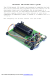
The development system board includes a transmitter which can be used to test the receiver portion of
the system if other external transmitters or signal generators are not available. The on-board
transmitter’s frequency, modulation and baud rate are all set to match the default configuration of the
receiver as shipped from the factory.
11