1
Bright Cluster Manager 7.1
Installation Manual
Revision: 6825
Date: Thu, 10 Dec 2015
©2015 Bright Computing, Inc. All Rights Reserved. This manual or parts thereof may not be reproduced
in any form unless permitted by contract or by written permission of Bright Computing, Inc.
Trademarks
Linux is a registered trademark of Linus Torvalds. PathScale is a registered trademark of Cray, Inc. Red
Hat and all Red Hat-based trademarks are trademarks or registered trademarks of Red Hat, Inc. SUSE
is a registered trademark of Novell, Inc. PGI is a registered trademark of NVIDIA Corporation. FLEXlm
is a registered trademark of Flexera Software, Inc. ScaleMP is a registered trademark of ScaleMP, Inc.
All other trademarks are the property of their respective owners.
Rights and Restrictions
All statements, specifications, recommendations, and technical information contained herein are current
or planned as of the date of publication of this document. They are reliable as of the time of this writing
and are presented without warranty of any kind, expressed or implied. Bright Computing, Inc. shall
not be liable for technical or editorial errors or omissions which may occur in this document. Bright
Computing, Inc. shall not be liable for any damages resulting from the use of this document.
Limitation of Liability and Damages Pertaining to Bright Computing, Inc.
The Bright Cluster Manager product principally consists of free software that is licensed by the Linux
authors free of charge. Bright Computing, Inc. shall have no liability nor will Bright Computing, Inc.
provide any warranty for the Bright Cluster Manager to the extent that is permitted by law. Unless
confirmed in writing, the Linux authors and/or third parties provide the program as is without any
warranty, either expressed or implied, including, but not limited to, marketability or suitability for a
specific purpose. The user of the Bright Cluster Manager product shall accept the full risk for the quality or performance of the product. Should the product malfunction, the costs for repair, service, or
correction will be borne by the user of the Bright Cluster Manager product. No copyright owner or
third party who has modified or distributed the program as permitted in this license shall be held liable
for damages, including general or specific damages, damages caused by side effects or consequential
damages, resulting from the use of the program or the un-usability of the program (including, but not
limited to, loss of data, incorrect processing of data, losses that must be borne by you or others, or the
inability of the program to work together with any other program), even if a copyright owner or third
party had been advised about the possibility of such damages unless such copyright owner or third
party has signed a writing to the contrary.
Table of Contents
Table of Contents . . . . . . . . . . . . . . . . . . . . . . . . . . . . . . . . . . . . . . . . . . . . .
i
Quickstart Installation Guide
1.1 Installing The Head Node . . . . .
1.2 First Boot . . . . . . . . . . . . . . .
1.3 Booting Regular Nodes . . . . . . .
1.4 Optional: Upgrading Python . . .
1.5 Running Cluster Management GUI
.
.
.
.
.
1
1
4
5
6
6
2
Introduction
2.1 What Is Bright Cluster Manager? . . . . . . . . . . . . . . . . . . . . . . . . . . . . . . . . .
2.2 Cluster Structure . . . . . . . . . . . . . . . . . . . . . . . . . . . . . . . . . . . . . . . . . .
9
9
9
3
Installing Bright Cluster Manager
3.1 Minimal Hardware Requirements . . . . . . .
3.1.1 Head Node . . . . . . . . . . . . . . .
3.1.2 Compute Nodes . . . . . . . . . . . .
3.2 Supported Hardware . . . . . . . . . . . . . .
3.2.1 Compute Nodes . . . . . . . . . . . .
3.2.2 Ethernet Switches . . . . . . . . . . . .
3.2.3 Power Distribution Units . . . . . . .
3.2.4 Management Controllers . . . . . . .
3.2.5 InfiniBand . . . . . . . . . . . . . . . .
3.2.6 GPUs . . . . . . . . . . . . . . . . . . .
3.2.7 MICs . . . . . . . . . . . . . . . . . . .
3.3 Head Node Installation: Bare Metal Method .
3.3.1 Welcome Screen . . . . . . . . . . . . .
3.3.2 Software License . . . . . . . . . . . .
3.3.3 Kernel Modules Configuration . . . .
3.3.4 Hardware Overview . . . . . . . . . .
3.3.5 Nodes Configuration . . . . . . . . . .
3.3.6 Network Topology . . . . . . . . . . .
3.3.7 Additional Network Configuration .
3.3.8 Networks Configuration . . . . . . . .
3.3.9 Nameservers And Search Domains . .
3.3.10 Network Interfaces Configuration . .
3.3.11 Select Subnet Managers . . . . . . . .
3.3.12 Select CD/DVD ROM . . . . . . . . .
3.3.13 Workload Management Configuration
3.3.14 Hadoop . . . . . . . . . . . . . . . . .
3.3.15 OpenStack . . . . . . . . . . . . . . . .
1
.
.
.
.
.
.
.
.
.
.
.
.
.
.
.
.
.
.
.
.
.
.
.
.
.
.
.
.
.
.
.
.
.
.
.
.
.
.
.
.
.
.
.
.
.
.
.
.
.
.
.
.
.
.
.
.
.
.
.
.
.
.
.
.
.
.
.
.
.
.
.
.
.
.
.
.
.
.
.
.
.
.
.
.
.
.
.
.
.
.
.
.
.
.
.
.
.
.
.
.
.
.
.
.
.
.
.
.
.
.
.
.
.
.
.
.
.
.
.
.
.
.
.
.
.
.
.
.
.
.
.
.
.
.
.
.
.
.
.
.
.
.
.
.
.
.
.
.
.
.
.
.
.
.
.
.
.
.
.
.
.
.
.
.
.
.
.
.
.
.
.
.
.
.
.
.
.
.
.
.
.
.
.
.
.
.
.
.
.
.
.
.
.
.
.
.
.
.
.
.
.
.
.
.
.
.
.
.
.
.
.
.
.
.
.
.
.
.
.
.
.
.
.
.
.
.
.
.
.
.
.
.
.
.
.
.
.
.
.
.
.
.
.
.
.
.
.
.
.
.
.
.
.
.
.
.
.
.
.
.
.
.
.
.
.
.
.
.
.
.
.
.
.
.
.
.
.
.
.
.
.
.
.
.
.
.
.
.
.
.
.
.
.
.
.
.
.
.
.
.
.
.
.
.
.
.
.
.
.
.
.
.
.
.
.
.
.
.
.
.
.
.
.
.
.
.
.
.
.
.
.
.
.
.
.
.
.
.
.
.
.
.
.
.
.
.
.
.
.
.
.
.
.
.
.
.
.
.
.
.
.
.
.
.
.
.
.
.
.
.
.
.
.
.
.
.
.
.
.
.
.
.
.
.
.
.
.
.
.
.
.
.
.
.
.
.
.
.
.
.
.
.
.
.
.
.
.
.
.
.
.
.
.
.
.
.
.
.
.
.
.
.
.
.
.
.
.
.
.
.
.
.
.
.
.
.
.
.
.
.
.
.
.
.
.
.
.
.
.
.
.
.
.
.
.
.
.
.
.
.
.
.
.
.
.
.
.
.
.
.
.
.
.
.
.
.
.
.
.
.
.
.
.
.
.
.
.
.
.
.
.
.
.
.
.
.
.
.
.
.
.
.
.
.
.
.
.
.
.
.
.
.
.
.
.
.
.
.
.
.
.
.
.
.
.
.
.
.
.
.
.
.
.
.
.
.
.
.
.
.
.
.
.
.
.
.
.
.
.
.
.
.
.
.
.
.
.
.
.
.
.
.
.
.
.
.
.
.
.
.
.
.
.
.
.
.
.
.
.
.
.
.
.
.
.
.
.
.
.
.
.
.
.
.
.
.
.
.
.
.
.
.
.
.
.
.
.
.
.
.
.
.
.
.
.
.
.
.
.
.
.
.
.
.
.
.
.
.
.
.
.
.
.
.
.
.
.
.
.
.
.
.
.
.
.
.
.
.
.
.
.
.
.
.
.
.
.
.
.
.
.
.
.
.
.
.
.
.
.
.
.
.
.
.
.
.
.
.
.
.
.
.
.
.
.
.
.
.
.
.
.
.
.
.
.
.
.
.
.
.
.
.
.
.
.
.
.
.
.
.
.
.
.
.
.
.
.
.
.
.
.
.
.
.
.
.
.
.
.
.
.
.
.
.
.
.
.
.
.
.
.
.
.
.
.
.
.
.
.
.
.
.
.
.
.
.
.
.
.
.
.
.
.
.
.
.
.
.
.
.
.
.
.
.
.
.
.
.
.
.
.
.
.
.
.
.
.
.
.
.
.
.
.
.
.
.
.
.
.
.
.
.
.
.
.
.
.
.
.
.
.
.
.
.
.
.
.
.
.
.
.
.
.
.
.
.
.
.
.
.
.
.
.
.
.
.
.
.
.
.
.
.
.
.
.
.
.
.
.
.
.
.
.
.
.
.
.
11
11
11
11
12
12
12
12
12
12
13
13
13
13
14
16
18
19
20
23
26
27
28
31
31
32
33
34
ii
Table of Contents
.
.
.
.
.
.
.
.
.
.
.
.
.
36
36
38
39
40
41
42
43
45
45
46
46
46
Licensing Bright Cluster Manager
4.1 Displaying License Attributes . . . . . . . . . . . . . . . . . . . . . . . . . . . . . . . . . . .
4.2 Verifying A License—The verify-license Utility . . . . . . . . . . . . . . . . . . . . . .
4.2.1 The verify-license Utility Can Be Used When licenseinfo Cannot Be Used
4.2.2 Using The verify-license Utility To Troubleshoot License Issues . . . . . . . .
4.3 Requesting And Installing A License Using A Product Key . . . . . . . . . . . . . . . . . .
4.3.1 Is A License Needed?—Verifying License Attributes . . . . . . . . . . . . . . . . . .
4.3.2 The Product Key . . . . . . . . . . . . . . . . . . . . . . . . . . . . . . . . . . . . . .
4.3.3 Requesting A License With The request-license Script . . . . . . . . . . . . . .
4.3.4 Installing A License With The install-license Script . . . . . . . . . . . . . . .
4.3.5 Re-Installing A License For Upgrading From Single Head To High-Availability
Configuration . . . . . . . . . . . . . . . . . . . . . . . . . . . . . . . . . . . . . . . .
4.3.6 Re-Installing A License After Replacing The Hardware . . . . . . . . . . . . . . . .
4.3.7 Re-Installing A License After Wiping Or Replacing The Hard Drive . . . . . . . . .
4.3.8 Rebooting Nodes After An Install . . . . . . . . . . . . . . . . . . . . . . . . . . . .
53
54
55
55
55
56
56
57
57
59
60
60
61
61
Linux Distributions That Use Registration
5.1 Registering A Red Hat Enterprise Linux Based Cluster . .
5.1.1 Registering A Head Node With RHEL . . . . . . . .
5.1.2 Registering A Software Image With RHEL . . . . .
5.2 Registering A SUSE Linux Enterprise Server Based Cluster
5.2.1 Registering A Head Node With SUSE . . . . . . . .
5.2.2 Registering A Software Image With SUSE . . . . . .
.
.
.
.
.
.
63
63
63
64
65
66
66
6
Changing The Network Parameters Of The Head Node
6.1 Introduction . . . . . . . . . . . . . . . . . . . . . . . . . . . . . . . . . . . . . . . . . . . . .
6.2 Method . . . . . . . . . . . . . . . . . . . . . . . . . . . . . . . . . . . . . . . . . . . . . . . .
6.3 Terminology . . . . . . . . . . . . . . . . . . . . . . . . . . . . . . . . . . . . . . . . . . . . .
69
69
69
69
7
Third Party Software
7.1 Modules Environment . . . . . . . . . . . . . . . . . . . . . . . . . . . . . . . . . . . . . . .
7.2 Shorewall . . . . . . . . . . . . . . . . . . . . . . . . . . . . . . . . . . . . . . . . . . . . . . .
7.2.1 The Shorewall Service Paradigm . . . . . . . . . . . . . . . . . . . . . . . . . . . . .
73
73
73
73
3.4
4
5
3.3.16 Ceph . . . . . . . . . . . . . . . . . . .
3.3.17 Disk Partitioning And Layouts . . . .
3.3.18 Time Configuration . . . . . . . . . . .
3.3.19 Cluster Access . . . . . . . . . . . . . .
3.3.20 Authentication . . . . . . . . . . . . .
3.3.21 Console . . . . . . . . . . . . . . . . .
3.3.22 Summary . . . . . . . . . . . . . . . .
3.3.23 Installation . . . . . . . . . . . . . . . .
3.3.24 Licensing And Further Configuration
Head Node Installation: Add-On Method . .
3.4.1 Prerequisites . . . . . . . . . . . . . . .
3.4.2 Installing The Installer . . . . . . . . .
3.4.3 Running The Installer . . . . . . . . .
.
.
.
.
.
.
.
.
.
.
.
.
.
.
.
.
.
.
.
.
.
.
.
.
.
.
.
.
.
.
.
.
.
.
.
.
.
.
.
.
.
.
.
.
.
.
.
.
.
.
.
.
.
.
.
.
.
.
.
.
.
.
.
.
.
.
.
.
.
.
.
.
.
.
.
.
.
.
.
.
.
.
.
.
.
.
.
.
.
.
.
.
.
.
.
.
.
.
.
.
.
.
.
.
.
.
.
.
.
.
.
.
.
.
.
.
.
.
.
.
.
.
.
.
.
.
.
.
.
.
.
.
.
.
.
.
.
.
.
.
.
.
.
.
.
.
.
.
.
.
.
.
.
.
.
.
.
.
.
.
.
.
.
.
.
.
.
.
.
.
.
.
.
.
.
.
.
.
.
.
.
.
.
.
.
.
.
.
.
.
.
.
.
.
.
.
.
.
.
.
.
.
.
.
.
.
.
.
.
.
.
.
.
.
.
.
.
.
.
.
.
.
.
.
.
.
.
.
.
.
.
.
.
.
.
.
.
.
.
.
.
.
.
.
.
.
.
.
.
.
.
.
.
.
.
.
.
.
.
.
.
.
.
.
.
.
.
.
.
.
.
.
.
.
.
.
.
.
.
.
.
.
.
.
.
.
.
.
.
.
.
.
.
.
.
.
.
.
.
.
.
.
.
.
.
.
.
.
.
.
.
.
.
.
.
.
.
.
.
.
.
.
.
.
.
.
.
.
.
.
.
.
.
.
.
.
.
.
.
.
.
.
.
.
.
.
.
.
.
.
.
.
.
.
.
.
.
.
.
.
.
.
.
.
.
.
.
.
.
.
.
.
.
.
.
.
.
.
.
.
.
.
.
.
.
.
.
.
.
.
.
.
.
.
.
.
.
.
.
.
.
.
.
.
.
.
.
.
.
.
.
.
.
.
.
.
.
.
.
.
.
.
.
.
.
.
.
Table of Contents
7.2.2
7.2.3
7.3
7.4
7.5
7.6
7.7
7.8
7.9
Shorewall Zones, Policies, And Rules . . . . . . . . . . . . . . . . . . . . . . . . . .
Clear And Stop Behavior In service Options, bash Shell Command, And cmsh
Shell . . . . . . . . . . . . . . . . . . . . . . . . . . . . . . . . . . . . . . . . . . . . .
7.2.4 Further Shorewall Quirks . . . . . . . . . . . . . . . . . . . . . . . . . . . . . . . . .
Compilers . . . . . . . . . . . . . . . . . . . . . . . . . . . . . . . . . . . . . . . . . . . . . .
7.3.1 GCC . . . . . . . . . . . . . . . . . . . . . . . . . . . . . . . . . . . . . . . . . . . . .
7.3.2 Intel Compiler Suite . . . . . . . . . . . . . . . . . . . . . . . . . . . . . . . . . . . .
7.3.3 PGI High-Performance Compilers . . . . . . . . . . . . . . . . . . . . . . . . . . . .
7.3.4 AMD Open64 Compiler Suite . . . . . . . . . . . . . . . . . . . . . . . . . . . . . . .
7.3.5 FLEXlm License Daemon . . . . . . . . . . . . . . . . . . . . . . . . . . . . . . . . .
Intel Cluster Checker . . . . . . . . . . . . . . . . . . . . . . . . . . . . . . . . . . . . . . . .
7.4.1 Package Installation . . . . . . . . . . . . . . . . . . . . . . . . . . . . . . . . . . . .
7.4.2 Preparing Configuration And Node List Files . . . . . . . . . . . . . . . . . . . . .
7.4.3 Running Intel Cluster Checker . . . . . . . . . . . . . . . . . . . . . . . . . . . . . .
7.4.4 Applying For The Certificate . . . . . . . . . . . . . . . . . . . . . . . . . . . . . . .
CUDA For GPUs . . . . . . . . . . . . . . . . . . . . . . . . . . . . . . . . . . . . . . . . . .
7.5.1 Installing CUDA . . . . . . . . . . . . . . . . . . . . . . . . . . . . . . . . . . . . . .
7.5.2 Installing Kernel Development Packages . . . . . . . . . . . . . . . . . . . . . . . .
7.5.3 Verifying CUDA . . . . . . . . . . . . . . . . . . . . . . . . . . . . . . . . . . . . . .
7.5.4 Verifying OpenCL . . . . . . . . . . . . . . . . . . . . . . . . . . . . . . . . . . . . .
7.5.5 Configuring The X server . . . . . . . . . . . . . . . . . . . . . . . . . . . . . . . . .
OFED Software Stack . . . . . . . . . . . . . . . . . . . . . . . . . . . . . . . . . . . . . . . .
7.6.1 Choosing A Distribution Version Or Bright Cluster Manager Version, Ensuring
The Kernel Matches, And Logging The Installation . . . . . . . . . . . . . . . . . .
7.6.2 Mellanox and QLogic (Intel True Scale) OFED Stack Installation Using The Bright
Computing Repository . . . . . . . . . . . . . . . . . . . . . . . . . . . . . . . . . . .
Lustre . . . . . . . . . . . . . . . . . . . . . . . . . . . . . . . . . . . . . . . . . . . . . . . . .
7.7.1 Architecture . . . . . . . . . . . . . . . . . . . . . . . . . . . . . . . . . . . . . . . . .
7.7.2 Preparation . . . . . . . . . . . . . . . . . . . . . . . . . . . . . . . . . . . . . . . . .
7.7.3 Server Implementation . . . . . . . . . . . . . . . . . . . . . . . . . . . . . . . . . . .
7.7.4 Client Implementation . . . . . . . . . . . . . . . . . . . . . . . . . . . . . . . . . . .
Intel Enterprise Edition For Lustre (IEEL) . . . . . . . . . . . . . . . . . . . . . . . . . . . .
7.8.1 Introduction . . . . . . . . . . . . . . . . . . . . . . . . . . . . . . . . . . . . . . . . .
7.8.2 Installing Intel Manager For Lustre (IML) . . . . . . . . . . . . . . . . . . . . . . . .
7.8.3 Creating Software Images For Lustre Server Nodes . . . . . . . . . . . . . . . . . .
7.8.4 Creating Categories For Lustre Server Nodes . . . . . . . . . . . . . . . . . . . . . .
7.8.5 Creating Software Images For Lustre Client Nodes . . . . . . . . . . . . . . . . . .
7.8.6 Configuration Using The Dashboard Of Intel Manager For Lustre . . . . . . . . . .
7.8.7 IEEL information in cmgui . . . . . . . . . . . . . . . . . . . . . . . . . . . . . . . .
ScaleMP . . . . . . . . . . . . . . . . . . . . . . . . . . . . . . . . . . . . . . . . . . . . . . .
7.9.1 Installing vSMP For Cloud . . . . . . . . . . . . . . . . . . . . . . . . . . . . . . . .
7.9.2 Creating Virtual SMP Nodes . . . . . . . . . . . . . . . . . . . . . . . . . . . . . . .
7.9.3 Virtual SMP Node Settings . . . . . . . . . . . . . . . . . . . . . . . . . . . . . . . .
iii
74
74
74
75
75
75
77
77
78
78
78
79
81
82
82
82
84
84
86
87
88
88
88
91
91
92
92
96
97
97
98
100
103
107
110
112
115
116
116
117
iv
8
9
Table of Contents
Burning Nodes
8.1 Test Scripts Deployment . . . . . . . . . . . . . . . . .
8.2 Burn Configurations . . . . . . . . . . . . . . . . . . .
8.2.1 Mail Tag . . . . . . . . . . . . . . . . . . . . . .
8.2.2 Pre-install And Post-install . . . . . . . . . . .
8.2.3 Post-burn Install Mode . . . . . . . . . . . . . .
8.2.4 Phases . . . . . . . . . . . . . . . . . . . . . . .
8.2.5 Tests . . . . . . . . . . . . . . . . . . . . . . . .
8.3 Running A Burn Configuration . . . . . . . . . . . . .
8.3.1 Burn Configuration And Execution In cmgui .
8.3.2 Burn Configuration And Execution In cmsh .
8.3.3 Writing A Test Script . . . . . . . . . . . . . . .
8.3.4 Burn Failures . . . . . . . . . . . . . . . . . . .
8.4 Relocating The Burn Logs . . . . . . . . . . . . . . . .
8.4.1 Configuring The Relocation . . . . . . . . . . .
8.4.2 Testing The Relocation . . . . . . . . . . . . . .
.
.
.
.
.
.
.
.
.
.
.
.
.
.
.
.
.
.
.
.
.
.
.
.
.
.
.
.
.
.
.
.
.
.
.
.
.
.
.
.
.
.
.
.
.
.
.
.
.
.
.
.
.
.
.
.
.
.
.
.
.
.
.
.
.
.
.
.
.
.
.
.
.
.
.
.
.
.
.
.
.
.
.
.
.
.
.
.
.
.
.
.
.
.
.
.
.
.
.
.
.
.
.
.
.
.
.
.
.
.
.
.
.
.
.
.
.
.
.
.
.
.
.
.
.
.
.
.
.
.
.
.
.
.
.
.
.
.
.
.
.
.
.
.
.
.
.
.
.
.
.
.
.
.
.
.
.
.
.
.
.
.
.
.
.
.
.
.
.
.
.
.
.
.
.
.
.
.
.
.
.
.
.
.
.
.
.
.
.
.
.
.
.
.
.
.
.
.
.
.
.
.
.
.
.
.
.
.
.
.
.
.
.
.
.
.
.
.
.
.
.
.
.
.
.
.
.
.
.
.
.
.
.
.
.
.
.
.
.
.
.
.
.
.
.
.
.
.
.
.
.
.
.
.
.
.
.
.
.
.
.
.
.
.
.
.
.
.
.
.
.
.
.
.
.
.
.
.
.
.
.
.
.
.
.
.
.
.
.
.
.
.
.
.
.
.
.
.
.
.
119
119
119
120
120
120
120
120
121
121
122
127
130
131
131
132
Installing And Configuring SELinux
9.1 Introduction . . . . . . . . . . . . . . . . . . . . . . . . . .
9.2 Enabling SELinux On SLES11SP2 Systems . . . . . . . . .
9.2.1 Regular Nodes . . . . . . . . . . . . . . . . . . . .
9.2.2 Head Node . . . . . . . . . . . . . . . . . . . . . .
9.3 Enabling SELinux on RHEL6 . . . . . . . . . . . . . . . .
9.3.1 Regular Nodes . . . . . . . . . . . . . . . . . . . .
9.3.2 Head Node . . . . . . . . . . . . . . . . . . . . . .
9.4 Additional Considerations . . . . . . . . . . . . . . . . . .
9.4.1 Provisioning The .autorelabel File Tag . . . .
9.4.2 SELinux Warnings During Regular Node Updates
9.5 Filesystem Security Context Checks . . . . . . . . . . . .
.
.
.
.
.
.
.
.
.
.
.
.
.
.
.
.
.
.
.
.
.
.
.
.
.
.
.
.
.
.
.
.
.
.
.
.
.
.
.
.
.
.
.
.
.
.
.
.
.
.
.
.
.
.
.
.
.
.
.
.
.
.
.
.
.
.
.
.
.
.
.
.
.
.
.
.
.
.
.
.
.
.
.
.
.
.
.
.
.
.
.
.
.
.
.
.
.
.
.
.
.
.
.
.
.
.
.
.
.
.
.
.
.
.
.
.
.
.
.
.
.
.
.
.
.
.
.
.
.
.
.
.
.
.
.
.
.
.
.
.
.
.
.
.
.
.
.
.
.
.
.
.
.
.
.
.
.
.
.
.
.
.
.
.
.
.
.
.
.
.
.
.
.
.
.
.
.
.
.
.
.
.
.
.
.
.
.
.
.
.
.
.
.
.
.
.
.
.
.
.
.
.
.
.
.
.
.
.
.
135
135
135
135
137
137
137
137
138
138
138
138
.
.
.
.
.
.
.
.
.
.
.
.
.
.
.
1
Quickstart Installation Guide
This chapter describes a basic and quick installation of Bright Cluster Manager on “bare metal” cluster hardware as a step-by-step process, and gives very little explanation of the steps. Following these
steps should allow a moderately experienced cluster administrator to get a cluster up and running in
a fairly standard configuration as quickly as possible. This would be without even having to read the
introductory Chapter 2 of this manual, let alone the entire manual. References to chapters and sections
are provided where appropriate.
Some asides, before getting on with the steps themselves:
• If the cluster has already been installed, tested, and configured, but only needs to be configured
now for a new network, then the administrator should only need to look at Chapter 6. Chapter 6
lays out how to carry out the most common configuration changes that usually need to be done to
make the cluster work in the new network.
• For administrators that are very unfamiliar with clusters, reading the introduction (Chapter 2)
and then the more detailed installation walkthrough for a bare metal installation (Chapter 3, sections 3.1, 3.2, and 3.3) is recommended. Having carried out the head node installation, the administrator can then return to this quickstart chapter (Chapter 1), and continue onward with the
quickstart process of regular node installation (section 1.3).
• The configuration and administration of the cluster after it has been installed is covered in the
Bright Cluster Manager Administrator Manual. The Administrator Manual should be consulted for
further background information as well as guidance on cluster administration tasks, after the introduction (Chapter 2) of the Installation Manual has been read.
• If all else fails, administrator-level support is available via https://support.
brightcomputing.com. Section 10.2 of the Administrator Manual has further details on
how to brief the support team, so that the issue can be resolved as quickly as possible.
The quickstart steps now follow:
1.1
Installing The Head Node
The head node does not need to be connected to the regular nodes at this point, though it helps to have
the wiring done beforehand so that how things are connected is known.
1. The BIOS of the head node should have the local time set.
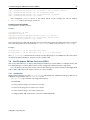
2. The head node should be booted from the Bright Cluster Manager DVD.
3. The option: Install Bright Cluster Manager should be selected in the text boot menu.
This brings up the GUI installation Welcome screen.
© Bright Computing, Inc.
2
Quickstart Installation Guide
4. At the Welcome screen, Continue should be clicked. By default, this continues with a Normal
(recommended) installation mode.
5. At the License screens:
• At the Bright Computing Software License screen, the acceptance checkbox should
be ticked. Continue should then be ticked.
• At the Linux base distribution screen, the acceptance checkbox should be ticked. Continue
should then be clicked.
6. At the Kernel Modules screen, Continue should be clicked.
7. At the Hardware Information screen, the detected hardware should be reviewed. If additional
kernel modules are required, then the administrator should go back to the Kernel Modules
screen. Once all the relevant hardware (Ethernet interfaces, hard drive and DVD drive) is detected,
Continue should be clicked.
8. At the Nodes screen:
• The number of racks and regular nodes are specified
• The base name for the regular nodes is set. Accepting the default of node means nodes names
are prefixed with node, for example: node001, node002...
• The number of digits to append to the base name is set. For example, accepting the default of
3 means nodes from node001 to node999 are possible names.
• The correct hardware manufacturer is selected
Continue is then clicked.
9. At the Network Topology screen, a network layout is chosen. The default layout, private
internal network, is the most commonly used layout. The rest of this chapter assumes the
default layout was chosen. Click Continue
10. At the Additional Network Configuration screen, it is possible to:
• add an InfiniBand and/or 10 Gig-E network, and
• configure the use of IPMI/iLO BMCs on the nodes. Adding an IPMI/iLO network is needed
to configure IPMI/iLO interfaces in a different IP subnet, and is recommended.
When done, Continue should be clicked.
11. At the Networks screen, the network parameters for the head node should be entered for the
interface facing the network named externalnet:
• If using DHCP on that interface, the OK button should be clicked to accept the parameters
for IP Address, Netmask and Gateway as suggested by the DHCP server on the external
network.
• If not using DHCP on that interface, the Use DHCP checkbox should be unchecked, and static
values put in instead. Then the OK button should be clicked.
The network parameters for externalnet can then then be reviewed. These are the:
• base address (also called the network address)
• netmask
• domain name
© Bright Computing, Inc.
1.1 Installing The Head Node
3
• default gateway
The network externalnet corresponds to the site network that the cluster resides in (for example, a corporate or campus network). The IP address details are therefore the details of the head
node for a type 1 externalnet network (figure 3.8). A domain name should be entered to suit the
local requirements.
12. At the Nameservers screen, additional DNS search domains and additional external DNS name
servers, if required, can be added or removed. For the default network topology (see item 9,
page 2), if the external network has a DHCP lease with DNS configuration information, then nothing needs to be added to resolve external hosts. Continue should be clicked.
13. At the Network Interfaces screen:
• The IP addresses assigned to the network interfaces should be reviewed. All networks besides the externalnet network use private IP ranges by default and normally do not have
to be changed.
• If necessary, the node interface properties should be modified. When IPMI/iLO interfaces
reside in the same IP subnet, an IP Offset is set for the ipmi0 interface.
Continue should be clicked.
14. The Subnet Managers screen is displayed if an InfiniBand network was enabled. At this screen,
nodes (if any) that are to run the subnet manager for the InfiniBand network should be selected.
Continue should then be clicked.
15. At the Installation sources screen, the DVD drive containing the Bright Cluster Manager
DVD should be selected, then Continue clicked.
16. At the Workload Management screen, a workload manager should be selected and the number
of slots per node set to be equal to the number of CPU cores per node. Continue should then be
clicked.
17. At the Disk Partitioning and Layouts screen, a drive should be selected on the head node.
The installation will be done onto this drive, overwriting all its previous content.
The administrator can modify the disk layout for the head node by selecting a pre-defined layout.
For hard drives that have less than about
master-one-big-partition.xml is used by default:
500GB
space,
Partition
Space
Mounted At
Filesystem Type
1
512M
/boot
ext2
2
16G
-
swap
3
rest
/
ext3
the
XML
file
Default layout for up to 500GB: One big partition.
For hard drives that have about 500GB or more of space, the XML file master-standard.xml is
used by default:
© Bright Computing, Inc.
4
Quickstart Installation Guide
Partition
Space
Mounted At
Filesystem Type
1
512M
/boot
ext2
2
16G
-
swap
3
8G
/tmp
ext3
4
16G
/var
ext3
5
10G
/var/lib/mysql/cmdaemon_mon
ext3
6
rest
/
ext3
Default layout for more than 500GB: Several partitions.
The layouts indicated by these tables may be fine-tuned by editing the XML partitioning definition
during this stage. The “max” setting in the XML file corresponds to the “rest” entry in these tables,
and means the rest of the drive space is used up for the associated partition, whatever the leftover
space is.
There are also other layout templates available from a menu.
Continue is clicked, and then the administrator must confirm that the data on the listed drive(s)
may be erased by clicking Yes.
18. At the Time Configuration screen, a time-zone should be selected, and optionally, NTP timeservers should be added. Continue should be clicked.
19. At the Cluster Access screen, some network restrictions can be set. By default there are no
network-specific restrictions on access to the cluster (e.g. using ssh or cmgui). To accept the
defaults, Continue should be clicked.
20. At the Authentication screen, a hostname should be entered for the head node. Also a password should be entered, twice, for use in system administration. Continue should then be
clicked.
21. At the Console screen, a text or graphical console can be configured for the nodes in the cluster.
It should be noted that the Cluster Management GUI can still be used remotely even if the console
of the head node is set to text mode. Continue should then be clicked.
22. At the Summary screen, the network summary should be reviewed. The Start button then starts
the installation. Yes should be clicked to confirm that the data on the listed drive(s) may be erased.
23. The Installation Progress screen should eventually complete. Clicking on Reboot and
then clicking Yes to confirm, reboots the head node.
1.2
First Boot
1. The DVD should be removed or the boot-order altered in the BIOS to ensure that the head node
boots from the first hard drive.
2. Once the machine is fully booted, a log in should be done as root with the password that was
entered during installation.
3. A check should be done to confirm that the machine is visible on the external network. Also, it
should be checked that the second NIC (i.e. eth1) is physically connected to the external network.
4. If the parent distribution for Bright Cluster Manager is RHEL and SUSE then registration (Chapter 5) should usually be done.
© Bright Computing, Inc.
1.3 Booting Regular Nodes
5
5. The license parameters should be verified to be correct:
cmsh -c "main licenseinfo"
If the license being used is a temporary license (see End Time value), a new license should be
requested well before the temporary license expires. The procedure for requesting and installing
a new license is described in Chapter 4.
1.3
Booting Regular Nodes
1. A check should be done to make sure the first NIC (i.e. eth0) on the head node is physically
connected to the internal cluster network.
2. The BIOS of regular nodes should be configured to boot from the network. The regular nodes
should then be booted. No operating system is expected to be on the regular nodes already. If
there is an operating system there already, then by default, it is overwritten by a default image
provided by the head node during the next stages.
3. If everything goes well, the node-installer component starts on each regular node and a certificate
request is sent to the head node.
If a regular node does not make it to the node-installer stage, then it is possible that additional
kernel modules are needed. Section 5.8 of the Administrator Manual contains more information on
how to diagnose problems during the regular node booting process.
4. To identify the regular nodes (that is, to assign a host name to each physical node), several options
are available. Which option is most convenient depends mostly on the number of regular nodes
and whether a (configured) managed Ethernet switch is present.
Rather than identifying nodes based on their MAC address, it is often beneficial (especially in
larger clusters) to identify nodes based on the Ethernet switch port that they are connected to. To
allow nodes to be identified based on Ethernet switch ports, section 3.8 of the Administrator Manual
should be consulted.
Any one of the following methods may be used to assign node identities when all nodes have been
booted:
a. Identifying each node on the node console: To manually identify each node, the “Manually
select node” option is selected for each node. The node is then identified manually by selecting a node-entry from the list, choosing the Accept option. This option is easiest when
there are not many nodes. It requires being able to view the console of each node and keyboard entry to the console.
b. Identifying nodes using cmgui: The Node Identification Wizard (page 173, section 5.4.2
of the Administrator Manual) in cmgui automates the process of assigning identities so that
nodes do not require manual identification on the console.
c. Identifying nodes using cmsh: In cmsh the newnodes command in device mode
(page 168, section 5.4.2 of the Administrator Manual) can be used to assign identities to nodes
from the command line. When called without parameters, the newnodes command can be
used to verify that all nodes have booted into the node-installer and are all waiting to be
assigned an identity.
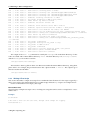
Example
To verify that all regular nodes have booted into the node-installer:
[root@mycluster ~]# cmsh
[mycluster]% device newnodes
MAC
First appeared
© Bright Computing, Inc.
Detected on switch port
6
Quickstart Installation Guide
----------------- ------------------------ ----------------------00:0C:29:D2:68:8D 05 Sep 2011 13:43:13 PDT [no port detected]
00:0C:29:54:F5:94 05 Sep 2011 13:49:41 PDT [no port detected]
..
[mycluster]% device newnodes | wc -l
MAC
First appeared
Detected on switch port
----------------- ------------------- ----------------------32
[mycluster]% exit
[root@mycluster ~]#
Example
Once all regular nodes have been booted in the proper order, the order of their appearance
on the network can be used to assign node identities. To assign identities node001 through
node032 to the first 32 nodes that were booted, the following commands may be used:
[root@mycluster ~]# cmsh
[mycluster]% device newnodes -s -n node001..node032
MAC
First appeared
Hostname
----------------- ----------------------------- --------00:0C:29:D2:68:8D Mon, 05 Sep 2011 13:43:13 PDT node001
00:0C:29:54:F5:94 Mon, 05 Sep 2011 13:49:41 PDT node002
..
[mycluster]% exit
[root@mycluster ~]#
5. Each regular node is now provisioned and eventually fully boots. In case of problems, section 5.8
of the Administrator Manual should be consulted.
6. Optional: To configure power management, Chapter 4 of the Administrator Manual should be consulted.
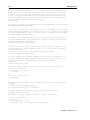
1.4
Optional: Upgrading Python
The version of Python provided by the Linux-based OS distributors typically lags significantly behind
the latest upstream version. This is normally a good thing, since the distributors provide integration,
and carry out testing to make sure it works well with the rest of the OS. It is also the version upon which
Bright Cluster Manager tools depend upon. However, some administrators would like to have the latest
Python versions available on their cluster, for the OS, or for the applications. One reason may be that
later versions have some nicer features.
Installing Python outside of the distribution will normally break Bright Cluster Manager and is therefore not recommended. For administrators that would like to carry out this out-of-distribution upgrade
anyway, there are knowledge base articles #1226 (http://kb.brightcomputing.com/faq/index.
php?action=artikel&cat=23&id=226) and #1197 (http://kb.brightcomputing.com/faq/
index.php?action=artikel&cat=18&id=198) that explain how to do it. If the change is carried
out correctly, then support is not available for Python-related bugs, but is available for the Bright Cluster
Manager-related features.
1.5
Running Cluster Management GUI
To run the Cluster Management GUI (cmgui) on the cluster from a workstation running X11:
1. From a Linux desktop PC, the cmgui user, typically root, should log in to the cluster with SSH
X-forwarding:
ssh -X root@mycluster
© Bright Computing, Inc.
1.5 Running Cluster Management GUI
7
2. the Cluster Management GUI is then started:
cmgui
3. The connect button is clicked (figure 2.2 of the Administrator Manual) and the password that was
configured during installation is entered.
4. Optional: For more information on how the Cluster Management GUI can be used to manage one
or more clusters, section 2.4 of the Administrator Manual can be consulted.
To run the Cluster Management GUI on a desktop PC:
1. The appropriate package(s) for MS Windows, Linux, or Mac OS should be copied from /cm/
shared/apps/cmgui/dist to the desktop PC:
scp root@mycluster:/cm/shared/apps/cmgui/dist/* /tmp
On MS windows WinSCP can be used.
2. The package is installed.
On Windows: the installer is executed and the steps are followed.
On Linux: the contents are extracted using tar -xvjf filename.
On Mac OS: the installer is executed and the steps are followed.
3. The cluster management GUI is started
On Windows: from the Start menu or by clicking the desktop icon.
On Linux: by changing into the cmgui directory and executing:
./cmgui
On Mac OS: from the Start menu or by clicking the desktop icon.
4. Add a new cluster should be clicked on, and the following parameters entered:
Host: Hostname or IP address of the cluster
Password: Password entered during installation
5. The connect button should be clicked on (figure 2.2 of the Administrator Manual)
6. Optional: For more information on how the Cluster Management GUI can be used to manage one
or more clusters, section 2.4 of the Administrator Manual can be consulted.
The cluster should now be ready for running compute jobs.
For more information:
• This manual, the Installation Manual, has more details and background on the installation of
the cluster in the next chapters.
• The Administrator Manual describes the general management of the cluster.
• The User Manual describes the user environment and how to submit jobs for the end user
• The Cloudbursting Manual describes how to deploy the cloud capabilities of the cluster.
• The Developer Manual has useful information for developers who would like to program with
Bright Cluster Manager.
• The OpenStack Deployment Manual describes how to deploy OpenStack with Bright Cluster
Manager
• The Hadoop Deployment Manual describes how to deploy Hadoop with Bright Cluster Manager
• The UCS Deployment Manual describes how to deploy the Cisco UCS server with Bright Cluster
Manager.
© Bright Computing, Inc.
2
Introduction
2.1
What Is Bright Cluster Manager?
Bright Cluster Manager 7.1 is a cluster management application built on top of major Linux distributions. It is available for:
• Versions 6 and 7 of
– Scientific Linux
– Red Hat Enterprise Linux Server
– CentOS
• and also
– SUSE Enterprise Server 11sp2, 11sp3
– SUSE Enterprise Server 12
The Bright Cluster Manager application runs within these distributions on the x86_64 architecture
that is supported by Intel and AMD 64-bit CPUs.
In addition to running directly on the distributions listed above, Bright Cluster Manager can be
controlled by these front ends:
• cmgui (section 2.4 of the Administrator Manual): a GUI which conveniently runs on all major Linux
distributions, as well as on the MS Windows and MacOS operating systems
• cmsh (section 2.5 of the Administrator Manual): an interactive shell front end that can be accessed
from any computing device with a secured SSH terminal access
This chapter introduces some features of Bright Cluster Manager and describes a basic cluster in
terms of its hardware.
2.2
Cluster Structure
In its most basic form, a cluster running Bright Cluster Manager contains:
• One machine designated as the head node
• Several machines designated as compute nodes
• One or more (possibly managed) Ethernet switches
• One or more power distribution units (Optional)
© Bright Computing, Inc.
10
Introduction
The head node is the most important machine within a cluster because it controls all other devices,
such as compute nodes, switches and power distribution units. Furthermore, the head node is also the
host that all users (including the administrator) log in to. The head node is typically the only machine
that is connected directly to the external network and is usually the only machine in a cluster that is
equipped with a monitor and keyboard. The head node provides several vital services to the rest of
the cluster, such as central data storage, workload management, user management, DNS and DHCP
service. The head node in a cluster is also frequently referred to as the master node.
Often, the head node is replicated to a second head node, frequently called a passive head node. If
the active head node fails, the passive head node can become active and take over. This is known as a
high availability setup, and is a typical configuration (Chapter 12 of the Administrator Manual) in Bright
Cluster Manager.
A cluster normally contains a considerable number of non-head, or regular nodes, also referred to
simply as nodes. The head node, not surprisingly, manages these regular nodes over the network.
Most of the regular nodes are compute nodes. Compute nodes are the machines that will do the heavy
work when a cluster is being used for large computations. In addition to compute nodes, larger clusters
may have other types of nodes as well (e.g. storage nodes and login nodes). Nodes typically install
automatically through the (network bootable) node provisioning system that is included with Bright
Cluster Manager. Every time a compute node is started, the software installed on its local hard drive
is synchronized automatically against a software image which resides on the head node. This ensures
that a node can always be brought back to a “known state”. The node provisioning system greatly eases
compute node administration and makes it trivial to replace an entire node in the event of hardware
failure. Software changes need to be carried out only once (in the software image), and can easily be
undone. In general, there will rarely be a need to log on to a compute node directly.
In most cases, a cluster has a private internal network, which is usually built from one or multiple
managed Gigabit Ethernet switches, or made up of an InfiniBand fabric. The internal network connects
all nodes to the head node and to each other. Compute nodes use the internal network for booting,
data storage and interprocess communication. In more advanced cluster setups, there may be several
dedicated networks. It should be noted that the external network—which could be a university campus
network, company network or the Internet—is not normally directly connected to the internal network.
Instead, only the head node is connected to the external network.
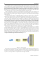
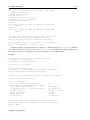
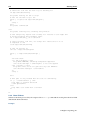
Figure 2.1 illustrates a typical cluster network setup.
Figure 2.1: Cluster network
Most clusters are equipped with one or more power distribution units. These units supply power to
all compute nodes and are also connected to the internal cluster network. The head node in a cluster can
use the power control units to switch compute nodes on or off. From the head node, it is straightforward
to power on/off a large number of compute nodes with a single command.
© Bright Computing, Inc.
3
Installing Bright Cluster
Manager
This chapter describes in detail the installation of Bright Cluster Manager onto the head node of a cluster.
Sections 3.1 and 3.2 list hardware requirements and supported hardware. Section 3.3 gives step-by-step
instructions on installing Bright Cluster Manager from a DVD onto a head node that has no operating
system running on it initially, while section 3.4 gives instructions on installing onto a head node that
already has an operating system running on it.
Once the head node is installed, the other, regular, nodes can (PXE) boot off the head node and provision themselves from it with a default image, without requiring a Linux distribution DVD themselves.
Regular nodes normally have any existing data wiped during the process of provisioning from the head
node, which means that a faulty drive can normally simply be replaced by taking the regular node offline, replacing its drive, and then bringing the node back online, without special reconfiguration. The
details of the PXE boot and provisioning process for the regular nodes are described in Chapter 5 of the
Administrator Manual.
The installation of software on an already-configured cluster running Bright Cluster Manager is described in Chapter 8 of the Administrator Manual.
3.1
Minimal Hardware Requirements
The following are minimal hardware requirements:
3.1.1 Head Node
• Intel Xeon or AMD Opteron CPU (64-bit)
• 2GB RAM
• 80GB diskspace
• 2 Gigabit Ethernet NICs (for the most common Type 1 topology (section 3.3.6))
• DVD drive
3.1.2 Compute Nodes
• Intel Xeon or AMD Opteron CPU (64-bit)
• 1GB RAM (at least 4GB is recommended for diskless nodes)
• 1 Gigabit Ethernet NIC
© Bright Computing, Inc.
12
Installing Bright Cluster Manager
3.2
Supported Hardware
The following hardware is supported:
3.2.1 Compute Nodes
• SuperMicro
• Cray
• Cisco
• Dell
• Fujitsu
• Huawei
• IBM
• Asus
• Hewlett Packard
• Sun
Other brands are also expected to work, even if not explicitly supported.
3.2.2 Ethernet Switches
• HP ProCurve
• Nortel
• Cisco
• Dell
• SuperMicro
• Netgear
Other brands are also expected to work, although not explicitly supported.
3.2.3 Power Distribution Units
• APC (American Power Conversion) Switched Rack PDU
Other brands with the same SNMP MIB mappings are also expected to work, although not explicitly
supported.
3.2.4 Management Controllers
• IPMI 1.5/2.0
• HP iLO 1/2/3
3.2.5 InfiniBand
• Mellanox HCAs, and most other InfiniBand HCAs
• Mellanox, Voltaire, Flextronics InfiniBand switches
• QLogic (Intel True Scale) InfiniBand switches
• Most other InfiniBand switches
© Bright Computing, Inc.
3.3 Head Node Installation: Bare Metal Method
13
3.2.6 GPUs
• NVIDIA Tesla with latest recommended drivers
• NVIDIA GeForce and other older generations are mostly supported. Bright Computing can be
consulted for details.
3.2.7 MICs
• Xeon Phi: All processor versions
3.3
Head Node Installation: Bare Metal Method
A bare metal installation, that is, installing the head node onto a machine with no operating system
on it already, is the recommended option. This is because it cannot run into issues from an existing
configuration. An operating system from one of the ones listed in section 2.1 is installed during a bare
metal installation. The alternative to a bare metal installation is the add-on installation of section 3.4.
Just to be clear, a bare metal installation can be a physical machine with nothing running on it, but
it can also a be virtual machine–such as a VMware, VirtualBox, or KVM instance–with nothing running
on it. Virtual instances may need some additional adjustment to ensure virtualization-related settings
are dealt with correctly. Details on installing Bright Cluster Manager onto virtual instances can be found
in the Bright Cluster Manager Knowledge Base at http://kb.brightcomputing.com.
To start a physical bare metal installation, the time in the BIOS of the head node is set to local time.
The head node is then made to boot from DVD, which can typically be done by appropriate keystrokes
when the head node boots, or via a BIOS configuration.
Booting from the DVD first loads up and presents a pre-installer menu. The pre-installer menu
offers a default option of booting from the hard drive, and has a countdown to deploying that. The
countdown should be interrupted by selecting the option of “Install Bright Cluster Manager”
instead, which starts the installer, which will then bring up the welcome screen.
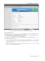
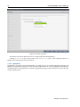
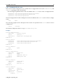
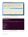
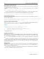
3.3.1 Welcome Screen
The welcome screen (figure 3.1) displays version and license information. Two installation modes are
available: normal mode and express mode. Selecting the express mode installs the head node with the
predefined configuration that the DVD was created with. The administrator password automatically set
when express mode is selected is: system.
Clicking on the Continue button brings up the Bright Cluster Manager software license screen,
described next.
© Bright Computing, Inc.
14
Installing Bright Cluster Manager
Figure 3.1: Installation welcome screen for Bright Cluster Manager
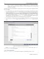
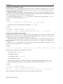
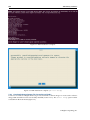
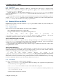
3.3.2 Software License
The “Bright Computing Software License” screen (figure 3.2) explains the applicable terms and
conditions that apply to use of the Bright Cluster Manager software.
Accepting the terms and conditions, and clicking on the Continue button leads to the Base
Distribution EULA (End User License Agreement) (figure 3.3).
Accepting the terms and conditions of the base distribution EULA, and clicking on the Continue
button leads to two possibilities.
1. If express mode was selected earlier, then the installer skips ahead to the Summary screen (figure 3.31), where it shows an overview of the predefined installation parameters, and awaits user
input to start the install.
2. Otherwise, if normal installation mode was selected earlier, then the “Kernel Modules” configuration screen is displayed, described next.
© Bright Computing, Inc.
3.3 Head Node Installation: Bare Metal Method
Figure 3.2: Bright Cluster Manager Software License
© Bright Computing, Inc.
15
16
Installing Bright Cluster Manager
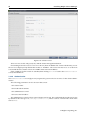
Figure 3.3: Base Distribution End User License Agreement
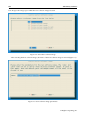
3.3.3 Kernel Modules Configuration
The Kernel Modules screen (figure 3.4) shows the kernel modules recommended for loading based
on hardware auto-detection.
© Bright Computing, Inc.
3.3 Head Node Installation: Bare Metal Method
17
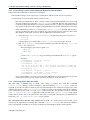
Figure 3.4: Kernel Modules Recommended For Loading After Probing
Changes to the modules to be loaded can be entered by reordering the loading order of modules, by
removing modules, and adding new modules. Clicking the + button opens an input box for adding a
module name and optional module parameters (figure 3.5).
© Bright Computing, Inc.
18
Installing Bright Cluster Manager
Figure 3.5: Adding Kernel Modules
Similarly, the - button removes a selected module from the list. The arrow buttons move a kernel
module up or down in the list. Kernel module loading order decides the exact name assigned to a device
(e.g. sda, sdb, eth0, eth1).
After optionally adding or removing kernel modules, clicking the reload button shows the modules
list that will then be implemented.
Clicking Continue then leads to the “Hardware Information” overview screen, described next.
3.3.4 Hardware Overview
The “Hardware Information” screen (figure 3.6) provides an overview of detected hardware depending on the kernel modules that have been loaded. If any hardware is not detected at this stage, the
“Go Back” button is used to go back to the “Kernel Modules” screen (figure 3.4) to add the appropriate modules, and then the “Hardware Information” screen is returned to, to see if the hardware
has been detected. Clicking Continue in this screen leads to the Nodes configuration screen, described
next.
© Bright Computing, Inc.
3.3 Head Node Installation: Bare Metal Method
19
Figure 3.6: Hardware Overview Based On Loaded Kernel Modules
3.3.5 Nodes Configuration
The Nodes screen (figure 3.7) configures the number of racks, the number of regular nodes, the node
basename, the number of digits for nodes, and the hardware manufacturer.
The maximum number of digits is 5, to keep the hostname reasonably readable.
The “Node Hardware Manufacturer” selection option initializes any monitoring parameters relevant for that manufacturer’s hardware. If the manufacturer is not known, then Other is selected from
the list.
Clicking Continue in this screen leads to the “Network Topology” selection screen, described
next.
© Bright Computing, Inc.
20
Installing Bright Cluster Manager
Figure 3.7: Nodes Configuration
3.3.6 Network Topology
Regular nodes are always located on an internal network, by default called Internalnet.
The “Network Topology” screen allows selection of one of three different network topologies.
A type 1 network (figure 3.8), with nodes connected on a private internal network. This is the default
network setup. In this topology, a network packet from a head or regular node destined for any
external network that the cluster is attached to, by default called Externalnet, can only reach
the external network by being routed and forwarded at the head node itself. The packet routing
for Externalnet is configured at the head node.
A type 2 network (figure 3.9) has its nodes connected via a router to a public network. In this topology, a
network packet from a regular node destined for outside the cluster does not go via the head node,
but uses the router to reach a public network. Packets destined for the head node however still go
directly to the head node. Any routing for beyond the router is configured on the router, and not on
the cluster or its parts. Care should be taken to avoid DHCP conflicts between the DHCP server on
the head node and any existing DHCP server on the internal network if the cluster is being placed
within an existing corporate network that is also part of Internalnet (there is no Externalnet
in this topology). Typically, in the case where the cluster becomes part of an existing network,
there is another router configured and placed between the regular corporate machines and the
cluster nodes to shield them from effects on each other.
A type 3 network (figure 3.10), with nodes connected on a routed public network. In this topology,
a network packet from a regular node, destined for another network, uses a router to get to it.
The head node, being on another network, can only be reached via a router too. The network
© Bright Computing, Inc.
3.3 Head Node Installation: Bare Metal Method
21
the regular nodes are on is called Internalnet by default, and the network the head node is on
is called Managementnet by default. Any routing configuration for beyond the routers that are
attached to the Internalnet and Managementnet networks is configured on the routers, and
not on the clusters or its parts.
Selecting the network topology helps decide the predefined networks on the Networks settings screen later (figure 3.15). Clicking Continue here leads to the “Additional Network
Configuration” screen, described next.
Figure 3.8: Networks Topology: nodes connected on a private internal network
© Bright Computing, Inc.
22
Installing Bright Cluster Manager
Figure 3.9: Networks Topology: nodes connected via router to a public network
© Bright Computing, Inc.
3.3 Head Node Installation: Bare Metal Method
23
Figure 3.10: Network Topology: nodes connected on a routed public network
3.3.7 Additional Network Configuration
The “Additional Network Configuration” screen (figure 3.11) allows the configuration of the
following extra networks:
1. additional high speed interconnect networks
2. BMC networks
© Bright Computing, Inc.
24
Installing Bright Cluster Manager
Figure 3.11: Additional Network Configuration: OFED and BMC Networking
• Additional High Speed Networks: The Additional high speed interconnect selector
options configure the compute nodes so that they communicate quickly with each other while
running computational workload jobs.
The choices include 10/40 Gig-E and InfiniBand RDMA OFED (figure 3.12). The regular nodes of
a cluster can be set to boot over the chosen option in both cases.
Figure 3.12: Additional Network Configuration: Interconnect Interface
In the case of InfiniBand, there are OFED stack driver options (figure 3.13).
© Bright Computing, Inc.
3.3 Head Node Installation: Bare Metal Method
25
Figure 3.13: Additional Network Configuration: OFED stack
The OFED stack used can be the stack packaged by the parent distribution, or it can be the appropriate (Mellanox or QLogic/Intel True Scale) InfiniBand hardware stack that is packaged by the
vendor. Currently, choosing the parent distribution stack is recommended because it tends to be
integrated better with the OS. OFED installation is discussed further in section 7.6.
• BMC Network Configuration: If the administrator confirms that the nodes are to use BMCs (Baseboard Management Controllers) that are compatible with IPMI, iLO, or CIMC, then the BMC network options appear (figure 3.14).
Figure 3.14: Additional Network Configuration: BMC Network
© Bright Computing, Inc.
26
Installing Bright Cluster Manager
These options configure the BMC network for the regular nodes:
– IPMI, iLO, or CIMC: sets the BMC network type.
– External Network, Internal Network, or Other: sets whether the ethernet segment
that the BMCs connect with is the internal network, the external network, or another network.
Depending on the assigned ethernet segment, further settings can be specified as indicated
by the following table:
Ethernet Segment
Setting
Internal
External
Other
Create new
layer-3 BMC
subnet?
Yes/No
Not applicable
Yes/No
Yes/No
Yes/No
Yes/No
Dedicate head
node interface for
BMC?
Yes/No
Yes/No
Yes/No
Automatically
Configure BMC
On Node Boot?
Not applicable
Yes/No
Yes/No
Use DHCP for
BMC?
If a BMC is to be used, then the BMC password is set to a random value. Retrieving and changing
a BMC password is covered in section 3.7.2 of the Administrator Manual. BMC configuration is
discussed further in section 3.7 of the Administrator Manual.
The remaining options—adding the network, and automatically configuring the network—can then
be set.
Clicking the Continue button shown in figure 3.11 or figure 3.14 leads to the Networks configuration screen, described next.
3.3.8 Networks Configuration
The Networks configuration screen (figure 3.15) displays the predefined list of networks, based on the
selected network topology. BMC and high speed interconnect networks are defined based on selections
made in the “Additional Network Configuration” screen earlier (figure 3.11).
© Bright Computing, Inc.
3.3 Head Node Installation: Bare Metal Method
27
Figure 3.15: Networks Configuration
The parameters of the network interfaces can be configured in this screen.
For a type 1 setup, an external network and an internal network are always defined.
For a type 2 setup only an internal network is defined and no external network is defined.
For a type 3 setup, an internal network and a management network are defined.
A pop-up screen is used to help fill these values in for a type 1 network. The values can be provided
via DHCP, but usually static values are used in production systems to avoid confusion. The pop-up
screen asks for IP address details for the external network, where the network externalnet corresponds to the site network that the cluster resides in (e.g. a corporate or campus network). The IP
address details are therefore the details of the head node for a type 1 externalnet network (figure 3.8).
Clicking Continue in this screen validates all network settings. Invalid settings for any of the defined networks cause an alert to be displayed, explaining the error. A correction is then needed to
proceed further.
If all settings are valid, the installation proceeds on to the Nameservers screen, described in the
next section.
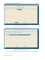
3.3.9 Nameservers And Search Domains
Search domains and external name servers can be added or removed using the Nameservers screen
(figure 3.16). Using an external name server is recommended. Clicking on Continue leads to the
“Network Interfaces” configuration screen, described next.
© Bright Computing, Inc.
28
Installing Bright Cluster Manager
Figure 3.16: Nameservers and search domains
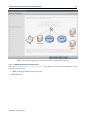
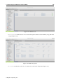
3.3.10 Network Interfaces Configuration
The “Network Interfaces” screen (figure 3.17) allows a review of the list of network interfaces with
their proposed settings. The head node and regular nodes each have a settings pane for their network
configurations. If a BMC network is to be shared with a regular network—which an option in the screen
shown in figure 3.14—then an alias interface is shown too. In figure 3.17 an alias interface, eth0:ipmi,
is shown.
© Bright Computing, Inc.
3.3 Head Node Installation: Bare Metal Method
29
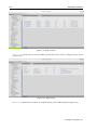
Figure 3.17: Network Interface Configuration
An icon in the Head Node Interfaces section, where the hovertext is showing in the figure, allows the Ethernet network interface order to be changed on the head node. For example, if the interfaces
with the names eth0 and eth1 need to be swapped around, clicking on the icon brings up a screen allowing the names to be associated with specific MAC addresses (figure 3.18).
© Bright Computing, Inc.
30
Installing Bright Cluster Manager
Figure 3.18: Network Interface Configuration Order Changing
For the node network interfaces of figure 3.17, the IP offset can be modified. 1
A different network can be selected for each interface using the drop-down box in the Network
column. Selecting Unassigned disables a network interface.
If the corresponding network settings are changed (e.g., base address of the network) the IP address
of the head node interface needs to be modified accordingly. If IP address settings are invalid, an alert
is displayed, explaining the error.
1 The IP offset is used to calculate the IP address assigned to a regular node interface. The nodes are conveniently numbered
in a sequence, so their interfaces are typically also given a network IP address that is in a sequence on a selected network. In
Bright Cluster Manager, interfaces by default have their IP addresses assigned to them sequentially, in steps of 1, starting after the
network base address.
The default IP offset is 0.0.0.0, which means that the node interfaces by default start their range at the usual default values in
their network.
With a modified IP offset, the point at which addressing starts is altered. For example, a different offset might be desirable
when no IPMI network has been defined, but the nodes of the cluster do have IPMI interfaces in addition to the regular network
interfaces. If a modified IP offset is not set for one of the interfaces, then the BOOTIF and ipmi0 interfaces get IP addresses
assigned on the same network by default, which could be confusing.
However, if an offset is entered for the ipmi0 interface, then the assigned IPMI IP addresses start from the IP address specified
by the offset. That is, each modified IPMI address takes the value:
address that would be assigned by default + IP offset
Example
Taking the case where BOOTIF and IPMI interfaces would have IP addresses on the same network with the default IP offset:
Then, on a cluster of 10 nodes, a modified IPMI IP offset of 0.0.0.20 means:
• the BOOTIF interfaces stay on 10.141.0.1,...,10.141.0.10 while
• the IPMI interfaces range from 10.141.0.21,...,10.141.0.30
© Bright Computing, Inc.
3.3 Head Node Installation: Bare Metal Method
31
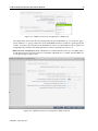
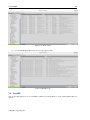
Clicking Continue on a “Network Interfaces” screen validates IP address settings for all node
interfaces.
If all settings are correct, and if InfiniBand networks have been defined, then clicking on Continue
leads to the “Subnet Managers” screen (figure 3.19), described in the next section.
If no InfiniBand networks are defined, or if InfiniBand networks have not been enabled on the networks settings screen, then clicking Continue instead leads to the CD/DVD ROMs selection screen (figure 3.20).
3.3.11 Select Subnet Managers
The “Subnet Managers” screen in figure 3.19 is only displayed if an InfiniBand network was defined,
and lists all the nodes that can run the InfiniBand subnet manager. The nodes assigned the role of
a subnet manager are ticked, and the Continue button is clicked to go on to the “CD/DVD ROMs”
selection screen, described next.
Figure 3.19: Subnet Manager Nodes
3.3.12 Select CD/DVD ROM
The “CD/DVD ROMs” screen in figure 3.20 lists all detected CD/DVD-ROM devices. If multiple drives
are found, then the drive with the Bright Cluster Manager DVD needs to be selected by the administrator. If the installation source is not detected, it can be added manually using the + button.
Optionally, a media integrity check can be set.
Clicking on the Continue button starts the media integrity check, if it was set. The media integrity
check can take about a minute to run. If all is well, then the “Workload Management” setup screen is
displayed, as described next.
© Bright Computing, Inc.
32
Installing Bright Cluster Manager
Figure 3.20: DVD Selection
3.3.13 Workload Management Configuration
The “Workload Management” configuration screen (figure 3.21) allows selection from a list of supported workload managers. A workload management system is highly recommended to run multiple
compute jobs on a cluster.
© Bright Computing, Inc.
3.3 Head Node Installation: Bare Metal Method
33
Figure 3.21: Workload Management Setup
The Maui and Moab scheduler can be configured to run on the cluster if selected. However, these are
not installed by the Bright Cluster Manager installer because Adaptive Computing prefers to distribute
them directly. Details on installing the packages after the cluster has been installed are given in Chapter 7
on workload management of the Administrator Manual.
To prevent a workload management system from being set up, the option to select is: None. If a
workload management system is selected, then the number of slots per node is set by default to 8.
The head node can also be selected for use as a compute node, which can be a sensible choice on
small clusters.
Clicking Continue on this screen leads to the “Hadoop” screen for the Bright Cluster Manager
Hadoop edition, described next.
3.3.14 Hadoop
The Bright Cluster Manager Hadoop edition can be configured to support Hadoop installation in this
screen (figure 3.22).
Hadoop is used for processing extremely large unstructured data. It is available in several flavors,
and evolving rapidly. It can therefore be hard to manage. The introduction of Hadoop integration for
the main Hadoop flavors in version Bright Cluster Manager 7.1 makes its installation, configuration,
and support much simpler for cluster administrators.
Bright Cluster Manager provides the Apache, Cloudera, and Hortonworks flavors of Hadoop.
© Bright Computing, Inc.
34
Installing Bright Cluster Manager
Figure 3.22: Hadoop Option
The Hadoop Deployment Manual has more on deploying and running Hadoop.
Clicking Continue on this screen leads to the “OpenStack” screen, if the OpenStack edition of
Bright Cluster Manager has been purchased.
3.3.15 OpenStack
OpenStack is an Open Source implementation of cloud services. It is under rapid development, but
Bright Cluster Manager integrates a relatively stable implementation of it in the Bright Cluster Manager
OpenStack edition. Selecting it means that the OpenStack packages will be installed onto the head node,
ready for deployment.
© Bright Computing, Inc.
3.3 Head Node Installation: Bare Metal Method
Figure 3.23: OpenStack Option
Clicking Continue on this screen leads to the “Ceph” screen.
© Bright Computing, Inc.
35
36
3.3.16
Installing Bright Cluster Manager
Ceph
Figure 3.24: Ceph Option
Ceph is an object-based distributed parallel filesystem with self-managing and self-healing features.
Object-based means it handles each item natively as an object, along with meta-data for that item. Ceph
is typically used with OpenStack, but it can also be used for storage independently from OpenStack.
Selecting Ceph in this screen means that the Ceph packages will be installed onto the head node, ready
for deployment.
Clicking Continue on this screen leads to the “Disk Partitioning and Layouts” screen, described next.
3.3.17 Disk Partitioning And Layouts
The partitioning layout XML schema is described in detail in Appendix D of the Administrator Manual.
Within the “Disk Partitioning and Layouts” configuration screen (figure 3.25):
© Bright Computing, Inc.
3.3 Head Node Installation: Bare Metal Method
37
Figure 3.25: Disk Partitioning And Layouts
• the administrator must select the drive on the head node where the cluster manager is to be installed.
• the administrator must set the disk partitioning layout for the head node and regular nodes with
the two options: “Head node disk layout” and “Node disk layout”.
–
* The head node by default uses
· one big partition if it has a drive size smaller than about 500GB
· several partitions if it has a drive size greater than or equal to about 500GB.
The
regular node by default uses several partitions.
*
A partitioning layout other than the default can be selected for installation from the dropdown boxes for the head node and regular nodes. Possible partitioning options include RAID,
failover, and STIG-compliant schemes.
A custom partitioning layout can also be used by adding the file to the options with the +
button.
– The head node partitioning layout is the only installation setting that cannot easily be changed
after the completion (section 3.3.23) of installation. It should therefore be decided upon with
care.
– By default, Bright Cluster Manager mounts ext2/3/4 filesystems on the head node with ACLs
set and extended attributes set.
– A text editor pops up when the edit button of a partitioning layout is clicked (figure 3.26). This
allows the administrator to view and change layout values within the layout’s configuration
XML file using the schema in Appendix D.1 of the Administrator Manual.
© Bright Computing, Inc.
38
Installing Bright Cluster Manager
The Save and Reset buttons are enabled on editing, and save or undo the text editor
changes. Once saved, the changes cannot be reverted automatically in the text editor, but
must be done manually.
The XML schema allows the definition of a great variety of layouts in the layout’s configuration XML
file. For example:
1. for a large cluster or for a cluster that is generating a lot of monitoring or burn data, the default
partition layout partition size for /var may fill up with log messages because log messages are
usually stored under /var/log/. If /var is in a partition of its own, as in the default head node
partitioning layout presented when the hard drive is about 500GB or more, then providing a larger
size of partition than the default for /var allows more logging to take place before /var is full.
Modifying the value found within the <size></size> tags associated with that partition in the
XML file (figure 3.26) modifies the size of the partition that is to be installed.
2. the administrator could specify the layout for multiple non-RAID drives on the head node using
one <blockdev></blockdev> tag pair within an enclosing <device></device> tag pair for each
drive.
Figure 3.26: Edit Head Node Disk Partitioning
Clicking Continue on the “Disk Partitioning and Layouts” screen leads to the “Time
Configuration” screen, described next.
3.3.18 Time Configuration
The “Time Configuration” screen (figure 3.27) displays a predefined list of time servers.
© Bright Computing, Inc.
3.3 Head Node Installation: Bare Metal Method
39
Figure 3.27: Time Configuration
Timeservers can be removed by selecting a time server from the list and clicking the - button.
Additional time servers can be added by entering the name of the time server and clicking the + button.
A timezone can be selected from the drop-down box if the default is incorrect. Clicking Continue leads
to the “Cluster Access” screen, described next.
3.3.19 Cluster Access
The “Cluster Access” screen (figure 3.28) sets the existence of a cluster management web portal
service, and also sets network access to several services.
© Bright Computing, Inc.
40
Installing Bright Cluster Manager
Figure 3.28: Cluster Access
These services are the web portal, ssh, and the cluster management daemon.
If restricting network access for a service is chosen, then an editable list of networks that may access
the service is displayed. By default the list has no members. The screen will not move on to the next
screen until the list contains at least one CIDR-format network IP address.
If the conditions for this screen are satisfied, then clicking Continue leads to the Authentication
screen, described next.
3.3.20 Authentication
The Authentication screen (figure 3.29) requires the password to be set twice for the cluster administrator.
The following parameters can also be set in this screen:
• the cluster name
• the head node hostname
• the administrator e-mail
• the test e-mail checkbox
The administrator e-mail is where critical cluster mail is sent. If it is left blank then such mail is sent
by default to the mail spool at /var/spool/mail/root, where it can be viewed with a mail client
such as mutt.
© Bright Computing, Inc.
3.3 Head Node Installation: Bare Metal Method
41
If the Send test email on first boot checkbox is checked, then a test mail is sent the first
time that the head node boots after installation, so that the administrator can verify that the mail system
is working as expected.
Clicking Continue validates the passwords that have been entered, and if successful, leads to the
Console screen, described next.
Figure 3.29: Authentication
3.3.21 Console
The Console screen (figure 3.30) allows selection of a graphical mode or a text console mode for when
the head node or regular nodes boot. Clicking Continue leads to the Summary screen, described next.
© Bright Computing, Inc.
42
Installing Bright Cluster Manager
Figure 3.30: Console
3.3.22 Summary
The Summary screen (figure 3.31), summarizes some of the installation settings and parameters configured during the previous stages. If the express mode installation was chosen, then it summarizes the
predefined settings and parameters. Changes to the values on this screen are made by navigating to
previous screens and correcting the values there.
When the summary screen displays the right values, clicking on the Start button leads to the
“Installation Progress” screen, described next.
© Bright Computing, Inc.
3.3 Head Node Installation: Bare Metal Method
43
Figure 3.31: Summary of Installation Settings
3.3.23 Installation
The “Installation Progress” screen (figure 3.32) shows the progress of the installation. It is not
possible to navigate back to previous screens once the installation has begun. When the installation is
complete (figure 3.33), the installation log can be viewed in detail by clicking on “Install Log”.
The Reboot button restarts the machine. The BIOS boot order may need changing or the DVD
should be removed, in order to boot from the hard drive on which Bright Cluster Manager has been
installed.
© Bright Computing, Inc.
44
Installing Bright Cluster Manager
Figure 3.32: Installation Progress
© Bright Computing, Inc.
3.4 Head Node Installation: Add-On Method
45
Figure 3.33: Installation Completed
After rebooting, the system starts and presents a login prompt. After logging in as root using the
password that was set during the installation procedure, the system is ready to be configured. If express
installation mode was chosen earlier as the install method, then the password is preset to system.
3.3.24 Licensing And Further Configuration
The administrator with no interest in the add-on method of installation can skip on to installing the
license (Chapter 4). After that, the administrator can look through the Administrator Manual, where tools
and concepts used with Bright Cluster Manager and introduced, so that further cluster configuration can
be carried out.
3.4
Head Node Installation: Add-On Method
An add-on installation, in contrast to the bare metal installation (section 3.3), is an installation that is done
onto a machine that is already running one of the supported distributions of section 2.1. The installation
of the distribution can therefore be skipped for this case. However, unlike the bare metal installation, the
add-on is not recommended for inexperienced cluster administrators. This is because of the following
reasons:
• The installation configuration may conflict with what has already been installed. The problems
that arise can always be resolved, but an administrator that is not familiar with Bright Cluster
Manager should be prepared for troubleshooting.
• After the add-on installation has been done to the head node, a software image for the regular
nodes must still be installed into a directory on the head node. The software image is what is
© Bright Computing, Inc.
46
Installing Bright Cluster Manager
provisioned to regular nodes when they are powered up. The creation and installation of a software image requires some understanding of the Linux operating system as well as Bright Cluster
Manager. Software image management is described in section 8.6 of the Administrator Manual.
3.4.1 Prerequisites
For the add-on method
• The operating system must obviously follow system administration best practices so that it works
properly with the official distribution, when Bright Cluster Manager is added on
• The items of software that Bright Cluster Manager adds must be allowed to overrule in any conflict
with what is already installed, or the end result of the installation cannot be supported.
• It is highly recommended to use a freshly-installed distribution rather than one which is already
in use.
• A product key is needed
• There must be repository access to the supported distribution.
– Internet access makes up-to-date repository access possible. RHEL and SLES repository access requires a subscription from Red Hat or SUSE (Chapter 5).
– For high-security environments without internet access, an alternative is to mount a DVD
device or ISO image to the head node containing a local repository snapshot of the parent
distribution, and specify the repository location when running the installation command.
Configuring a local repository is described in section 8.6.3 of the Administrator Manual.
3.4.2 Installing The Installer
To carry out an add-on installation, the bright-installer-7.1 package must be installed with a
package installer.
The bright-installer-7.1 package can be obtained from a Bright Cluster Manager installation DVD, in the directory /addon/.
The file name is something like
bright-installer-7.1-129_cmbright.noarch.rpm (the exact version number may differ).
After obtaining the package, it is installed as root on the node that is to become the head node, as
follows:
[root@rhel6 ~]# rpm -ivh bright-installer-bright-129_cmbright.\
noarch.rpm
Because the installation of the package is done using rpm directly, and is not using a dependency
resolver such as YUM, some packages may still need to be installed first. The administrator is prompted
by the installer to install these packages, and they can be installed with YUM as usual. Installation
progress is logged in /var/log/install-bright.log.
3.4.3
Running The Installer
The Help Text For install-bright
The installer is run with the command install-bright. Running it without options displays the
following help text:
[root@rhel6 ~]# install-bright
USAGE: install-bright <-d <path>|-n|-l> [EXTRA OPTIONS]
-d | --fromdvd
<path to dvd>
Path to a Bright DVD/USB device,
or mounted directory or path to a
© Bright Computing, Inc.
3.4 Head Node Installation: Add-On Method
-n | --network
-l | --localrepo
47
Bright ISO file
Install over network
Do not update any repo configuration,
just use existing repository settings
EXTRA OPTIONS:
--------------h | --help
-c | --useconfig
-v | --verbose
-m | --minimal
Print this help
<path to config> Use predefined config file
Turn on verbose mode
Only install Bright packages and
dependencies
-f | --ignoreconflicts
Ignore package conflicts check
-s | --skippackagesetup
Skip repository configuration,
validation and package installation
-x | --excludepackages
Exclude packages from the list of
packages to be installed (commaseparated)
EXAMPLES:
--------1. install-bright -n
2. install-bright -l
3. install-bright -d /dev/sr0
4. install-bright -d /media/Bright-DVD
5. install-bright -d /tmp/bright7.0-rhel6u5.iso
6. install-bright -d /tmp/bright7.0-rhel6u5.iso -x
libXTrap,xorg-x11-resutils
Usage Examples For install-bright
• Install Bright Cluster Manager directly from the Bright Computing repositories over the internet:
install-bright -n
• Install Bright Cluster Manager using a Bright Computing DVD as the package repository:
install-bright -d /dev/sr0
• Install Bright Cluster Manager using a Bright Computing ISO as the package repository:
install-bright -d /tmp/bright-centos5.iso
• Install Bright Cluster Manager using a Bright Computing ISO (-d option) as the package repository, and create the repository (-r option) in the specified directory:
install-bright -d /tmp/bright-centos5.iso -r /tmp/repodir
• Install Bright Cluster Manager using a Bright Computing ISO as the package repository (-d option), and create the repository in the specified directory (-r option), but overwrite contents (-o
option), if the directory already exists:
install-bright -d /tmp/bright-centos5.iso -r /tmp/repodir -o
• Install Bright Cluster Manager from a local repository which has already been configured. This
also assumes that the repository configuration files for zypper/YUM use are already in place:
© Bright Computing, Inc.
48
Installing Bright Cluster Manager
install-bright -l
• Install Bright Cluster Manager from a local repository (-l option) which has already been configured, and specify a path to the repository directory with the -r option. This can be used when the
repository configuration file has not yet been generated and created. A repository configuration
file is generated, and placed permanently in the appropriate directories (/etc/yum.repos.d/
or /etc/zypp/repos.d/):
install-bright -l -r /tmp/repodir
An Installation Run For install-bright
The most common installation option is with an internet connection. Any required software packages
are asked for at the start:
Example
[root@rhel6 ~]# install-bright -n
Please install the follow pre-requisites
---------------------------------------createrepo
[root@rhel6 ~]# yum install createrepo
...
After all the packages are installed on the head node, the installer can be run again. It checks for some
software conflicts, and warns about the ones it runs into.:
Example
[root@rhel6 ~]# install-bright -n
INFO/ERROR/WARNING:
-------------------WARNING:
A DHCP daemon is already running. Bright Cluster Manager
provides a customized DHCP server, and will update the
’dhcpd’ configuration files. It is highly recommended
that you stop your existing DHCP server, and let Bright
Cluster Manager configure your dhcp server.
You can also choose to ignore this message, and proceed
with the existing DHCP server, which may or may not work.
-------------------Continue(c)/Exit(e)? e
[root@rhel6 ~]# service dhcpd stop
Shutting down dhcpd:
[
OK
]
Having resolved potential software conflicts, the product key (supplied by Bright Computing or its
vendor) is supplied:
Example
[root@rhel6 ~]# install-bright -n
Bright Cluster Manager Product Key Activation
--------------------------------------------Product key [XXXXX-XXXXX-XXXXX-XXXXX-XXXXX]: 001323-134122-134134-314384-987986
© Bright Computing, Inc.
3.4 Head Node Installation: Add-On Method
...
License Parameters
-----------------Country Name (2 letter code) []:
State or Province Name (full name) []:
Locality (city) []:
Organization Name (e.g. company) []:
Organization Unit (e.g. department) []:
Cluster Name []:
MAC address [??:??:??:??:??:??]:
49
US
CA
San Francisco
Bright
Development
bright71
08:B8:BD:7F:59:4B
Submit certificate request to Bright Computing? [y(yes)/n(no)]: y
Contacting license server ... License granted.
License has been installed in /cm/local/apps/cmd/etc/
The software license is displayed, and can be clicked through. Some warning is given about the
configuration changes about to take place:
Please be aware that the Bright Cluster Manager will re-write the
following configuration on your system:
- Update network configuration files.
- Start a DHCP server on the management network.
- Update syslog configuration
The software configuration sections is reached. Default Bright Cluster Manager values are provided,
but should normally be changed to appropriate values for the cluster. Questions asked are:
Management network parameters
----------------------------Network Name [internalnet]:
Base Address [10.141.0.0]:
Netmask Bits [16]:
Domain Name [eth.cluster]:
Management interface parameters
------------------------------Interface Name [eth0]:
IP Address [10.141.255.254]:
External network parameters
--------------------------Network Name [externalnet]:
Base Address [DHCP]:
Netmask Bits [24]:
Domain Name []: cm.cluster
External interface parameters
----------------------------Interface Name [eth1]:
IP Address [DHCP]:
External name servers list (space separated)
-------------------------------------------List [10.150.255.254]:
© Bright Computing, Inc.
50
Installing Bright Cluster Manager
Root password
------------Please enter the cluster root password:
MySQL root password
------------------Please enter the MySQL root password:
The Bright Cluster Manager packages are then installed and configured. The stages include, towards
the end:
Example
Setting up repositories
Installing required packages
Updating database authentication
Setting up MySQL database
Starting syslog
Initializing cluster management daemon
Generating admin certificates
Starting cluster management daemon
.....
.....
.....
.....
.....
.....
.....
.....
[
[
[
[
[
[
[
[
OK
OK
OK
OK
OK
OK
OK
OK
]
]
]
]
]
]
]
]
If all is well, a congratulatory message then shows up, informing the administrator that Bright Cluster Manager has been installed successfully, that the host is now a head node.
Installing The Software Image For Regular Nodes After The install-bright Installation Run
A functional cluster needs regular nodes to work with the head node. The regular nodes at this point
of the installation still need to be set up. To do that, a software image (section 2.1.2 of the Administrator
Manual) must now be created for the regular nodes on the head node. The regular nodes, when booting,
use such a software image when they boot up to become a part of the cluster. A software image can be
created using the base tar image included on the DVD, or as a custom image. The details on how to do
this with cm-create-image are given in section 8.6 of the Administrator Manual.
Once the head node and software image have been built, the head node installation is complete, and
the cluster is essentially at the same stage as that at the end of section 3.3.23 of the bare metal installation,
except for that the software image is possibly a more customized image than the default image provided
with the bare-metal installation.
The Build Configuration Files
This section is mainly intended for deploying installations that have been pre-configured by the administrator. It can therefore be skipped in a first reading.
The build configuration file of a cluster contains the configuration scheme for a cluster. The bare
metal and add-on installations both generate their own, separate build configuration files, stored in
separate locations.
Most administrators do not deal with a build configuration file directly, partly because a need to do
this arises only in rare and special cases, and partly because it is easy to make mistakes. An overview,
omitting details, is given here to indicate how the build configuration file relates to the installations
carried out in this chapter and how it may be used.
The bare metal build configuration file: The file at:
/root/cm/build-config.xml
on the head node contains cluster configuration settings and the list of distribution packages that are
installed during the bare metal installation. Once the installation has completed, this file is static, and
does not change as the cluster configuration changes.
© Bright Computing, Inc.
3.4 Head Node Installation: Add-On Method
51
The add-on installation build configuration file: Similarly, the file at:
/root/.brightcm/build-config.xml
contains configuration settings. However, it does not contain a list of distribution packages. The file
is created during the add-on installation, and if the installation is interrupted, the installation can be
resumed at the point of the last confirmation prior to the interruption. This is done by using the -c
option to install-bright as follows:
Example
install-bright -c /root/.brightcm/build-config.xml
Both original “build” configuration XML files can be copied and installed via the -i initialize option:
For example:
service cmd stop
cmd -i build-config-copy.xml
service cmd start
#reinitializes CMDaemon from scratch
overwrites the old configuration. It means that the new cluster presents the same cluster manager configuration as the old one did initially. This can only be expected to work with identical hardware because
of hardware dependency issues.
An XML configuration file can be exported via the -x option to cmd: For example:
service cmd stop
cmd -x myconfig.xml
service cmd start
Exporting the configuration is sometimes helpful in examining the XML configuration of an existing
cluster after configuration changes have been made to the original installation. This “snapshot” can
then, for example, be used to customize a build-config.xml file in order to deploy a custom version
of Bright Cluster Manager.
An exported configuration cannot replace the original bare-metal build-config.xml during the
installation procedure. For example, if the original bare-metal file is replaced by the exported version
by opening up another console with alt-f2, before the point where the “Start” button is clicked
(figure 3.31), then the installation will fail. This is because the replacement does not contain the list of
packages to be installed.
The exported configuration can however be used after a distribution is already installed. This is
true for a head node that has been installed from bare-metal, and is also true for a head node that has
undergone or is about to undergo an add-on installation. This is because a head node does not rely on a
packages list in the XML file in the case of
• after a bare-metal installation, and
• before or after an add-on installation.
These possibilities for an export file are indicated by the following table:
Can the cmd -x export file be used as-is for cluster installation?
install type
before or after installation
cluster installs from export?
bare metal
before
no
bare metal
after
yes
add-on install
before
yes
add-on install
after
yes
© Bright Computing, Inc.
4
Licensing Bright Cluster
Manager
This chapter explains how a Bright Cluster Manager license is viewed, verified, requested, and installed.
After installing a new cluster, it is typically installed with a temporary, or evaluation license, which
allows the administrator to try out Bright Cluster Manager. This typically has some restrictions on the
period of validity for the license, or the number of nodes in the cluster.
Installing a full license allows the cluster to function without the restrictions of the evaluation license.
The administrator therefore usually requests a full license, and installs it. This normally only requires
the administrator to:
• Have the product key at hand
• Run the request-license script on the head node
The preceding takes care of the licensing needs for most administrators, and the rest of this chapter
can then usually conveniently be skipped.
Administrators who would like a better background understanding on how licensing is installed
and used in Bright Cluster Manager can go on to read the rest of this chapter.
Only after a license is installed, can CMDaemon run. CMDaemon is the engine that runs Bright
Cluster Manager, and is what is normally recommended for further configuration of the cluster. Basic
CMDaemon-based cluster configuration is covered in Chapter 3 of the Administrator Manual.
Any Bright Cluster Manager installation requires a license file to be present on the head node. The
license file details the attributes under which a particular Bright Cluster Manager installation has been
licensed.
Example
• the “Licensee” details, which include the name of the organization, is an attribute of the license
file that specifies the condition that only the specified organization may use the software
• the “Licensed nodes” attribute specifies the maximum number of nodes that the cluster manager may manage. Head nodes are regarded as nodes too for this attribute.
• the “Expiration date” of the license is an attribute that sets when the license expires. It is
sometimes set to a date in the near future so that the cluster owner effectively has a trial period. A
new license with a longer period can be requested (section 4.3) after the owner decides to continue
using the cluster with Bright Cluster Manager
A license file can only be used on the machine for which it has been generated and cannot be changed
once it has been issued. This means that to change licensing conditions, a new license file must be issued.
© Bright Computing, Inc.
54
Licensing Bright Cluster Manager
The license file is sometimes referred to as the cluster certificate, or head node certificate, because it
is the X509v3 certificate of the head node, and is used throughout cluster operations. Its components
are located under /cm/local/apps/cmd/etc/. Section 2.3 of the Administrator Manual has more
information on certificate-based authentication.
4.1
Displaying License Attributes
Before starting the configuration of a cluster, it is important to verify that the attributes included in the
license file have been assigned the correct values. The license file is installed in the following location:
/cm/local/apps/cmd/etc/cert.pem
and the associated private key file is in:
/cm/local/apps/cmd/etc/cert.key
To verify that the attributes of the license have been assigned the correct values, the License tab of the
GUI can be used to display license details (figure 4.1):
Figure 4.1: License Information
Alternatively the licenseinfo in cmsh main mode may be used:
Example
[root@bright71 ~]# cmsh
[bright71]% main licenseinfo
License Information
----------------------- ------------------------------------------Licensee
/C=US/ST=California/L=San Jose/O=Bright
Computing/OU=Temporary Licensing/CN=003040
Serial Number
4411
Start Time
Tue Apr 24 00:00:00 2012
End Time
Mon Dec 31 23:59:59 2012
Version
7.1
Edition
Advanced
Pre-paid Nodes
10
Max Pay-per-use Nodes
1000
Node Count
2
MAC Address / Cloud ID 00:0C:29:E2:DA:2D
© Bright Computing, Inc.
4.2 Verifying A License—The verify-license Utility
55
The license in the example above allows 1000 pay-per-use nodes to be used. It is tied to a specific
MAC address, so it cannot simply be used elsewhere. For convenience, the Node Count field in the
output of licenseinfo shows the current number of nodes used.
4.2
Verifying A License—The verify-license Utility
4.2.1 The verify-license Utility Can Be Used When licenseinfo Cannot Be Used
Unlike the licenseinfo command in cmsh (section 4.1), the verify-license utility can check licenses even if the cluster management daemon is not running.
When an invalid license is used, the cluster management daemon cannot start. The license problem
is logged in the cluster management daemon log file:
Example
[root@bright71 ~]# service cmd start
Waiting for CMDaemon to start...
CMDaemon failed to start please see log file.
[root@bright71 ~]# tail -1 /var/log/cmdaemon
Dec 30 15:57:02 bright71 CMDaemon: Fatal: License has expired
but further information cannot be obtained using cmgui and cmsh, because these clients themselves
obtain their information from the cluster management daemon.
In such a case, the verify-license utility allows the troubleshooting of license issues.
4.2.2 Using The verify-license Utility To Troubleshoot License Issues
There are four ways in which the verify-license utility can be used:
1. Using verify-license with no options: simply displays a usage text:
Example
[root@bright71 ~]# verify-license
Usage: /cm/local/apps/cmd/sbin/verify-license <path to certificate> \
<path to keyfile> <verify|info|monthsleft[=12]>
2. Using verify-license with the info option: prints license details:
Example
[root@bright71 ~]# cd /cm/local/apps/cmd/etc/
[root@bright71 etc]# verify-license cert.pem cert.key info
========= Certificate Information ===========
Version:
7.1
Edition:
Advanced
Common name:
bright71
Organization:
Bright Computing
Organizational unit:
Development
Locality:
San Jose
State:
California
Country:
US
Serial:
4411
Starting date:
24 Apr 2012
Expiration date:
31 Dec 2012
MAC address:
00:0C:29:E2:DA:2D
Pre-paid nodes:
10
Max Pay-per-use Nodes:
1000
=============================================
[root@bright71 etc]#
© Bright Computing, Inc.
56
Licensing Bright Cluster Manager
3. Using verify-license with the verify option: checks the validity of the license:
• If the license is valid, then no output is produced and the utility exits with exit-code 0.
• If the license is invalid, then output is produced indicating what is wrong. Messages such as these
are then displayed:
– If the license is old:
Example
[root@bright71 etc]# verify-license cert.pem cert.key verify
License has expired
License verification failed.
– If the certificate is not from Bright Computing:
Example
[root@bright71 etc]# verify-license cert.pem cert.key verify
Invalid license: This certificate was not signed by
Bright Computing
License verification failed.
4. Using verify-license with the monthsleft[=<value>] option: If a number is set for monthsleft
which is less than the number of months left until the license expires, then the verify-license command returns nothing. Otherwise the date of expiry for the license is displayed.
Example
[root@bright71 etc]# date
Tue Mar 12 14:23:21 CET 2013
[root@bright71 etc]# verify-license cert.{pem,key}
Bright Cluster Manager License expiration date: 31
[root@bright71 etc]# verify-license cert.{pem,key}
[root@bright71 etc]# verify-license cert.{pem,key}
Bright Cluster Manager License expiration date: 31
4.3
monthsleft
Dec 2013
monthsleft=9
monthsleft=10
Dec 2013
Requesting And Installing A License Using A Product Key
The license file is introduced at the start of this chapter (Chapter 4). As stated there, most administrators
that have installed a new cluster, and who need to install a license on the cluster in order to make their
Bright Cluster Manager fully functional, only need to do the following:
• Have their product key at hand
• Run the install-license script on the head node
The details of this section are therefore usually only of interest if a more explicit understanding of
the process is required for some reason.
4.3.1 Is A License Needed?—Verifying License Attributes
Before installing a license, the license attributes should be verified (section 4.2) to check if installation is
actually needed. If the attributes of the license are correct, the remaining parts of this section (4.3) may
safely be skipped. Otherwise the product key (page 57) is used to install a license.
Incorrect license attributes will cause cluster configuration to fail or may lead to a misconfigured
cluster. A misconfigured cluster may, for example, not have the ability to handle the full number of
nodes. In particular, the license date should be checked to make sure that the license has not expired. If
© Bright Computing, Inc.
4.3 Requesting And Installing A License Using A Product Key
57
the license is invalid, and it should be valid according to the administrator, then the Bright Computing
reseller that provided the software should be contacted with details to correct matters.
If Bright Cluster Manager is already running with a regular license, and if the license is due to expire,
then reminders are sent to the administrator e-mail address (page 54 of the Administrator Manual).
4.3.2 The Product Key
The product key looks like: the following pattern of digits:
000354-515786-112224-207441-186713
The product key allows: the administrator:
• to obtain and activate a license, which allows the cluster to function
• to register the key using the Bright Computing customer portal account. This allows cluster extension cloudbursting (Chapter 3 of the Cloudbursting Manual) to function.
The following terminology is used: when talking about product keys, locking, licenses, installation,
and registration:
• activating a license: A product key is obtained from any Bright Cluster Manager reseller. It is
used to obtain and activate a license file. Activation means that Bright Computing records that the
product key has been used to obtain a license file. The license obtained by product key activation
permits the cluster to work with particular settings. For example, the period of use and the number
of nodes.
• locking a product key: The administrator is normally allowed to use a product key to activate a
license only once. This is because a product key is locked on activation of the license. A locked state
means that product key cannot activate a new license—it is “used up”.
An activated license only works on the hardware that the product key was used with.This could
obviously be a problem if the administrator wants to move Bright Cluster Manager to new hardware. In such a case, the locked state is revocable by sending a request to Bright Computing to
unlock the product key. A product key that is unlocked can be used once again to activate a new
license.
• license installation: License installation occurs on the cluster after the license is activated and issued. The installation is done automatically if possible. Sometimes installation needs to be done
manually, as explained in the section on the request-license script (page 57). The license can
only work on the hardware it was specified for. After installation is complete, the cluster runs with
the activated license.
• product key registration: Product key registration occurs on the customer portal account when the
product key is associated with the account. Registered customers can view their cloud services
billing information amongst other items.
4.3.3 Requesting A License With The request-license Script
If the license has expired, or if the license attributes are otherwise not correct, a new license file must be
requested.
The request for a new license file is made using a product key (page 57) with the request-license
command.
The request-license command is used to request and activate a license, and works most conveniently with a cluster that is able to access the internet. The request can also be made regardless of
cluster connectivity to outside networks.
There are four options to use the product key to get the license:
© Bright Computing, Inc.
58
Licensing Bright Cluster Manager
1. Direct WWW access: If the cluster has access to the WWW port, then a successful completion of
the request-license command obtains and activates the license. It also locks the product key.
• Proxy WWW access: If the cluster uses a web-proxy, then the environment variable
http_proxy must be set before the request-license command is run. From a bash
prompt this is set with:
export http_proxy=<proxy>
where <proxy> is the hostname or IP address of the proxy. An equivalent alternative is
that the ScriptEnvironment directive (page 525 of the Administrator Manual), which is a
CMDaemon directive, can be set and activated (page 509 of the Administrator Manual).
2. Off-cluster WWW access: If the cluster does not have access to the WWW port, but
the administrator does have off-cluster web-browser access, then the point at which
the
request-license
command
prompts
“Submit certificate request to
http://support.brightcomputing.com/licensing/ ?”
should be answered negatively. CSR (Certificate Sign Request) data generated is then conveniently displayed on the screen
as well as saved in the file /cm/local/apps/cmd/etc/cert.csr.new. The cert.csr.new
file may be taken off-cluster and processed with an off-cluster browser.
The CSR file should not be confused with the private key file, cert.key.new, created shortly
beforehand by the request-license command. In order to maintain cluster security, the private
key file must, in principle, never leave the cluster.
At the off-cluster web-browser, the administrator may enter the cert.csr.new content in a web
form at:
http://support.brightcomputing.com/licensing
A signed license text is returned. At Bright Computing the license is noted as having been activated, and the product key is locked.
The signed license text received by the administrator is in the form of a plain text certificate. As
the web form response explains, it can be saved directly from most browsers. Cutting and pasting
the text into an editor and then saving it is possible too, since the response is plain text. The signed
license file, <signedlicense>, should then be put on the head node. If there is a copy of the file
on the off-cluster machine, the administrator should consider wiping that copy in order to reduce
information leakage.
The command:
install-license <signedlicense>
installs the signed license on the head node, and is described further on page 59. Installation
means the cluster now runs with the activated certificate.
3. E-mail access: If web access of any kind is denied to the administrator on- or off-cluster, but e-mail
is allowed, then the procedure of option 2 can be followed partially.
That is, instead of processing the cert.csr.new file with an off-cluster browser, the file is sent
using an e-mail client to [email protected]. The client can be on-cluster, if permitted,
or it can be off-cluster.
As in option 2, the CSR file should not be confused with the private key file, cert.key.new,
which must, in principle, never leave the cluster.
A signed certificate will be e-mailed back from the Bright Cluster Manager License Desk. The license will be noted by Bright Computing as having been activated, and the product key is put in
a locked state. The signed certificate file, <signedlicense>, can then be handled further as described in option 2. That is, it is saved to the head node and installed with the install-license
command.
© Bright Computing, Inc.
4.3 Requesting And Installing A License Using A Product Key
59
4. Fax or physical delivery: If no internet access is available at all to the administrator, the CSR data
may be faxed or sent as a physical delivery (postal mail print out, USB flash drive/floppy disk) to
any Bright Cluster Manager reseller. A certificate will be faxed or sent back in response, the license
will be noted by Bright Computing as having been activated, and the associated product key will
be noted as being locked. The certificate can then be handled further as described in option 2.
Example
[root@bright71 ~]# request-license
Product Key (XXXXXX-XXXXXX-XXXXXX-XXXXXX-XXXXXX):
000354-515786-112224-207440-186713
Country Name (2 letter code): US
State or Province Name (full name): California
Locality Name (e.g. city): San Jose
Organization Name (e.g. company): Bright Computing, Inc.
Organizational Unit Name (e.g. department): Development
Cluster Name: bright71
Private key data saved to /cm/local/apps/cmd/etc/cert.key.new
MAC Address of primary head node (bright71) for eth0 [00:0C:29:87:B8:B3]:
Will this cluster use a high-availability setup with 2 head nodes? [y/N] n
Certificate request data saved to /cm/local/apps/cmd/etc/cert.csr.new
Submit certificate request to http://support.brightcomputing.com/licensing/ ? [Y/n] y
Contacting http://support.brightcomputing.com/licensing/...
License granted.
License data was saved to /cm/local/apps/cmd/etc/cert.pem.new
Install license ? [Y/n] n
Use "install-license /cm/local/apps/cmd/etc/cert.pem.new" to install the license.
4.3.4 Installing A License With The install-license Script
Referring to the preceding request-license example output:
The administrator is prompted to enter the MAC address for eth0.
After the certificate request is sent to Bright Computing and approved, the license is granted.
If the prompt “Install license?” is answered with a “Y” (the default), the install-license
script is run automatically by the request-license script.
If the prompt is answered with an “n” then the install-license script must be run explicitly
later on by the administrator in order to complete installation of the license. This is typically needed for
clusters that have no direct or proxy web access (page 58).
The install-license script takes the temporary location of the new license file generated by
request-license as its argument, and installs related files on the head node. Running it completes
the license installation on the head node.
Example
Assuming the new certificate is saved as cert.pem.new:
[root@bright71 ~]# install-license /cm/local/apps/cmd/etc/cert.pem.new
========= Certificate Information ========
Version:
7.1
Edition:
Advanced
Common name:
bright71
Organization:
Bright Computing, Inc.
© Bright Computing, Inc.
60
Licensing Bright Cluster Manager
Organizational unit: Development
Locality:
San Jose
State:
California
Country:
US
Serial:
9463
Starting date:
23 Dec 2012
Expiration date:
31 Dec 2013
MAC address:
08:0A:27:BA:B9:43
Pre-paid nodes:
10
Max Pay-per-use Nodes:
1000
==========================================
Is the license information correct ? [Y/n] y
Installed new license
Restarting Cluster Manager Daemon to use new license: OK
4.3.5
Re-Installing A License For Upgrading From Single Head To High-Availability
Configuration
A high availability (HA) cluster uses two head nodes so that if one fails the other can take over (Chapter 12 of the Administrator Manual).
HA is available only in the Advanced Edition of Bright Cluster Manager. The Standard Edition
can be upgraded to the Advanced Edition by requesting the Bright Cluster Manager reseller for a new
product key.
When originally installing HA using a Standard Edition product key, the cluster license is configured
as a single head node during the procedure covered in Chapter 3. After the cluster license is activated for
the single head node, then to upgrade to an HA configuration requires a new product key, and requires
activating a new license. To get a new product key the Bright Computing reseller that issued the original
key should be contacted. After the reseller has given the new key, the license can be replaced by running
the request-license tool once more. During the rerun, the administrator is prompted to enter the
(internalnet-facing) MAC address on the new second head node.
When originally installing HA using an Advanced Edition product key, the cluster is configured first
as a single-headed cluster during the installation as covered in Chapter 3. After the cluster license is
activated, no new product key and no new license is required to be able to install HA.
The verify-license utility can be run (section 4.2) to check the license. A cluster with two head
nodes shows their MAC addresses separated by a | character.
Only with an HA license in place is it possible to complete the preparation stage of the head nodes
for HA (section 12.2.1 of the Administrator Manual).
4.3.6 Re-Installing A License After Replacing The Hardware
If a new head node is to be run on new hardware then:
• If the old head node is not able to run normally, then the new head node can have the head node
data placed on it from the old head node data backup.
• If the old head node is still running normally, then the new head node can have data placed on it
by a cloning action run from the old head node (section 12.4.8 of the Administrator Manual).
If the head node hardware has changed, then a request should be put in to unlock the product key
so that a new license can be requested and installed using the product key with the request-license
script, followed by running the install-license script. The install-license script may not
actually be needed, but it does no harm to run it just in case afterwards.
© Bright Computing, Inc.
4.3 Requesting And Installing A License Using A Product Key
61
4.3.7 Re-Installing A License After Wiping Or Replacing The Hard Drive
If the head node hardware has otherwise not changed:
• The full drive image can be copied on to a blank drive and the system will work as before.
• Alternatively, if a new installation from scratch is done
– then after the installation is done, a license can be requested and installed once more using
the same product key, using the request-license command. Because the product key is
normally locked when the previous license request was done, a request to unlock the product
key usually needs to be sent to Bright Computing before the license request can be executed.
– If the administrator wants to avoid using the request-license command and having to
type in a product key, then some certificate key pairs must be placed on the new drive from
the old drive, in the same locations. The procedure that can be followed is:
1. in the directory /cm/local/apps/cmd/etc/, the following key pair is copied over:
* cert.key
* cert.pem
Copying these across means that request-license does not need to be used.
2. The admin.{pem|key} key pair files can then be placed in the directory /root/.cm/
cmsh/. Two options are:
* the following key pair can be copied over:
· admin.key
· admin.pem
or
* a fresh admin.{pem|key} key pair can be generated instead via a cmd -b option:
Example
[root@bright71 ~]# service cmd stop
[root@bright71 ~]# cmd -b
[root@bright71 ~]# [...]
Tue Jan 21 11:47:54 [ CMD ] Info: Created certificate in admin.pem
Tue Jan 21 11:47:54 [ CMD ] Info: Created certificate in admin.key
[root@bright71 ~]# [...]
[root@bright71 ~]# chmod 600 admin.*
[root@bright71 ~]# mv admin.* /root/.cm/cmsh/
[root@bright71 ~]# service cmd start
It is recommended for security reasons that the administrator ensure that unnecessary extra
certificate key pair copies no longer exist after installation on the new drive.
4.3.8 Rebooting Nodes After An Install
The first time a product key is used: After using a product key with the command
request-license during a cluster installation, and then running install-license, a reboot is
required of all nodes in order for them to pick up and install their new certificates (section 5.4.1 of the
Administrator Manual). The install-license script has at this point already renewed the administrator certificates for use with cmsh and cmgui on the head node. The parallel execution command
pdsh -g computenode reboot suggested towards the end of the install-license script output
is what can be used to reboot all other nodes. Since such a command is best done by an administrator
manually, pdsh -g computenode reboot is not scripted.
The subsequent times that the same product key is used: If a license has become invalid, a new
license may be requested. On running the command request-license for the cluster, the administrator is prompted on whether to re-use the existing keys and settings from the existing license.
© Bright Computing, Inc.
62
Licensing Bright Cluster Manager
• If the existing keys are kept, a pdsh -g computenode reboot is not required. This is because
these keys are X509v3 certificates issued from the head node. For these:
– Any node certificates (section 5.4.1 of the Administrator Manual) that were generated using the
old certificate are therefore still valid and so regenerating them for nodes via a reboot is not
required, allowing users to continue working uninterrupted. On reboot new node certificates
are generated and used if needed.
– User certificates (section 6.4 of the Administrator Manual) also remain valid, but only while
CMDaemon is not restarted. They become invalid in any case with a new license on boot
since they do not regenerate automatically. It is therefore advised to install a permanent
license as soon as possible, or alternatively, to not bother creating user certificates until a
permanent license has been set up for the cluster.
• If the existing keys are not re-used, then node communication ceases until the nodes are rebooted.
If there are jobs running on the Bright Cluster Manager nodes, they cannot then complete.
After the license is installed, verifying the license attribute values is a good idea. This can be done
using the licenseinfo command in cmsh, or the License tab in cmgui’s cluster resource tabbed
pane (section 4.1).
The License Log File
License installation and changes are logged in
/var/spool/cmd/license.log
to help debug issues.
© Bright Computing, Inc.
5
Linux Distributions That Use
Registration
This chapter describes setting up registered access for the Bright Cluster Manager with the Red Hat and
SUSE distributions.
The head node and regular node images can be set up with registered access to the enterprise Linux
distributions of Red Hat and SUSE so that updates from their repositories can take place on the cluster
correctly. This allows the distributions to continue to provide support and security updates. Registered access can also set up in order to create an up-to-date custom software image (section 8.6 of the
Administrator Manual) if using Red Hat or SUSE as the base distribution.
Registered access can be avoided for the head node and regular node images by moving the registration requirement to outside the cluster. This can be done by configuring registration to run from
a local mirror to the enterprise Linux distributions. The head node and regular node images are then
configured to access the local mirror repository. This configuration has the benefit of reducing the traffic between the local network and the internet. However it should be noted that the traffic from node
updates scales according to the number of regular node images, rather than according to the number of
nodes in the cluster. In most cases, therefore, the added complication of running a separate repository
mirror, is unlikely to be worth implementing.
5.1
Registering A Red Hat Enterprise Linux Based Cluster
To register a Red Hat Enterprise Linux (RHEL) system, Red Hat subscriptions are needed as described at
https://www.redhat.com/. Registration with the Red Hat Network is needed to install new RHEL
packages or receive RHEL package updates, as well as carry out some other tasks.
5.1.1 Registering A Head Node With RHEL
The rhn_register command can be used to register an RHEL head node. If the head node has no
direct connection to the internet, an HTTP proxy can be configured as a command line option. The
rhn_register man pages give details on configuring the proxy from the command line.
The head node can be registered in text mode by running:
[root@bright71 ~]# rhn_register --nox
When the rhn_register command is run, the following screens are gone through in a standard
run:
• Connect to Red Hat Network
• Information
• Enter login information for Red Hat Network
© Bright Computing, Inc.
64
Linux Distributions That Use Registration
• Register a System Profile—Hardware
• Register a System Profile—Packages
• Send Profile Information to Red Hat Network
• Review system subscription details
• Finish setup
Some of the screens may require inputs before going on to the next screen.
The Red Hat Network base software channel subscription configuration is displayed in the “Review
system subscription details” screen.
The Red Hat Network software channels subscriptions configuration can also be viewed outside of
the rhn_register command by using the rhn-channel command.
For RHEL6 it can be run as:
[root@bright71˜]# rhn-channel -L -u <Red Hat Network username> -p \
<Red Hat Network password>
For a head node based on RHEL6, the following Red Hat Network software channels subscriptions
need to be configured:
• rhel-x86_64-server-6
• rhel-x86_64-server-optional-6
Typically, on an RHEL6-based head node, the rhel-x86_64-server-optional-6 channel must
still be added to the configuration. To do this, the rhn-channel command can be used as follows:
[root@bright71˜]# rhn-channel -a -c rhel-x86_64-server-optional-6 -u \
<Red Hat Network username> -p <Red Hat Network password>
After registering the system with Red Hat Network the rhnsd daemon is enabled, and it then becomes active after a reboot. The rhnsd daemon synchronizes information regularly with the Red Hat
Network.
The following commands are useful for handling rhnsd options at this stage:
Command
Description
service rhnsd start
make it active without a reboot
chkconfig rhnsd off
stop it becoming active on boot
service rhnsd status
see if it is currently running
After registration, the yum-rhn-plugin is enabled, so that yum can be used to install and update
from the Red Hat Network repositories.
5.1.2 Registering A Software Image With RHEL
The rhn_register command can be used to register an RHEL software image. If the head node, on
which the software image resides, has no direct connection to the internet, then an HTTP proxy can be
configured as a command line option. The rhn_register man pages give details on configuring the
proxy from the command line.
The default software image, default-image, can be registered by running the following on the
head node:
[root@bright71 ~]# chroot /cm/images/default-image rhn_register --nox
© Bright Computing, Inc.
5.2 Registering A SUSE Linux Enterprise Server Based Cluster
65
When the rhn_register command is run, the following screens are gone through in a standard
run:
• Connect to Red Hat Network
• Information
• Enter login information for Red Hat Network
• Register a System Profile—Hardware
• Register a System Profile—Packages
• Send Profile Information to Red Hat Network
• System subscription details
• Finish setup
Some of the screens may require inputs before going on to the next screen.
The Red Hat Network base software channel subscription configuration is displayed in the “Review
system subscription details” screen.
The Red Hat Network software channels subscriptions configuration can also be viewed outside of
the rhn_register command by using the rhn-channel command.
For RHEL6 it can be run from the head node as:
[root@bright71˜]# chroot /cm/images/default-image rhn-channel -L -u \
<Red Hat Network username> -p <Red Hat Network password>
For an RHEL6-based software image, the following Red Hat Network software channels subscriptions
need to be configured:
• rhel-x86_64-server-6
• rhel-x86_64-server-optional-6
Typically, for an RHEL6-based software image, the rhel-x86_64-server-optional-6 channel
must still be added to the configuration. To do this, the rhn-channel command can be used as follows
on the head node:
[root@bright71˜]# chroot /cm/images/default-image rhn-channel -a -c \
rhel-x86_64-server-optional-6 -u <Red Hat Network username> -p \
<Red Hat Network password>
After registering the software image with the Red Hat Network, the rhnsd daemon is enabled, and
it then becomes active when a node boots. The rhnsd daemon synchronizes information regularly with
the Red Hat Network.
The rhnsd daemon can be turned off in the default default-image software image with:
[root@bright71 ~]# chroot /cm/images/default-image chkconfig rhnsd off
After registering, the yum-rhn-plugin is enabled within the software image, so yum can be used
for the software image to install and update from the Red Hat Network repositories.
5.2
Registering A SUSE Linux Enterprise Server Based Cluster
To register a SUSE Linux Enterprise Server system, SUSE Linux Enterprise Server subscriptions are
needed as described at http://www.suse.com/. Registration with Novell helps with installing new
SLES packages or receiving SLES package updates, as well as to carry out some other tasks.
© Bright Computing, Inc.
66
Linux Distributions That Use Registration
5.2.1 Registering A Head Node With SUSE
The suse_register command can be used to register a SUSE 11 head node, and the SUSEConnect
command can be used to register a SUSE 12 head node. If the head node has no direct connection
to the internet, then the HTTP_PROXY and HTTPS_PROXY environment variables can be set, to access
the internet via a proxy. Running the registration command with the help option, “--help”, provides
further information about the command and its options.
The head node can be registered as follows:
[root@bright71˜]# suse_register -a email=<e-mail address> -a regcode-\
sles=<activation code> --restore-repos
#for SLES11
or
[root@bright71˜]# SUSEConnect -e <e-mail address> -r regcode-\
sles=<activation code> -u https://scc.suse.com
#for SLES12
The e-mail address used is the address that was used to register the subscription with Novell. When
logged in on the Novell site, the activation code or registration code can be found at the products
overview page after selecting “SUSE Linux Enterprise Server”.
After registering, the SLES and SLE SDK repositories are added to the repository list and enabled.
The defined repositories can be listed with:
[root@bright71 ~]# zypper lr
and the head node can be updated with:
[root@bright71 ~]# zypper refresh
[root@bright71 ~]# zypper update
5.2.2 Registering A Software Image With SUSE
The suse_register command can be used to register a SUSE 11 software image, and the
SUSEConnect command can be used to register a SUSE12 image. If the head node on which the software image resides has no direct connection to the internet, then the HTTP_PROXY and HTTPS_PROXY
environment variables can be set to access the internet via a proxy. Running the command with the help
option, “--help”, provides further information about the command and its options.
The default software image default-image can be registered by running the following on the head
node:
[root@bright71˜]# chroot /cm/images/default-image \
suse_register -n -a email=<e-mail address> -a regcode-sles= \
<activation code> --restore-repos
#for SLES11
or
[root@bright71˜]# chroot /cm/images/default-image \
SUSEConnect -e <-mail address> -r regcode-sles= \
<activation code> -u https://scc.suse.com
#for SLES12
The e-mail address is the address used to register the subscription with Novell. When logged in on
the Novell site, the activation code or registration code can be found at the products overview page after
selecting “SUSE Linux Enterprise Server”.
When running the registration command, warnings about the /sys or /proc filesystems can be
ignored. The command tries to query hardware information via these filesystems, but these are empty
filesystems in a software image, and only fill up on the node itself after the image is provisioned to the
node.
© Bright Computing, Inc.
5.2 Registering A SUSE Linux Enterprise Server Based Cluster
67
Instead of registering the software image, the SLES repositories can be enabled for the default-image
software image with:
[root@bright71 ~]# cp /etc/zypp/repos.d/*novell* /cm/images/default-ima\
ge/etc/zypp/repos.d/
[root@bright71 ~]# cp /etc/zypp/credentials.d/NCCcredentials /cm/images\
/default-image/etc/zypp/credentials.d/
The repository list of the default-image software image can be viewed with the chroot option,
-R, as follows:
[root@bright71 ~]# zypper -R /cm/images/default-image lr
and the software image can be updated with:
[root@bright71
[root@bright71
[root@bright71
[root@bright71
~]#
~]#
~]#
~]#
export
zypper
zypper
zypper
© Bright Computing, Inc.
PBL_SKIP_BOOT_TEST=1
-R /cm/images/default-image refresh
-R /cm/images/default-image update
-R /cm/images/default-image clean --all
6
Changing The Network
Parameters Of The Head Node
6.1
Introduction
After a cluster physically arrives at its site, the administrator often has to change the network settings
to suit the site. Details on this are given in section 3.2.1 of the Administrator Manual. However, it relies
on understanding the material leading up to that section.
This document is therefore a quickstart document explaining how to change the IPv4 network settings while assuming no prior knowledge of Bright Cluster Manager and its network configuration
interface.
6.2
Method
A cluster consists of a head node, say bright71 and one or more regular nodes. The head node of
the cluster is assumed to face the internal network (the network of regular nodes) on one interface,
say eth0. The external network leading to the internet is then on another interface, say eth1. This is
referred to as a type 1 configuration in this manual (section 3.3.6).
Typically, an administrator gives the head node a static external IP address before actually connecting it up to the external network. This requires logging into the physical head node with the vendorsupplied root password. The original network parameters of the head node can then be viewed and set.
For example for eth1:
# cmsh -c "device interfaces bright71; get eth1 dhcp"
yes
Here, yes means the interface accepts DHCP server-supplied values.
Disabling DHCP acceptance allows a static IP address, for example 192.168.1.176, to be set:
# cmsh -c "device interfaces bright71; set eth1 dhcp no"
# cmsh -c "device interfaces bright71; set eth1 ip 192.168.1.176; commit"
# cmsh -c "device interfaces bright71; get eth1 ip"
192.168.1.176
Other external network parameters can be viewed and set in a similar way, as shown in table 6.1. A
reboot implements the networking changes.
6.3
Terminology
A reminder about the less well-known terminology in the table:
• netmaskbits is the netmask size, or prefix-length, in bits. In IPv4’s 32-bit addressing, this can
be up to 31 bits, so it is a number between 1 and 31. For example: networks with 256 (28 ) addresses (i.e. with host addresses specified with the last 8 bits) have a netmask size of 24 bits. They
© Bright Computing, Inc.
Changing The Network Parameters Of The Head Node
70
Operation
Command Used
cmsh -c "network; set externalnet baseaddress address;
commit"
Description
set
cmsh -c "network get externalnet broadcastaddress"
cmsh -c "device interfaces bright71; get eth1 ip"
view
cmsh -c "network; set externalnet broadcastaddress address;
commit"
view
address) of network
set
cmsh -c "network get externalnet netmaskbits"
IP address of head node
broadcast IP address of
view
cmsh -c "network; set externalnet netmaskbits bitsize;
commit"
cmsh -c "device interfaces bright71; set eth1 ip address;
commit"
network
set
cmsh -c "network get externalnet gateway"
set
netmask in CIDR notation
view
cmsh -c "network; set externalnet gateway address; commit"
on eth1 interface
(number after “/”, or prefix
length)
set
cmsh -c "partition get base nameservers"
cmsh -c "network get externalnet baseaddress"
gateway (default route)
view
cmsh -c "partition; set base nameservers address; commit"
view
IP address
set
cmsh -c "partition get base searchdomains"
base IP address (network
Table 6.1: External Network Parameters And How To Change Them On The Head Node
Network Parameter
IP∗
baseaddress∗
broadcastaddress∗
netmaskbits
gateway∗
view
cmsh -c "partition; set base searchdomains hostname;
commit"
nameserver IP addresses
∗∗
set
cmsh -c "partition get base timeservers"
nameservers∗,
view
cmsh -c "partition; set base timeservers hostname; commit"
name of search domains
set
name of timeservers
searchdomains∗∗
timeservers∗∗
* If address is set to 0.0.0.0 then the value offered by the DHCP server on the external network is accepted
** Space-separated multiple values are also accepted for these parameters when setting the value for address or hostname.
© Bright Computing, Inc.
6.3 Terminology
71
are written in CIDR notation with a trailing “/24”, and are commonly spoken of as “slash 24”
networks.
• baseaddress is the IP address of the network the head node is on, rather than the IP address of
the head node itself. The baseaddress is specified by taking netmaskbits number of bits from
the IP address of the head node. Examples:
– A network with 256 (28 ) host addresses: This implies the first 24 bits of the head node’s
IP address are the network address, and the remaining 8 bits are zeroed. This is specified
by using “0” as the last value in the dotted-quad notation (i.e. zeroing the last 8 bits). For
example: 192.168.3.0
– A network with 128 (27 ) host addresses: Here netmaskbits is 25 bits in size, and only the
last 7 bits are zeroed. In dotted-quad notation this implies “128” as the last quad value (i.e.
zeroing the last 7 bits). For example: 192.168.3.128.
When in doubt, or if the preceding terminology is not understood, then the values to use can be calculated using the head node’s sipcalc utility. To use it, the IP address in CIDR format for the head node
must be known.
When run using a CIDR address value of 192.168.3.130/25, the output is (some output removed for
clarity):
# sipcalc 192.168.3.130/25
Host address
Network address
Network mask
Network mask (bits)
Broadcast address
Addresses in network
Network range
-
192.168.3.130
192.168.3.128
255.255.255.128
25
192.168.3.255
128
192.168.3.128 - 192.168.3.255
Running it with the -b (binary) option may aid comprehension:
# sipcalc -b 192.168.3.130/25
Host address
Network address
Network mask
Broadcast address
Network range
© Bright Computing, Inc.
-
11000000.10101000.00000011.10000010
11000000.10101000.00000011.10000000
11111111.11111111.11111111.10000000
11000000.10101000.00000011.11111111
11000000.10101000.00000011.10000000 11000000.10101000.00000011.11111111
7
Third Party Software
In this chapter, several third party software packages included in the Bright Cluster Manager repository
are described briefly. For all packages, references to the complete documentation are provided.
7.1
Modules Environment
Package name: env-modules for head node
The modules environment (http://modules.sourceforge.net/) allows a user of a cluster to
modify the shell environment for a particular application or even a particular version of an application.
Typically, a module file defines additions to environment variables such as PATH, LD_LIBRARY_PATH,
and MANPATH.
Cluster users use the module command to load or remove modules from their environment. The
module(1) man page has more details about the command, and aspects of the modules environment
that are relevant for administrators are discussed in section 2.2 of the Administrator Manual.
The modules environment from a user’s perspective is covered in section 2.3 of the User Manual.
7.2
Shorewall
Package name: shorewall
7.2.1 The Shorewall Service Paradigm
Bright Cluster Manager provides the Shoreline Firewall (more commonly known as “Shorewall”) package from the Bright repository. The package provides firewall and gateway functionality on the head
node of a cluster.
Shorewall is a flexible and powerful high-level interface for the netfilter packet filtering framework
inside the 2.4 and 2.6 Linux kernels. Behind the scenes, Shorewall uses the standard iptables command to configure netfilter in the kernel. All aspects of firewall and gateway configuration are handled
through the configuration files located in /etc/shorewall.
After modifying Shorewall configuration files, Shorewall must be restarted to have the new configuration take effect. From the shell prompt, this can be carried out with:
service shorewall restart
In Bright Cluster Manager 7.1, Shorewall is managed by CMDaemon, in order to handle the automation of cloud node access. Restarting Shorewall can thus also be carried out within the services submode
(section 3.11 of the Administrator Manual) by default:
[bright71->device[bright71]->services[shorewall]]% restart
restart Successfully restarted service shorewall on: bright71
© Bright Computing, Inc.
74
Third Party Software
System administrators who need a deeper understanding of how Shorewall is implemented should
be aware that Shorewall does not really run as a daemon process. The command to restart the service
therefore does not stop and start a shorewall daemon. Instead it carries out the configuration of netfilter through implementing the iptables configuration settings, and then exits. It exits without leaving
some kind of shorewall process up and running.
7.2.2 Shorewall Zones, Policies, And Rules
In the default setup, Shorewall provides gateway functionality to the internal cluster network on the
first network interface (eth0). This network is known as the nat zone to Shorewall. The external
network (i.e. the connection to the outside world) is assumed to be on the second network interface
(eth1). This network is known as the net zone in Shorewall. Letting Bright Cluster Manager take care
of the network interfaces settings is recommended for all interfaces on the head node (section 3.2 of
the Administrator Manual). The interfaces file is generated by the cluster management daemon, and
any extra instructions that cannot be added via cmgui or cmsh can be added outside of the file section
clearly demarcated as being maintained by CMDaemon.
Shorewall is configured by default (through /etc/shorewall/policy) to deny all incoming traffic from the net zone, except for the traffic that has been explicitly allowed in
/etc/shorewall/rules. Providing (a subset of) the outside world with access to a service running
on a cluster, can be accomplished by creating appropriate rules in /etc/shorewall/rules. By default, the cluster responds to ICMP ping packets. Also, during cluster installation, the following ports
are open by default, but can be set to be blocked by the administrator (figure 3.28):
• SSH
• HTTP
• HTTPS
• port 8081, which allows access to the cluster management daemon.
7.2.3 Clear And Stop Behavior In service Options, bash Shell Command, And cmsh Shell
To remove all rules, for example for testing purposes, the clear option should be used from the Unix
shell. This then allows all network traffic through:
shorewall clear
Administrators should be aware that in Red Hat distribution variants the service shorewall
stop command corresponds to the unix shell shorewall stop command, and not to the unix shell
shorewall clear command. The stop option for the service and shell blocks network traffic but
allows a pre-defined minimal safe set of connections, and is not the same as completely removing Shorewall from consideration. The stop options discussed so far should not be confused with the equivalent
stop option in the cmsh shell. This situation is indicated in the following table:
Correspondence Of Stop And Clear Options In Shorewall In Red Hat Derivatives
iptables rules
Service
Unix Shell
cmsh shell
keep a safe set:
service shorewall stop
shorewall stop
no equivalent
clear all rules:
no equivalent
shorewall clear
stop shorewall
7.2.4
Further Shorewall Quirks
Behavior That May Trip Debian Users
The situation differs from Debian-like distributions where “service shorewall stop” corresponds
to “shorewall clear” and removes Shorewall from consideration.
© Bright Computing, Inc.
7.3 Compilers
75
Standard Distribution Firewall Should Be Disabled
Administrators should also be aware that distributions such as Red Hat and SUSE run their own set of
high-level iptables setup scripts if the standard distribution firewall is enabled. To avoid conflict, the
standard distribution firewall must stay disabled, because Bright Cluster Manager requires Shorewall
for regular functioning. Shorewall can be configured to set up whatever iptables rules are installed by
the standard distribution script instead.
Shorewall Stopped Outside Of Bright Cluster Manager Considered Harmful
System administrators wishing to stop Shorewall should note that Bright Cluster Manager by default
has the autostart setting (section 3.11 of the Administrator Manual) set to on. With such a value,
CMDaemon attempts to restart a stopped Shorewall if the service has been stopped from outside of
cmsh or cmgui.
Stopping Shorewall outside of cmsh or cmgui is considered harmful, because it can trigger a failover.
This is because stopping Shorewall blocks the failover prevention monitoring tests. These tests are
the status ping and backup ping (both based on SYN packet connections), and the CMDaemon status
(based on SOAP calls) (section 12.4.2 of the Administrator Manual). In most cases, with default settings,
Shorewall is not restarted in time, even when autostart is on, so that a failover then takes place.
A failover procedure is quite a sensible option when Shorewall is stopped from outside of cmsh or
cmgui, because besides the failover monitoring tests failing, other failures also make the head node
pretty useless. The blocking of ports means that, amongst others, workload managers and NFS shares
are also unable to connect. Ideally, therefore, Shorewall should not be stopped outside cmsh or cmgui
in the first place.
Full documentation on the specifics of Shorewall is available at http://www.shorewall.net.
7.3
Compilers
Bright Computing provides convenient RPM packages for several compilers that are popular in the
HPC community. All of those may be installed through yum or zypper (section 8.2 of the Administrator
Manual) but (with the exception of GCC) require an installed license file to be used.
7.3.1 GCC
Package name: gcc-recent
The GCC suite that the distribution provides is also present by default.
7.3.2 Intel Compiler Suite
Package names:
Packages In The Intel Compiler Suite Versions
2013
2015
intel-compiler-common-2013
intel-compiler-common-2015
intel-compiler-common-2013-32
intel-compiler-common-2015-32
intel-cc-2013
intel-cc-2015
intel-cc-2013-32
intel-cc-2015-32
intel-fc-2013
intel-fc-2015
intel-fc-2013-32
intel-fc-2015-32
intel-idb-2013
not available
intel-idb-2013-32
not available
intel-ipp-2013
intel-ipp-2015
© Bright Computing, Inc.
76
Third Party Software
intel-ipp-2013-32
intel-ipp-2015-32
intel-mkl-2013
intel-mkl-2015
intel-mkl-2013-32
intel-mkl-2015-32
intel-openmp-2013
intel-openmp-2015
intel-openmp-2013-32
intel-openmp-2015-32
intel-sourcechecker-2013
intel-sourcechecker-2015
intel-sourcechecker-2013-32
intel-sourcechecker-2015-32
intel-tbb-2013
intel-tbb-2015
The Intel compiler packages are provided as part of a suite. For example
• Intel® C++ Composer XE. Bright Cluster Manager provides a 2013 version of the suite
• Intel® Parallel Studio XE 2015 provides a 2015 version of the suite
Bright Cluster Manager supports the 2013 and 2015 versions of the Intel compiler suites.
Typically the compiler suite includes the Intel Fortran (indicated by fc) and Intel C++ compilers
(part of the C compiler package, indicated by cc). Along with the 64-bit (i.e. EM64T) version of both
compilers, the 32-bit version may optionally be installed. The 32-bit packages have package names
ending in “-32”
Both the 32-bit and 64-bit versions can be invoked through the same set of commands. The modules
environment (section 2.2 of the Administrator Manual) provided when installing the packages can be
loaded accordingly, to select one of the two versions. For the C++ and Fortran compilers the 64-bit and
32-bit modules are called as modules beginning with intel/compiler/64 and intel/compiler/32
respectively.
Version 2013 of the suite introduces the ability to compile a native application on Intel Xeon Phi
coprocessors. The compiler for this is installed by default in /opt/intel/composer_xe_<version>.
Chapter 9 of the User Manual has more on compiling for the Intel Xeon Phi.
The Intel compiler 2013 includes a debugger, which can also be accessed by loading the compiler
modules under intel/compiler/64 or intel/compiler/32. The following commands can be
used to run the Intel compilers and debugger:
• icc: Intel C/C++ compiler
• ifort: Intel Fortran 90/95 compiler
• idb: Intel Debugger
Optional packages are:
• intel-ipp: Integrated Performance Primitives
• intel-mkl: Math Kernel Library
• intel-itac: Trace Analyzer And Collector
• intel-sourcechecker: Source Checker
• intel-tbb: Threading Building Blocks
A short summary of a package can be shown using, for example: “yum info intel-fc-<year>”.
The compiler packages require a license, obtainable from Intel, and placed in /cm/shared/licenses/
intel.
© Bright Computing, Inc.
7.3 Compilers
77
Full documentation for the Intel compilers is available at http://software.intel.com/en-us/
intel-compilers/.
In the following example the license file is copied into the appropriate location, the standard 64-bit
version of the C/C++ and Fortran compilers are installed along with their 32-bit versions, a modules
environment (section 2.2 of the Administrator Manual) is loaded for use by the root user, and the modules
environment is added for regular root user use with “module initadd”:
Example
[root@bright71~]# cp <license file> /cm/shared/licenses/intel/
[root@bright71~]# yum install intel-cc-< year> intel-cc-< year>-32\
intel-fc-< year> intel-fc-< year>-32
(installation text output skipped)
[root@bright71~]# module load intel/compiler/64/15.0/2015.1.133
[root@bright71~]# module initadd intel/compiler/64/15.0/2015.1.133
How to load modules for use and regular use by non-root users is explained in section 2.2.3 of the
Administrator Manual.
7.3.3 PGI High-Performance Compilers
Package name: pgi
The PGI compiler package contains the PGI C++ and Fortran 77/90/95 compilers.
• pgcc: PGI C compiler
• pgCC: PGI C++ compiler
• pgf77: PGI Fortran 77 compiler
• pgf90: PGI Fortran 90 compiler
• pgf95: PGI Fortran 95 compiler
• pgdbg: PGI debugger
The package can be installed with:
yum install pgi
The license file for PGI can be placed at:
/cm/shared/licenses/pgi/license.dat
The PGI module environment can be loaded with:
module load shared pgi
Further documentation for the PGI High-Performance Compilers is available at:
http://www.pgroup.com/resources/docs.htm
7.3.4 AMD Open64 Compiler Suite
Package name: open64
The Open64 Compiler Suite contains optimizing C++ and Fortran compilers.
• opencc: Open64 C compiler
• openCC: Open64 C++ compiler
• openf90: Open64 Fortran 90 compiler
• openf95: Open64 Fortran 95 compiler
Full documentation for the AMD Open64 Compiler Suite is available at: http://www.amd.com.
© Bright Computing, Inc.
78
Third Party Software
7.3.5 FLEXlm License Daemon
Package name: flexlm
For the Intel and PGI compilers a FLEXlm license must be present in the /cm/shared/licenses
tree.
For workstation licenses, i.e. a license which is only valid on the head node, the presence of the
license file is typically sufficient.
However, for floating licenses, i.e. a license which may be used on several machines, possibly simultaneously, the FLEXlm license manager, lmgrd, must be running.
The lmgrd service serves licenses to any system that is able to connect to it through the network.
With the default firewall configuration, this means that licenses may be checked out from any machine
on the internal cluster network. Licenses may be installed by adding them to /cm/shared/licenses/
lmgrd/license.dat. Normally any FLEXlm license starts with the following line:
SERVER hostname MAC port
Only the first FLEXlm license that is listed in the license.dat file used by lmgrd may contain a
SERVER line. All subsequent licenses listed in license.dat should have the SERVER line removed.
This means in practice that all except for the first licenses listed in license.dat start with a line:
DAEMON name /full/path/to/vendor-daemon
The DAEMON line must refer to the vendor daemon for a specific application. For PGI the vendor
daemon (called pgroupd) is included in the pgi package. For Intel the vendor daemon (called INTEL)
must be installed from the flexlm-intel.
Installing the flexlm package adds a system account lmgrd to the password file. The account is
not assigned a password, so it cannot be used for logins. The account is used to run the lmgrd process.
The lmgrd service is not configured to start up automatically after a system boot, but can be configured
to do so with:
chkconfig lmgrd on
The lmgrd service is started manually with:
service lmgrd start
The lmgrd service logs its transactions and any errors to /var/log/lmgrd.log.
More details on FLEXlm and the lmgrd service are available at http://www.rovicorp.com.
7.4
Intel Cluster Checker
Package name: intel-cluster-checker
Intel Cluster Checker is a tool that checks the health of the cluster and verifies its compliance against
the requirements defined by the Intel Cluster Ready Specification. This section lists the steps that must
be taken to certify a cluster as Intel Cluster Ready.
For additional instructions on using Intel Cluster Checker and its test modules for a particular version <version>, the tool documentation located in the cluster at /opt/intel/clck/<version>/doc/
can be referred to. The URL http://software.intel.com/en-us/cluster-ready/ has more
information on the Intel Cluster Ready (ICR) program.
7.4.1
Package Installation
Package Installation: Other Required Packages
The Intel Cluster Checker tool is provided by the intel-cluster-checker package. To meet all the
Intel Cluster Ready specification requirements the following software packages also need to be installed
on the head and regular nodes:
© Bright Computing, Inc.
7.4 Intel Cluster Checker
79
• intel-cluster-runtime
• cm-config-intelcompliance-master
• cm-config-intelcompliance-slave
Package Installation: Where The Packages Go
The intel-cluster-checker and intel-cluster-runtime packages are installed only on the
head node, although libraries are available to the regular nodes through the shared filesystem. Packages
cm-config-intelcompliance-master and cm-config-intelcompliance-slave are installed
on the head node and software images respectively.
Package Installation: Installing The Packages With A Package Manager
The packages are normally already installed by default on a standard Bright Cluster Manager cluster. If
they are not installed then the packages can be installed using yum (or zypper if using SLES 11).
Example
[root@mycluster ~]# yum install intel-cluster-runtime intel-cluster-che\
cker cm-config-intelcompliance-master
[root@mycluster ~]# chroot /cm/images/default-image
[root@mycluster /]# yum install cm-config-intelcompliance-slave
The packages guarantee through package dependencies that all Intel Cluster Ready package requirements are satisfied. If the package manager reports that any additional packages need to be installed,
simply agreeing to install them is enough to satisfy the requirements. To ensure compatibility throughout the cluster for packages released by Intel, such as the Intel compilers (section 7.3.2), it is usually
necessary to keep cm-config-intelcompliance-slave on the regular nodes updated to the same
release version as the corresponding packages running on the head node.
Package Installation: Updating The Nodes
After installing the necessary packages the nodes need to be updated. This can be done with an
updateprovisioners command (if there are node provisioners in the cluster) followed by an
imageupdate command.
7.4.2 Preparing Configuration And Node List Files
The configuration and package list files are located in the /etc/intel/clck directory:
• config-ib.xml
• config-nonib.xml
• packagelist.head
• packagelist.node
The input files, containing a list of the nodes to be checked, are created in the /home/cmsupport/
intel-cluster-ready directory:
• nodelist
• nodelist.ib
These files are used during the cluster checker execution. During the cluster checker preparation, the
nodelist and nodelist.ib files must be generated. During the first boot of a head node the package
list files packagelist.head and packagelist.node are generated.
© Bright Computing, Inc.
80
Third Party Software
Configuration Files
The config-nonib.xml and config-ib.xml files are default configuration files that have been included as part of the cm-config-intelcompliance-master package. Both configuration files may
need small modifications based on the cluster for which certification is required.
The configuration file can be copied to the user’s home directory and edited as needed. The adjusted
configuration file name needs to be provided to the Intel cluster checker command as an argument.
Otherwise, the tool uses /etc/intel/clck/config.xml by default.
For the certification run, two configuration files are available:
• config-nonib.xml
• config-ib.xml
During the first boot of the head node, the /etc/intel/clck/config.xml link is created.
• If no configuration file is provided when running the
/etc/intel/clck/config.xml is used as the configuration file
cluster
check,
then
• If the cluster has no InfiniBand interconnect, then /etc/intel/clck/config.xml links to the
config-nonib.xml file
• If the cluster uses an InfiniBand interconnect, then /etc/intel/clck/config.xml links to the
config-ib.xml file
The existence of a link and where it points to can be checked as follows:
[root@mycluster ~]# ls -l /etc/intel/clck/config.xml
The file or link /etc/intel/clck/config.xml can be changed if needed.
Although it is not required for an ICR certification, several performance thresholds can be defined
which require tuning based on the hardware that is included in the cluster.
When in doubt, it can be useful to configure threshold values which are certainly too high in performance for the cluster to meet. For example, too high a throughput for disk I/O bandwidth, or too
low a time in the case of latency. After running the cluster checker, a (failed) value for the concerned
performance parameters will be given, and the performance thresholds can then be adjusted to more
realistic numbers based on the results obtained from the run.
Intel Cluster Checker can also be run with the --autoconfigure option for automatic configuration, in which case a basic configuration is written to an existing configuration file before the execution
starts.
Node Lists
The nodelist and nodelist.ib files list the nodes which are considered by the Intel Cluster Checker.
In the normal case nodelist is used. When an InfiniBand interconnect is used in the cluster, the
nodelist.ib file can be used to run the cluster check entirely over InfiniBand. When the cluster
changes, the node lists files must be regenerated with the clck-prepare command.
Updating the Node Lists
The clck-prepare command is used to generate or update the node lists files. The cmsupport account is used to generate the files, since the cmsupport account is used to perform the cluster check
run. For clusters without InfiniBand interconnect, the nodelist.ib file is not generated.
Example
[root@mycluster ~]# su - cmsupport
[cmsupport@mycluster ~]$ clck-prepare
Created non InfiniBand node list file /home/cmsupport/intel-cluster-rea\
© Bright Computing, Inc.
7.4 Intel Cluster Checker
81
dy/nodelist
Created InfiniBand node list file /home/cmsupport/intel-cluster-ready/n\
odelist.ib
Package Lists
The package list files packagelist.head and packagelist.node contain lists of all packages installed on the head node and on the regular nodes. These lists are used to ensure that the same software
is available on all nodes. The package lists are created on the first boot, and do not change unless explicitly regenerated.
Regenerating Package Lists
The package list files are generated during the first boot of the head node. They can be regenerated, if
needed.
An old version of the head node package list can be backed up, and a current one generated, by
running the following on the head node:
[root@mycluster ~]# cp -p /etc/intel/clck/packagelist.head /etc/intel/c\
lck/packagelist.head.old
[root@mycluster ~]# rpm -qa | sort > /etc/intel/clck/packagelist.head
Similarly, an old version of the regular node package list can be backed up, and a current one generated, for node001 for example, by running the following on the head node:
[root@mycluster ~]# cp -p /etc/intel/clck/packagelist.node /etc/intel/c\
lck/packagelist.node.old
[root@mycluster ~]# ssh node001 rpm -qa | sort > /etc/intel/clck/packag\
elist.node
7.4.3 Running Intel Cluster Checker
The cmsupport account, which is part of a default installation, is used to perform the cluster check run.
The following commands start the cluster checker:
[root@mycluster ~]# su [cmsupport@mycluster ~]$
[cmsupport@mycluster ~]$
[cmsupport@mycluster ~]$
cmsupport
module initadd intel-cluster-runtime
module load intel-cluster-runtime
cluster-check --certification
The last line could instead be:
[cmsupport@mycluster ~]$ cluster-check --certification ~/custom_con\
fig.xml
if a configuration file config-ib.xml from the default location has been copied over to the cmsupport
account directory, and then modified for use by the cluster checker.
Handling Test Failures
The cluster checker produces several output files, with .xml, .out, .debug suffixes, which include
time stamps in the file names. If tests fail, the output files can be consulted for details. The output files
can be found in the ˜/intel-cluster-ready/logs directory.
When debugging and re-running tests, the option
--include_only <test>
© Bright Computing, Inc.
82
Third Party Software
can be passed to cluster-check to execute only the test named “<test>” (and the tests on which it
depends).
In a heterogeneous cluster the cluster check run fails as a result of hardware differences. To resolve
the failures, it is necessary to create multiple groups of homogeneous hardware. For more information,
the Intel Cluster Checker documentation can be consulted.
7.4.4 Applying For The Certificate
When the cluster check run has reported that the “Check has Succeeded”, a certificate may be requested for the cluster. Requesting a certificate involves creating a “Bill of Materials”, which
includes software as well as hardware. This is then submitted together with the output files from Intel Cluster Checker runs and the packages lists to [email protected]. The Intel Cluster Ready site
contains interactive submissions forms that make the application process as easy as possible. For more
details, http://software.intel.com/en-us/cluster-ready/ can be visited.
7.5
CUDA For GPUs
The optional CUDA packages should be deployed in order to take advantage of the computational
capabilities of NVIDIA GPUs. The packages may already be in place, and ready for deployment on the
cluster, depending on the particular Bright Cluster Manager software that was obtained. If the CUDA
packages are not in place, then they can be picked up from the Bright Computing repositories, or a local
mirror.
7.5.1
Installing CUDA
What CUDA Packages Are Available, And From Where
CUDA 6.5 and 7 packages exist in the YUM repository. The CUDA 7.0 and generic driver packages are:
Package
Type
Description
cuda70-toolkit
shared
CUDA math libraries and utilities
cuda70-sdk
shared
CUDA software development kit
cuda70-gdk∗
shared
CUDA Tesla deployment kit tools
cuda-driver
local
CUDA driver
cuda-xorg∗
local
CUDA X.org driver and libraries
* optional
X is used in the following sections to indicate both possible CUDA version numbers. The installation
procedure for CUDA 6.5 or CUDA 7.0, described next, is thus indicated as the installation procedure for
CUDAX.
The packages of type “shared” in the preceding table should be installed on the head nodes of a
cluster using CUDA-compatible GPUs. The packages of type “local” should be installed to all nodes
that access the GPUs. In most cases this means that the cuda-driver package should be installed in a
software image (section 2.1.2 of the Administrator Manual).
If a head node also accesses GPUs, the cuda-driver package should be installed on it, too.
For packages of type shared, multiple versions can be installed on the head node at one time, out
of the choice of CUDAX. The particular CUDA version that is run on the node can be selected via a
modules environment command:
Example
module add shared cuda70/toolkit
© Bright Computing, Inc.
7.5 CUDA For GPUs
83
CUDA Package Dependencies
The CUDA packages have additional dependencies that may require access to repositories besides the
main repository in order to resolve them automatically. For example, for Red Hat, a subscription (section 5.1.2) is needed to the rhel-x86_64-server-optional-6 channel for RHEL6.
In particular, the freeglut, freeglut-devel, and xorg-x11-util-macros packages are required. The installation ISO/DVD that Red Hat provides contains packages from the main repository,
and does not contain these packages. These packages are provided with a Bright Cluster Manager installation ISO/DVD for Red Hat. Updates must however come from a subscription to the Red Hat
supplementary/optional channels. Packages that are needed for a working Bright cluster, and which
are provided by the Bright Cluster Manager installation ISO/DVD, but which are not provided in the
Red Hat installation DVD, are discussed in general in section 8.6.2 of the Administrator Manual, where
the problems that such package dependencies can cause when creating a software image for a cluster
with cm-create-image are discussed.
As a separate issue, one of the dependencies of the cuda-driver package is the freeglut-devel
package, so it should be installed on a node that accesses a GPU. If the CUDA SDK source is to be
compiled on the head node (with the head node not accessing a GPU, and with the cuda-driver
package not installed) then the freeglut, freeglut-devel, and libXi-devel packages should be
installed on the head node.
The cuda-driver package is used to compile the kernel driver, which manages the GPU. Therefore,
when installing cuda-driver with yum, several other X11-related packages are installed too, due to
package dependencies.
The cudaX-sdk can be used to compile libraries and tools that are not part of the CUDA toolkit, but
used by CUDA software developers, such as the deviceQuery binary (section 7.5.3).
The cuda-xorg and cudaX-gdk packages are optional.
• The cuda-xorg package contains the driver and libraries for an X server
• The cudaX-{gdk} package contains files for the CUDA profiling tools interface, CUDA debugging API and the NVIDIA Management Library.
Example
For example, on a cluster where (some of) the nodes access GPUs, but the head node does not access a
GPU, the following commands can be issued on the head node to install the CUDA 7.0 packages through
YUM:
yum install cuda70-toolkit cuda70-sdk
yum --installroot=/cm/images/default-image install cuda-driver
Compiling And Loading CUDA Drivers On The Fly
The cuda-driver package provides an init script which is executed at boot-time to load the CUDA
driver. Because the CUDA driver depends on the running kernel, the script compiles the CUDA driver
on the fly, and subsequently loads the module into the running kernel.
The cuda-driver package can also be loaded on the fly by calling the init script.
Loading the CUDA driver causes a number of diagnostic kernel messages to be logged:
Example
[root@mycluster ~]# /etc/init.d/cuda-driver start
Compiling nvidia driver.. installing.. loading..
[ OK ]
[root@mycluster ~]# dmesg
...
NVRM: loading NVIDIA UNIX x86_64 Kernel Module 331.67 Fri Apr 4 13:48:39 PDT 2014
nvidia_uvm: Loaded the UVM driver, major device number 244
© Bright Computing, Inc.
84
Third Party Software
Versions of Red Hat 7 and beyond, and derived versions, as well as versions of SLES version 12 and
beyond, use systemd instead of an init-based system. For these the equivalent starting command
command is:
Example
[root@mycluster ~]# systemctl start cuda-driver
If there is a failure in compiling the CUDA module, it is usually indicated by a message saying “Could not make module”, “NVRM: API mismatch:”, or “Cannot determine kernel
version”. Such a failure typically occurs because compilation is not possible due to missing the correct
kernel development package from the distribution. Section 7.5.2 explains how to check for, and install,
the appropriate missing package.
7.5.2 Installing Kernel Development Packages
This section can be skipped if there is no CUDA compilation problem.
Typically, a CUDA compilation problem (section 7.5.1) is due to a missing or mismatched kernel
package and kernel-devel package.
To check the head node and software images for the installation status of the kernel-devel package, the Bright Cluster Manager utility kerneldevel-check is used (section 8.3.5 of the Administrator
Manual).
Alternatively, if a standard kernel is in use by the image, then simply upgrading CUDA, the standard
kernel, and kernel-devel, to their latest versions may be a good tactic to fix a CUDA compilation
problem, because the kernel and kernel-devel package versions become synchronized during such
an upgrade.
7.5.3 Verifying CUDA
An extensive method to verify that CUDA is working is to run the verify_cudaX.sh script, located
in the CUDA SDK directory.
This script first copies the CUDA SDK source to a local directory under /tmp or /local. It then
builds CUDA test binaries and runs them. It is possible to select which of the CUDA test binaries are
run. These binaries clutter up the disk and are not intended for use as regular tools, so the administrator
is urged to remove them after they are built and run.
A help text showing available script options is displayed when “verify_cudaX.sh -h” is run.
The script can be run as follows on the head or regular node (some output elided):
Example
[root@node001 ~]# module load shared cuda70/toolkit
[root@node001 ~]# cd $CUDA_SDK
[root@node001 7.0.28]# ./verify_cuda70.sh
Copy cuda70 sdk files to "/tmp/cuda70" directory.
make clean
make (may take a while)
Run all tests? (y/N)? y
Executing: /tmp/cuda70/bin/x86_64/linux/release/alignedTypes
[/tmp/cuda70/bin/x86_64/linux/release/alignedTypes] - Starting...
GPU Device 0: "Tesla K40c" with compute capability 3.5
© Bright Computing, Inc.
7.5 CUDA For GPUs
85
[Tesla K40c] has 15 MP(s) x 192 (Cores/MP) = 2880 (Cores)
> Compute scaling value = 1.00
> Memory Size = 49999872
Allocating memory...
Generating host input data array...
Uploading input data to GPU memory...
Testing misaligned types...
uint8...
Avg. time: 1.684375 ms / Copy throughput: 27.645868 GB/s.
TEST OK
uint16...
Avg. time: 0.939812 ms / Copy throughput: 49.548192 GB/s.
TEST OK
...
...
All cuda70 just compiled test programs can be found in the
"/tmp/cuda70/bin/x86_64/linux/release/" directory
They can be executed from the "/tmp/cuda70" directory.
The "/tmp/cuda70" directory may take up a lot of diskspace.
Use "rm -rf /tmp/cuda70" to remove the data.
Another method to verify that CUDA is working, is to build and use the deviceQuery command
on a node accessing one or more GPUs. The deviceQuery command lists all CUDA-capable GPUs
that a device can access, along with several of their properties (some output elided):
Example
[root@node001 ~]# module load shared cuda60/toolkit
[root@node001 ~]# cd $CUDA_SDK
[root@node001 7.0.28]# make clean
...
[root@node001 7.0.28]# make
...
Finished building CUDA samples
[root@node001 7.0.28]# bin/x86_64/linux/release/deviceQuery
bin/x86_64/linux/release/deviceQuery Starting...
CUDA Device Query (Runtime API) version (CUDART static linking)
Detected 1 CUDA Capable device(s)
Device 0: "Tesla K40c"
CUDA Driver Version / Runtime Version
7.0 / 7.0
CUDA Capability Major/Minor version number:
3.5
Total amount of global memory:
11520 MBytes
(15) Multiprocessors, (192) CUDA Cores/MP:
2880 CUDA Cores
GPU Max Clock rate:
745 MHz (0.75 GHz)
Memory Clock rate:
3004 Mhz
Memory Bus Width:
384-bit
L2 Cache Size:
1572864 bytes
...
...
deviceQuery, CUDA Driver = CUDART, CUDA Driver Version = 7.0,
CUDA Runtime Version = 7.0, NumDevs = 1, Device0 = Tesla K40c
Result = PASS
© Bright Computing, Inc.
86
Third Party Software
The CUDA user manual has further information on how to run compute jobs using CUDA.
7.5.4 Verifying OpenCL
CUDA also contains an OpenCL compatible interface. To verify that OpenCL is working, the
verify_opencl.sh script can be run (some output elided):
Example
[root@cuda-test ~]# module load shared cuda60/toolkit
[root@cuda-test ~]# cd $CUDA_SDK
[root@cuda-test 7.0.28]# ./verify_opencl.sh
Copy opencl files to "/tmp/opencl" directory.
make clean
make (may take a while)
Run all tests? (y/N)? y
Executing: /tmp/opencl/OpenCL/bin/linux/release/oclBandwidthTest
[oclBandwidthTest] starting...
/tmp/opencl/OpenCL/bin/linux/release/oclBandwidthTest Starting...
Running on...
Tesla K40c
Quick Mode
Host to Device Bandwidth, 1 Device(s), Paged memory, direct access
Transfer Size (Bytes)
Bandwidth(MB/s)
33554432
2345.6
Device to Host Bandwidth, 1 Device(s), Paged memory, direct access
Transfer Size (Bytes)
Bandwidth(MB/s)
33554432
3024.6
Device to Device Bandwidth, 1 Device(s)
Transfer Size (Bytes)
Bandwidth(MB/s)
33554432
176143.4
[oclBandwidthTest] test results...
PASSED
...
All opencl just compiled test programs can be found in the
"/tmp/opencl/OpenCL/bin/linux/release/" directory
They can be executed from the "/tmp/opencl/OpenCL" directory.
The "/tmp/opencl" directory may take up a lot of disk space.
Use "rm -rf /tmp/opencl" to remove the data.
© Bright Computing, Inc.
7.5 CUDA For GPUs
87
7.5.5 Configuring The X server
The X server can be configured to use a CUDA GPU. To support the X server, the cuda-driver, and
cuda-xorg packages need to be installed.
The following file pathname lines need to be added to the Files section of the X configuration file:
ModulePath "/usr/lib64/xorg/modules/extensions/nvidia"
ModulePath "/usr/lib64/xorg/modules/extensions"
ModulePath "/usr/lib64/xorg/modules"
The following dynamic module loading lines need to be added to the Module section of the X configuration:
Load
"glx"
The following graphics device description lines need to be replaced in the Device section of the X
configuration:
Driver
"nvidia"
The default configuration file for X.org is /etc/X11/xorg.conf.
Example
Section "ServerLayout"
Identifier
"Default Layout"
Screen
0 "Screen0" 0 0
InputDevice
"Keyboard0" "CoreKeyboard"
EndSection
Section "Files"
ModulePath
ModulePath
ModulePath
EndSection
"/usr/lib64/xorg/modules/extensions/nvidia"
"/usr/lib64/xorg/modules/extensions"
"/usr/lib64/xorg/modules"
Section "Module"
Load
EndSection
"glx"
Section "InputDevice"
Identifier
"Keyboard0"
Driver
"kbd"
Option
"XkbModel" "pc105"
Option
"XkbLayout" "us"
EndSection
Section "Device"
Identifier
Driver
BusID
EndSection
Section "Screen"
Identifier
Device
DefaultDepth
SubSection
Viewport
"Videocard0"
"nvidia"
"PCI:14:0:0"
"Screen0"
"Videocard0"
24
"Display"
0 0
© Bright Computing, Inc.
88
Third Party Software
Depth
EndSubSection
EndSection
7.6
24
OFED Software Stack
7.6.1
Choosing A Distribution Version Or Bright Cluster Manager Version, Ensuring The
Kernel Matches, And Logging The Installation
By default, the Linux distribution OFED packages are matched to the distribution kernel version and
installed on the cluster. This is the safest option in most cases, and also allows NFS over RDMA.
Bright Cluster Manager also packages the OFED software developed by Mellanox and QLogic (Intel
True Scale). The Bright Cluster Manager packages can be more recent than the distribution packages
and in that case can provide support for more recent hardware and firmware, as well as more features.
The Bright Cluster Manager OFED packages can be selected and installed during the initial cluster
installation (figure 3.11), replacing the default distribution OFED stack. The stack can also be installed
later on, after the cluster is set up.
If there is no OFED kernel modules package available for the kernel in use, then the Bright Computing OFED install script tries to build the package from the source package provided by the vendors
Mellanox or QLogic (Intel True Scale). However, very recent kernels may not yet be supported by the
source package. If a build fails for such a kernel, then the OFED software stack will fail to install, and
nothing is changed on the head node or the software image. OFED hardware manufacturers resolve
build problems with their software shortly after they become aware of them, but in the meantime a
supported kernel must be used.
When updating kernels on the head or the regular nodes, the updated Bright Cluster Manager OFED
software stack must be reinstalled (if there are packages already available for the kernel) or rebuilt (if
there are no such packages provided).
If the Bright Cluster Manager OFED software stack is installed during the cluster installation procedure itself (section 3.3.7), then some basic information is logged to /var/log/cmfirstboot.log,
which is the general first boot log.
If the Bright Cluster Manager OFED software stack is not installed during the cluster installation
procedure itself, then it can be installed later when the cluster is up and running. A successful installation of the Bright Cluster Manager OFED software stack (section 7.6.2) onto a running cluster includes
the running of an installation script after the Bright Cluster Manager OFED package installation. The
vendor and version number installed can then be found in /etc/cm-ofed. Further installation details
can be found in /var/log/cm-ofed.log.
7.6.2
Mellanox and QLogic (Intel True Scale) OFED Stack Installation Using The Bright
Computing Repository
Package names: mlnx-ofed21, mlnx-ofed22, mlnx-ofed23, mlnx-ofed24, mlnx-ofed30,
intel-truescale-ofed
The Mellanox or QLogic (Intel True Scale) OFED stacks are installed and configured by Bright Cluster
Manager in an identical way as far as the administrator is concerned. In this section (section 7.6.2):
<vendor-ofedVersion>
is used to indicate where the administrator must carry out a substitution. Depending on the vendor and
version used, the substitution is one of the following:
• for the QLogic (Intel True Scale) stack, intel-truescale-ofed is used as the substitution.
• for the Mellanox stacks, the substitutions are:
– mlnx-ofed21 for the Mellanox version 2.1 stack
– mlnx-ofed22 for the Mellanox version 2.2 stack
– mlnx-ofed23 for the Mellanox version 2.3 stack
© Bright Computing, Inc.
7.6 OFED Software Stack
89
– mlnx-ofed24 for the Mellanox version 2.4 stack
– mlnx-ofed30 for the Mellanox version 3.0 stack
These stacks are currently supported in Bright Cluster Manager 7.1 for:
- Red Hat and derivatives versions 6.2 to 6.5
- SLES11SP2, SLES11SP3
Red Hat and derivatives version 7 support only mlnx-ofed22, mlnx-ofed23, mlnx-ofed24,
and mlnx-ofed30.
Thus, for example, a yum install command indicated by:
yum install <vendor-ofedVersion>
means that the installation of the Bright Computing OFED package is executed with one of these corresponding yum install commands:
yum install mlnx-ofed21,
or
yum install mlnx-ofed22,
or
yum install mlnx-ofed23,
or
yum install mlnx-ofed24,
or
yum install mlnx-ofed30,
or
yum install intel-truescale-ofed
Installing The OFED Stack Provided By The Bright Computing Repository Vendor Package
Running the command:
yum install <vendor-ofedVersion>
unpacks and installs or updates several packages and scripts, but it does not carry out the installation
and configuration of the driver itself due to the fundamental nature of the changes it would carry out.
The script:
<vendor-ofedVersion>-install.sh
can then be used to install and configure the driver on the nodes as follows:
• On the head node, the default distribution OFED software stack can be replaced with the vendor
OFED software stack made available from the Bright Computing repository, by using the script’s
head option, -h:
[root@bright71~]# /cm/local/apps/<vendor-ofedVersion>/current/\
bin/<vendor-ofedVersion>-install.sh -h
A reboot is recommended after the script completes the install.
• For a software image, for example default-image, used by the regular nodes, the default distribution OFED software stack can be replaced with the vendor OFED software stack made available
from the Bright Computing repository, by using the script’s software image option, -s:
[root@bright71~]# /cm/local/apps/<vendor-ofedVersion>/current/\
bin/<vendor-ofedVersion>-install.sh -s default-image
A reboot updates the software image on the regular node.
© Bright Computing, Inc.
90
Third Party Software
If the distribution kernel is updated on any of these head or regular nodes after the vendor OFED
stack has been installed, then the vendor OFED kernel modules made available from the Bright Computing repository must be recompiled and reinstalled. This can be done by running the installation
scripts again. This replaces the kernel modules, along with all the other OFED packages again.
The OFED Stack provided by Bright Computing can be removed by appending the -r option to the
appropriate -h or -s option. Removing the packages from a head node or software image can lead to
package dependency breakage, and software not working any more. So using the “-r” option should
be done with caution.
Upgrading Kernels When The OFED Stack Has Been Provided By The Bright Computing Repository
Vendor Package
If a vendor OFED stack is installed and configured via the script:
<vendor-ofedVersion>-install.sh
then kernel and kernel development updates are prevented from taking place by the configuration.
The reason for setting such a block is that the OFED stack is customized for the kernel, and updating the
kernel without updating the stack along with it, could lead to unexpected behavior. Updating the kernel,
kernel development, and OFED stack in such a configuration therefore requires that the administrator
intervene to manually override the block.
The following procedure overrides the block, then updates and installs the kernel packages and
OFED stack:
1. Overriding the block:
• In Red Hat-based systems, The /etc/yum.conf file must be edited. In that file, in the line
that starts with exclude, the kernel and kernel-devel packages need to be removed, so
that they are no longer excluded from updates.
• In SUSE, the kernel-default and kernel-default-devel packages must be unlocked.
The command:
zypper removelock kernel-default kernel-default-devel
unlocks them so that they can take part in updates again.
2. Updating the kernel and kernel development packages:
• yum update—or for SUSE zypper up—updates the packages on the head node.
• To update the packages on the regular nodes the procedure outlined in section 8.3.3 of the
Administrator Manual is followed:
– The packages on the regular node image (for example, default-image) are updated in
Red Hat-based systems as follows:
yum --installroot=/cm/images/default-image update
or in SUSE as follows:
zypper --root=/cm/images/default-image up
– The kernelversion setting (the exact value used varies) is updated as follows:
Example
cmsh -c "softwareimage use default-image; set kernel\
version 2.6.32-220.17.1.el6.x86_64; commit"
This ensures that the updated kernel is used after reboot.
3. A reboot of the regular and head nodes installs the new kernel.
4. Configuring and installing the OFED stack driver for the new kernel is done by running the script
<vendor-ofedVersion>-install.sh as follows:
© Bright Computing, Inc.
7.7 Lustre
91
• For a stack that is on the head node, the compilation should be done together with the -h
option:
[root@bright71~]# /cm/local/apps/<vendor-ofedVersion>/current/\
bin/<vendor-ofedVersion>-install.sh -h
• For a software image used by the regular nodes, for example default-image, the compilation should be done together with the -s option:
[root@bright71~]# /cm/local/apps/<vendor-ofedVersion>/current/\
bin/<vendor-ofedVersion>-install.sh -s default-image
7.7
Lustre
This section covers integrating Bright Cluster Manager with Lustre, a parallel distributed filesystem
which can be used for clusters.
After a short architectural overview of Lustre, (section 7.7.1), steps to set up a Lustre filesystem to
work with Bright Cluster Manager are described (sections 7.7.2 to 7.7.4).
Further details on Lustre, including the Lustre manual, can be found at https://wiki.hpdd.
intel.com.
The integration of Bright Cluster Manager with the Intel Enterprise Edition for Lustre (IEEL) is covered in section 7.8.
7.7.1 Architecture
There are four components to a Lustre filesystem:
1. One management service (MGS)
2. One metadata target (MDT) on the metadata server (MDS)
3. Multiple object storage target (OSTs), on an object storage server (OSS)
4. Clients that access and use the data on the Lustre filesystem
The management services run on the metadata server, and hold information for all Lustre filesystems
running in a cluster. Metadata values, like filenames, directories, permissions, and file layout are stored
on the metadata target. The file data values themselves are stored on the object storage targets.
This section describes how to install and run Lustre so that it works with a Bright Cluster Manager
running on one head node and four regular nodes. Lustre itself will be set up entirely on the regular
nodes. The components will be implemented as follows:
• mycluster: The Head Node
• mds001: Lustre Server running both the MGS and MDS. Contains the MDT
• oss001: Lustre Server running OSS. Contains one OST
• oss002: Lustre Server running OSS. Contains another OST
• lclient001: Lustre Client
The examples in this section (7.7) are for an installation of Lustre 2.6 onto a cluster running on CentOS
6.6.
© Bright Computing, Inc.
92
Third Party Software
7.7.2 Preparation
To prepare the Lustre integration, a head node is installed by the administrator. The head node uses
close-to-default Bright Cluster Manager settings.
An exception to the default settings is for the disk layout, for the nodes which are to contain an OST
or MDT. These nodes need an extra partition for their storage. The non-head nodes are installed later
on in the procedure.
Most of the configuration will be done on the head node by creating and configuring disk images for
the servers. After each node is booted and running, some additional configuration needs to be done via
cmsh, and also on the node itself via the regular operating system.
7.7.3 Server Implementation
The Lustre servers, MDS, and OSSs, run on a patched kernel. The patched kernel, kernel modules, and
software can be installed with RPM packages. The Lustre server software can also be compiled from
source, but the kernel needs to be patched and recreated. Lustre supports one kernel version per Lustre
version.
To use Lustre with Bright Cluster Manager, a Lustre server image and a Lustre client image are
installed onto the head node so that they can provision the Lustre nodes.
Creating The Lustre Server Image
To create a Lustre server image, a clone is made of an existing software image, for example from
default-image. In cmsh a clone image is created by the administrator as follows:
Example
[root@mycluster ~]# cmsh
[mycluster]% softwareimage
[mycluster->softwareimage]% clone default-image lustre-server-image
[mycluster->softwareimage*[lustre-server-image*]]% commit
It is best to first check which version of Lustre can be used for a particular distribution against the
Lustre Support Matrix at:
https://wiki.hpdd.intel.com/display/PUB/Lustre+Support+Matrix
After choosing a Lustre version from the Lustre Support Matrix, the appropriate distribution and
platform can be chosen. For CentOS and Scientific Linux (SL), Red Hat packages can be used.
Download links for Lustre releases, which include the kernel, module, lustre and
lustre-osd-ldiskf packages, can be found at:
https://wiki.hpdd.intel.com/display/PUB/Lustre+Releases
For the session described here, the packages were downloaded from:
https://downloads.hpdd.intel.com/public/lustre/latest-feature-release/el6/
server/RPMS/x86_64/
Download links for Lustre tools, including the e2fsprogs package, can be found at:
https://wiki.hpdd.intel.com/display/PUB/Lustre+Tools
The packages that should be picked up are:
• kernel: Lustre-patched kernel (MDS/MGS/OSS only)
© Bright Computing, Inc.
7.7 Lustre
93
• lustre-modules: Lustre kernel modules (client and server for the Lustre-patched kernel)
• lustre: Lustre user space tools (client and server for the Lustre-patched kernel)
• lustre-osd-ldiskfs: Backing filesystem kernel module (MDS/MGS/OSS only)
• e2fsprogs: Backing filesystem creation and repair tools (MDS/MGS/OSS only)
• e2fsprogs-libs: Backing filesystem creation and repair tools libraries (MDS/MGS/OSS and
EL6 only)
• e2fsprogs-devel: Backing filesystem creation and repair tools development (MDS/MGS/OSS
and EL6 only)
The e2fsprogs package requires the libss and libcom_err packages, also available from the
same location as e2fsprogs. All three packages should be installed on the system if they are not
already there.
In most cases, the e2fsprogs package from the distribution is already installed, so the package
only has to be upgraded. If the Lustre kernel version has a lower version number than the alreadyinstalled kernel, then the Lustre kernel needs to be installed with the --force option. Warning and
error messages that may display about installing packages in a software image can be ignored.
The packages can be placed by the administrator into a subdirectory of the lustre-server-image.
They can then be installed within the image by using the rpm command within chroot:
Example
[root@mycluster ~]# mkdir /cm/images/lustre-server-image/root/lustre
[root@mycluster ~]# cp kernel-* lustre-* e2fsprogs-* \
/cm/images/lustre-server-image/root/lustre/
[root@mycluster ~]# chroot /cm/images/lustre-server-image
[root@mycluster /]# cd /root/lustre
[root@mycluster lustre]# rpm -Uvh \
e2fsprogs-1.42.12.wc1-7.el6.x86_64.rpm \
e2fsprogs-libs-1.42.12.wc1-7.el6.x86_64.rpm \
e2fsprogs-devel-1.42.12.wc1-7.el6.x86_64.rpm \
libcom_err-1.42.12.wc1-7.el6.x86_64.rpm \
libss-1.42.12.wc1-7.el6.x86_64.rpm
[root@mycluster lustre]# rpm -ivh --force \
kernel-2.6.32-431.20.3.el6_lustre.x86_64.rpm
[root@mycluster lustre]# rpm -ivh \
lustre-2.6.0-2.6.32_431.20.3.el6_lustre.x86_64.x86_64.rpm \
lustre-modules-2.6.0-2.6.32_431.20.3.el6_lustre.x86_64.x86_64.rpm \
lustre-osd-ldiskfs-2.6.0-2.6.32_431.20.3.el6_lustre.x86_64.x86_64.rpm
[root@mycluster lustre]# exit
[root@mycluster ~]# rm -r /cm/images/lustre-server-image/root/lustre
The kernel version is set to the Lustre kernel version for the Lustre server image:
Example
[root@mycluster ~]# cd /cm/images/lustre-server-image/boot
[root@mycluster boot]# ls -1 vmlinuz-*
/boot/vmlinuz-2.6.32-431.20.3.el6_lustre.x86_64
/boot/vmlinuz-2.6.32-504.8.1.el6.x86_64
[root@mycluster boot]# cmsh
[mycluster]% softwareimage
[mycluster->softwareimage]% use lustre-server-image
[mycluster->softwareimage[lustre-server-image]]% set kernelversion \
2.6.32-431.20.3.el6_lustre.x86_64
[mycluster->softwareimage*[lustre-server-image*]]% commit
© Bright Computing, Inc.
94
Third Party Software
Creating The Lustre Server Category
A node category is cloned. For example, default to lustre-server. The software image is set to the
Lustre server image, the installbootrecord option is enabled, and the roles option is cleared:
Example
[root@mycluster ~]# cmsh
[mycluster]% category
[mycluster->category]% clone default lustre-server
[mycluster->category*[lustre-server*]]% set softwareimage lustre-server\
-image
[mycluster->category*[lustre-server*]]% set installbootrecord yes
[mycluster->category*[lustre-server*]]% clear roles
[mycluster->category*[lustre-server*]]% commit
The command set installbootrecord yes installs a Master Boot Record on a node. It enables
a node to boot from the local drive instead of from the network. The BIOS on the node also has to
be configured to boot from the local drive instead of the network. After this change, cmsh will keep
showing a restart-required flag (section 5.5.2 of the Administrator Manual) for those nodes. The
flag normally only clears during a boot from the network, so in this case it has to be cleared manually
using the --reset option:
[mycluster->[device]]% foreach -c lustre-server (open --reset)
Creating Lustre Server Nodes
The MDS node is created with cmsh:
Example
[root@mycluster ~]# cmsh
[mycluster]% device
[mycluster->[device]]% add physicalnode mds001 10.141.16.1
[mycluster->[device*[mds001*]]]% set category lustre-server
[mycluster->[device*[mds001*]]]% commit
One or more OSS nodes are created with cmsh:
Example
[root@mycluster ~]# cmsh
[mycluster]% device
[mycluster->[device]]% add physicalnode oss001 10.141.32.1
[mycluster->[device*[oss001*]]]% set category lustre-server
[mycluster->[device*[oss001*]]]% commit
For nodes based on EL6 the Lustre initrd file needs to regenerated, after the first boot and initial
installation. To regenerate the initrd image file, for the nodes in the lustre-server category, :
[root@mycluster ~]# cmsh
[mycluster]% device
[mycluster->device]% pexec -c lustre-server "mv \
/boot/initrd-2.6.32-431.20.3.el6_lustre.x86_64.orig \
/boot/initrd-2.6.32-431.20.3.el6_lustre.x86_64.old"
[mycluster->device]% pexec -c lustre-server "mkinitrd \
/boot/initrd-2.6.32-431.20.3.el6_lustre.x86_64.orig \
2.6.32-431.20.3.el6_lustre.x86_64"
Warning and error messages that display about write errors or broken pipes can be ignored.
© Bright Computing, Inc.
7.7 Lustre
95
Creating The Lustre Metadata Target
On the metadata server a metadata target must be created. To create the metadata target, a raw block
device without partitioning should be used. The device can also be an external storage device or a
redundant storage device, or both.
Setting up a RAID mode capable of dealing with device failure is strongly recommended for block
devices to be used as metadata targets, since Lustre itself does not support any redundancy at filesystem
level. The metadata server also acts as a management server.
To format a metadata target, mkfs.lustre is used. For example, the following formats /dev/sdb,
and sets the Lustre filesystem name to lustre00:
Example
[root@mds001 ~]# mkfs.lustre --fsname lustre00 --mdt --mgs /dev/sdb
The filesystem is mounted and the entry added to /etc/fstab:
Example
[root@mds001 ~]# mkdir /mnt/mdt
[root@mds001 ~]# mount -t lustre /dev/sdb /mnt/mdt
[root@mds001 ~]# echo "/dev/sdb /mnt/mdt lustre rw,_netdev 0 0" >> /etc/fstab
Creating The Lustre Object Storage Target
On the object storage server one or multiple object storage target(s) can be created. To create the object
storage target, a raw block device without partitioning should be used. The device can also be an
external storage device or a redundant storage device, or both.
Setting up a RAID mode capable of dealing with device failure is strongly recommend for block
devices to be used as object storage targets, since Lustre itself does not support any redundancy at
filesystem level.
The mkfs.lustre command can be used to format an object storage target. For example, a Lustre
filesystem can be formatted on /dev/sdb as follows:
Example
[root@oss001 ~]# mkfs.lustre --fsname lustre00 --ost --index=0 --mgsnode=10.141.16.1@tcp0 /dev/sdb
With the options used here, the command also sets the:
• filesystem name to lustre00
• OST index number to 0
• management node to 10.141.16.1
• network type to TCP/IP
Specifying the OST index at format time simplifies certain debugging and administrative tasks.
After formatting the filesystem, it can be mounted, and an entry can be added to /etc/fstab:
Example
[root@oss001 ~]# mkdir /mnt/ost01
[root@oss001 ~]# mount -t lustre /dev/sdb /mnt/ost01
[root@oss001 ~]# echo "/dev/sdb /mnt/ost01 lustre rw,_netdev 0 0" >> /etc/fstab
After mounting the OST(s) the Lustre clients can mount the Lustre filesystem.
© Bright Computing, Inc.
96
Third Party Software
7.7.4 Client Implementation
There are several ways to install a Lustre client.
The client kernel modules and client software can be built from source. Alternatively, if the client
has a supported kernel version, the lustre-client RPM package and lustre-client-modules
RPM package can be installed. The lustre-client-modules package installs the required kernel
modules.
If the client does not have a supported kernel, then a Lustre kernel, Lustre modules, and Lustre user
space software can be installed with RPM packages.
In the following example the previously created server-image is simply cloned by the administrator,
since it already contains all necessary components.
Creating The Lustre Client Image
A clone software image is created using cmsh on the head node.
Example
[root@mycluster ~]# cmsh
[mycluster]% softwareimage
[mycluster->softwareimage]% clone lustre-server-image lustre-client-image
[mycluster->softwareimage*[lustre-client-image*]]% commit
To configure the lnet kernel module to use TCP/IP interface eth1, the string “options lnet
networks=tcp(eth1)” is added to the /etc/modprobe.conf file of the client image:
[root@mycluster ~]# echo "options lnet networks=tcp(eth1)" >> /cm/image\
s/lustre-client-image/etc/modprobe.conf
To specify that a Lustre node uses both a TCP/IP interface and an InfiniBand interface, the string
“options lnet networks=tcp0(eth0),o2ib(ib0)” is appended to the /etc/modprobe.conf
file of the client image:
[root@mycluster ~]# echo "options lnet networks=tcp0(eth0),o2ib(ib0)" >\
> /cm/images/lustre-client-image/etc/modprobe.d/lustre.conf
Creating The Lustre Client Category
A node category is cloned. For example: default is cloned to a new category lustre-client. The
software image in this category is set to the Lustre client image, lustre-client:
Example
[root@mycluster ~]# cmsh
[mycluster]% category
[mycluster->category]% clone default lustre-client
[mycluster->category*[lustre-client*]]% set softwareimage lustre-client-image
[mycluster->category*[lustre-client*]]% commit
Configuring The Lustre Mount On The Client For A Category
The Lustre client category can then be configured to mount the Lustre filesystem. Some text in the
display here is elided:
Example
[root@mycluster ~]# cmsh
[mycluster]% category
[mycluster->category]% use lustre-client
[mycluster->category[lustre-client]]% fsmounts
[mycl...fsmounts]% add /mnt/lustre00
© Bright Computing, Inc.
7.8 Intel Enterprise Edition For Lustre (IEEL)
[myc...fsmounts*[/mnt/lustre00*]]%
[myc...fsmounts*[/mnt/lustre00*]]%
[myc...fsmounts*[/mnt/lustre00*]]%
[myc...fsmounts*[/mnt/lustre00*]]%
97
set device 10.141.16.1@tcp0:/lustre00
set filesystem lustre
set mountoptions rw,_netdev
commit
The configured fsmounts device is the MGS, which in the example has the IP address
10.141.16.1, and a network type of TCP/IP.
Creating Lustre Client Nodes
A client node is created as follows:
Example
[root@mycluster ~]# cmsh
[mycluster]% device
[mycluster->device]% add physicalnode lclient001 10.141.48.1
[mycluster->device*[lclient001*]]% set category lustre-client
[mycluster->device*[lclient001*]]% commit
The Lustre client is booted and checked to see if the Lustre filesystem is mounted. The stripe configuration of the filesystem can be checked with lfs getstripe, and it can be set with lfs setstripe:
Example
[root@lclient001 ~]# lfs getstripe /mnt/lustre00
[root@lclient001 ~]# lfs setstripe -s 1M -i -1 -c -1 /mnt/lustre00
The lfs setstripe command in the example sets the filesystem to use 1MB blocks, the start OST is
chosen by the MDS, and data is striped over all available OSTs.
7.8
Intel Enterprise Edition For Lustre (IEEL)
This section describes how to deploy Intel Enterprise Edition for Lustre (IEEL) on a Bright cluster, and
how Intel Manager for Lustre (IML) can be used to configure the different Lustre components.
For convenience, the rest of this section refers to Intel Manager for Lustre running on the Bright head
node as IML, and refers to the Lustre software as a whole as IEEL.
7.8.1 Introduction
Bright Cluster Manager provides cm-ieel-setup, which helps the administrator deploy IEEL across
a Bright-managed cluster. The cm-ieel-setup tool:
cm-ieel-setup provides the following functionalities:
• Installs IML
• Creates software images for Lustre server nodes
• Creates node categories for Lustre server nodes
• Creates software images for Lustre client nodes
• Configures IEEL and Lustre metric collections and healthchecks
© Bright Computing, Inc.
98
Third Party Software
7.8.2 Installing Intel Manager For Lustre (IML)
IML should be installed on a Bright head node. After downloading the IEEL software from Intel, the
package should be placed on the head node.
To install the package, the cm-ieel-setup tool should be run. Running the tool brings up its main
menu screen (figure 7.1). The administrator can then select the Install/Update option.
Figure 7.1: Main menu screen for IEEL setup
The administrator then selects the path to the directory where the IEEL software has been unpacked
(figure 7.2).
© Bright Computing, Inc.
7.8 Intel Enterprise Edition For Lustre (IEEL)
99
Figure 7.2: IEEL directory selection
After a valid path has been entered, the IML installation begins (figure 7.3).
Some parts of the installation are interactive, and so the administrator is required to respond to
prompts that appear during the process.
Figure 7.3: IML install progress
Once IML installation is complete, (figure 7.4) control returns to the cm-ieel-setup interface (figure 7.5).
© Bright Computing, Inc.
100
Third Party Software
Figure 7.4: IML installation complete
Figure 7.5: IML installation complete (cm-ieel-setup)
7.8.3 Creating Software Images For Lustre Server Nodes
Lustre server nodes in a Bright cluster are provisioned with a software image. To create such a software
image, IML should have been successfully installed (section 7.8.2). The Server Image option is then
selected from the main menu (figure 7.6).
© Bright Computing, Inc.
7.8 Intel Enterprise Edition For Lustre (IEEL)
101
Figure 7.6: Lustre server image create
The next screen allows the administrator to select, for the Lustre server nodes, whether a new software image must be created or whether an existing software image must be used (figure 7.7).
Figure 7.7: Lustre server image create new image or update existing image
If a new server image is to be created, then a base software image must be selected (figure 7.8). The
© Bright Computing, Inc.
102
Third Party Software
base image is the image upon which the new software image is based.
Figure 7.8: Select base software image
After selecting the base software image, the name of the new software image is entered (figure 7.9).
Figure 7.9: New software image parameters
© Bright Computing, Inc.
7.8 Intel Enterprise Edition For Lustre (IEEL)
103
If valid software image parameters have been entered, the creation of the new software image can
begin (figure 7.10).
Figure 7.10: Lustre server software image creation progress
7.8.4 Creating Categories For Lustre Server Nodes
The configuration and data related to Lustre file systems, and for Intel Manager for Lustre configuration
on the server nodes, must be preserved on reboot of the nodes. This requires a slightly changed category
setting for the nodes, so that the configuration is excluded from being overwriten during the node
provisioning process.
The category Server Category is selected from the main menu (figure 7.11).
© Bright Computing, Inc.
104
Third Party Software
Figure 7.11: Lustre server category creation
The administrator selects whether a new category is created or whether an existing category is used
to create the category for Lustre server nodes (figure 7.12).
Figure 7.12: Lustre server category type
If a new category is to be created, then a base category must be selected from the list (figure 7.13).
© Bright Computing, Inc.
7.8 Intel Enterprise Edition For Lustre (IEEL)
105
Figure 7.13: Lustre server category list
The next screen then prompts for the name of the new category (figure 7.14)
Figure 7.14: Lustre server category params
A server software image is then assigned to the node category (figure 7.15). This is typically the
© Bright Computing, Inc.
106
Third Party Software
lustre server software image created in the previous step.
Figure 7.15: Software image for Lustre server category
After the software image has been selected, the creation or update of the server category begins
(figure 7.16).
Figure 7.16: Lustre server category creation/update progress
© Bright Computing, Inc.
7.8 Intel Enterprise Edition For Lustre (IEEL)
107
7.8.5 Creating Software Images For Lustre Client Nodes
A software image can be created for the Lustre client nodes as follows:
Client Image is selected from the main menu (figure 7.17).
Figure 7.17: Lustre client software image create
The administrator can then select whether to create a new client software image, or whether to use
an existing software image to create the software image for Lustre client nodes (figure 7.18).
© Bright Computing, Inc.
108
Third Party Software
Figure 7.18: Lustre client software image create or update
If a new client image is to be created, then a base software image must be selected (figure 7.19). The
base image is the image upon which the new software image is based.
Figure 7.19: Select base software image for Lustre clients
After selecting the base software image, the name of the new software image is entered (figure 7.20).
© Bright Computing, Inc.
7.8 Intel Enterprise Edition For Lustre (IEEL)
Figure 7.20: New software image parameters
If the parameters are valid, then the creation of the new software image begins (figure 7.21).
Figure 7.21: Lustre client software image creation progress
© Bright Computing, Inc.
109
110
Third Party Software
7.8.6 Configuration Using The Dashboard Of Intel Manager For Lustre
The final step in the deployment of IEEL is the configuration of the Lustre server nodes and creating
Lustre filesystems. This is done using the Intel Manager dashboard.
The head node, which is also the Intel Manager for Luster server, has an external IP address, <externalIP>, or an externally resolvable hostname <externalhost>. The Intel Manager dashboard can accessed
by pointing a browser running on a computer on the same network, to the URL
https://<externalIP>/iml
or
https://<externalhost>/iml
(figure 7.22).
Figure 7.22: Intel Manager for Lustre dashboard
Prerequisites
Before the Intel dashboard is used to configure Lustre servers and filesystems, the following prerequisites must be met:
• Each node/server that is to be configured in Managed mode must have at least have a second ethernet interface available. The interface must be defined in CMDaemon, that is by the administrator
using cmsh or cmgui (section 3.7.1 of the Administrator Manual).
• Each node/server that is to be configured in Managed mode and is to serve filesystem targets must
have access to the volumes/block devices that will act as filesystem targets
Only a user logged into the IML dashboard with superuser privileges can make configuration changes.
After logging into the IML dashboard, the user can, for example, configure Lustre server nodes (figure 7.23), and create Lustre file systems (figure 7.24):
© Bright Computing, Inc.
7.8 Intel Enterprise Edition For Lustre (IEEL)
Configuring Lustre server nodes
Figure 7.23: Intel Manager for Lustre (Server configuration)
© Bright Computing, Inc.
111
112
Third Party Software
Creating Lustre file systems
Figure 7.24: Intel Manager for Lustre (Filesystem configuration)
A more detailed explanation of the dashboard functionalities is available with the documentation that
comes with the IEEL software.
7.8.7 IEEL information in cmgui
Lustre servers and filesystems configured via the Intel dashboard automatically become visible in cmgui.
If IML is installed on the Bright head node as recommended, then a resource called IEEL automatically
appears in the cmgui resource tree. In Bright Cluster Manager 7.1, information displayed in cmgui is
read-only, and no configuration is possible from cmgui. All Lustre configuration needs to be performed
using the Intel dashboard.
Within cmgui, under the IEEL resource there are the following tabs:
• a Servers tab that shows a list of Lustre servers that have been configured (figure 7.25).
© Bright Computing, Inc.
7.8 Intel Enterprise Edition For Lustre (IEEL)
113
Figure 7.25: IEEL Servers
• a Filesystems tab that shows a list of Lustre filesystems that have been defined, along with their
targets (figure 7.26).
Figure 7.26: IEEL Filesystems
• a Volumes tab that shows the list of volumes in use by Lustre filesystems (figure 7.27).
© Bright Computing, Inc.
114
Third Party Software
Figure 7.27: IEEL Volumes
• a Profiles tab that shows the list of IEEL profiles that can be used to configure Lustre servers
(figure 7.28).
Figure 7.28: IEEL Profiles
• an Alerts tab that shows alerts to do with the Lustre servers and filesystems (figure 7.29).
© Bright Computing, Inc.
7.9 ScaleMP
115
Figure 7.29: IEEL Alerts
• a Logs tab that displays the Lustre servers logs (figure 7.30).
Figure 7.30: IEEL Logs
7.9
ScaleMP
This section describes how to use ScaleMP’s vSMP for Cloud product to create virtual SMP nodes in a
cluster.
© Bright Computing, Inc.
116
Third Party Software
7.9.1 Installing vSMP For Cloud
Before virtual SMP nodes can be created, the ScaleMP vSMP for Cloud software needs to be installed on
the head node of the cluster. The vSMP for Cloud software consists of two components:
• The image_manager utility
• The vSMP image
Both components have to be copied to the /cm/local/apps/vsmp directory on the head node. In
addition, the /cm/local/apps/vsmp/vSMP.img symbolic link should point to the vSMP image that
should be used.
Example
Installing image_manager and version 3.5.155 of the vSMP image:
[root@mc ~]# cp image_manager /cm/local/apps/vsmp/
[root@mc ~]# cp vSMP-3.5.155.img /cm/local/apps/vsmp
[root@mc ~]# ln -sf vSMP-3.5.155.img /cm/local/apps/vsmp/vSMP.img
7.9.2 Creating Virtual SMP Nodes
After the vSMP for Cloud software has been installed, virtual SMP nodes may be created using cmsh or
cmgui.
Creating a virtual SMP node in cmgui is done by clicking the Virtual SMP Nodes folder, clicking
the Add button and entering a hostname (e.g. vsmp001). A virtual SMP node behaves like any other
physical node, but has an extra configuration tab: Virtual SMP. This tab can be used to configure
which physical nodes should be used as components of the virtual SMP node.
Nodes that are made members of a virtual SMP node, go into the Aggregated state and when
booted load the vSMP kernel. After all members of a vSMP nodes have booted the vSMP kernel, the
virtual SMP node boots as a single (large) node.
Example
Creating and powering up a virtual SMP node using cmsh is done as follows:
[mc]% device add virtualsmpnode vsmp001
[mc->device*[vsmp001*]]% set members node001 node002 node003
[mc->device*[vsmp001*]]% interfaces
[mc->device*[vsmp001*]->interfaces]% add physical BOOTIF
[mc->device*[vsmp001*]->interfaces*[BOOTIF*]]% set ip 10.141.10.1
[mc->device*[vsmp001*]->interfaces*[BOOTIF*]]% set network internalnet
[mc->device*[vsmp001*]->interfaces*[BOOTIF*]]% exit
[mc->device*[vsmp001*]->interfaces*]% exit
[mc->device*[vsmp001*]]% set provisioninginterface BOOTIF
[mc->device*[vsmp001*]]% commit
...
[mc->device[vsmp001]]% power reset -n vsmp001
After the virtual SMP node boots, it must be identified in the same way that a new physical node
has to be identified at first boot. Section 5.4.2 of the Administrator Manual has more information on node
identification and selection.
© Bright Computing, Inc.
7.9 ScaleMP
117
7.9.3 Virtual SMP Node Settings
The vSMP nodes can have their settings accessed from device mode.
For example, using cmsh the value of the system memory can be changed as follows:
Example
mycluster:~ # cmsh
[mc]% device use vnode001
[mc->device[vnode001]]% vsmpsettings
[mc->device[vnode001]->vsmpsettings]% show
Parameter
Value
------------------------------ ----------------------------------------Boot device
Console redirection
all
Extended acpi
no
Fault tolerance
RESTART
Hyperthreading
no
List of boards
Minimal boards
2
Restart on failure
no
Revision
System memory
100
Type
VScaleMPSettings
Update backplane
no
[mc->device[vnode001]->vsmpsettings]% set systemmemory 90
[mc->device[vnode001]->vsmpsettings*]% commit
Using cmgui, the equivalent can be carried out via selection of the vSMP node from the resource
tree. This brings up the vSMP tabbed pane, within which settings can be modified and saved.
© Bright Computing, Inc.
8
Burning Nodes
The burn framework is a component of Bright Cluster Manager 7.1 that can automatically run test scripts
on specified nodes within a cluster. The framework is designed to stress test newly built machines and
to detect components that may fail under load. Nodes undergoing a burn session with the default burn
configuration, lose their filesystem and partition data for all attached drives, and revert to their software
image on provisioning after a reboot.
8.1
Test Scripts Deployment
The framework requires power management to be running and working properly so that the node can
be power cycled by the scripts used. In modern clusters power management is typically achieved by
enabling a baseboard management controller such as IPMI or iLO. Details on power management are
given in Chapter 4 of the Administrator Manual.
The framework can run any executable script. The default test scripts are mostly bash shell
scripts and Perl scripts. Each test script has a directory in /cm/shared/apps/cmburn containing the script. The directory and test script must have the same name. For example:
/cm/shared/apps/cmburn/disktest/disktest is the default script used for testing a disk. More
on the contents of a test script is given in section 8.3.3.
8.2
Burn Configurations
A burn configuration file specifies the order of the tests that are run. Within the burn configuration the
tests are normally grouped into sequences, and several sequences typically make up a phase. Phases in
turn are grouped in either a pre-install section or post-install section. A simple example of such a burn
configuration could therefore look like:
Example
<?xml version="1.0"?>
<burnconfig>
<mail>
<address>root@master</address>
<address>[email protected]</address>
</mail>
<pre-install>
<phase name="01-hwinfo">
<test name="hwinfo"/>
<test name="hwdiff"/>
© Bright Computing, Inc.
120
Burning Nodes
<test name="sleep" args="10"/>
</phase>
<phase name="02-disks">
<test name="disktest" args="30"/>
<test name="mce_check" endless="1"/>
</phase>
</pre-install>
<post-install>
<phase name="03-hpl">
<test name="hpl"/>
<test name="mce_check" endless="1"/>
</phase>
<phase name="04-compile">
<test name="compile" args="6"/>
<test name="mce_check" endless="1"/>
</phase>
</post-install>
</burnconfig>
8.2.1 Mail Tag
The optional <mail> tag pair can add a sequence of e-mail addresses, with each address enclosed in an
<address> tag pair. These addresses receive burn failure and warning messages, as well as a notice
when the burn run has completed.
8.2.2 Pre-install And Post-install
The pre-install part of a burn configuration is configured with the <pre-install> tag pair, and run
from inside a node-installer environment. This environment is a limited Linux environment and allows
some simpler tests to run before loading up the full Linux node environment.
Similarly, the post-install part of a burn configuration uses the <post-install> tag pair to run
from inside the full Linux node environment. This environment allows more complex tests to run.
8.2.3 Post-burn Install Mode
The optional <post-burn-install> tag pair allows the administrator to specify the install mode
after burn (section 5.4.4 of the Administrator Manual). The tag pair can enclose a setting of AUTO, FULL,
MAIN, or NOSYNC. The default setting is the install mode that was set before burn started.
8.2.4 Phases
The phases sections must exist. If there is no content for the phases, the phases tags must still be in place
(“must exist”). Each phase must have a unique name and must be written in the burn configuration file
in alphanumerical order. By default, numbers are used as prefixes. The phases are executed in sequence.
8.2.5 Tests
Each phase consists of one or more test tags. The tests can optionally be passed arguments using the
args property of the burn configuration file (section 8.2). If multiple arguments are required, they should
be a space separated list, with the (single) list being the args property.
Tests in the same phase are run simultaneously.
© Bright Computing, Inc.
8.3 Running A Burn Configuration
121
Most tests test something and then end. For example, the disk test tests the performance of all drives
and then quits.
Tests which are designed to end automatically are known as non-endless tests.
Tests designed to monitor continuously are known as endless tests. Endless tests are not really endless.
They end once all the non-endless tests in the same phase are ended, thus bringing an end to the phase.
Endless tests typically test for errors caused by the load induced by the non-endless tests. For example
the mce_check test continuously keeps an eye out for Machine Check Exceptions while the non-endless
tests in the same phase are run.
A special test is the final test, memtest86, which is part of the default burn run, as configured in
the XML configuration default-destructive. It does run endlessly if left to run. To end it, the
administrator can deal with its output at the node console or can power reset the node. It is usually
convenient to remove memtest86 from the default XML configuration in larger clusters, and to rely on
the HPL and memtester tests instead, for uncovering memory hardware errors.
8.3
Running A Burn Configuration
Burn configurations can be viewed and executed from cmsh or cmgui.
8.3.1 Burn Configuration And Execution In cmgui
From within cmgui the configuration can be selected for a particular node by selecting a node from the
Nodes resource, then selecting the Burn tab. Clicking on the “Start New Burn” button opens up the
burn configuration file selection dialog (figure 8.1).
Figure 8.1: cmgui: Starting A New Burn
Clicking on the OK button then means the burn setting is turned on, as well as sending a power reset
signal to the node via the Baseboard Management Controller or the APC. The burn setting being on
means the node starts up in burn mode when starting up from now on (section 5.5.3 of the Administrator
Manual). The “Cancel burn” button can be used to turn the burn setting off from cmgui, and then
also sends a power reset signal.
The burn status of a node can be monitored for each individual node (figure 8.2).
An overview of the burn status of nodes in a particular category can also be viewed for all nodes in
the category (figure 8.3). The category view is accessible when selecting the Nodes resource folder, and
then selecting the “Burn Overview” tab. It can also be accessed by selecting the category item asso-
© Bright Computing, Inc.
122
Burning Nodes
Figure 8.2: cmgui: Status Of A Burn Run—Node View
ciated with the node from “Node Categories” resource, and then selecting the “Burn Overview”
tab.
Figure 8.3: cmgui: Status Of A Burn Run—Category View
8.3.2 Burn Configuration And Execution In cmsh
Burn configuration and execution can be carried out using cmgui (section 8.3.1), or using cmsh. Using
cmsh has some extra features, including the ability to create or modify a new burn configuration file,
and also the ability to have the burn execution wait for a separate manual power reset.
Burn Configuration File Settings
From cmsh, the burn configurations can be accessed from partition mode as follows:
Example
[bright71]% partition use base
[bright71->partition[base]]% burnconfigs
[bright71->partition[base]->burnconfigs]% list
Name (key)
Description
XML
------------------- ------------------------ ------------default-destructive Standard burn test.
<2780 bytes>
© Bright Computing, Inc.
8.3 Running A Burn Configuration
long-hpl
123
Run HPL test for a long+ <879 bytes>
The values of a particular burn configuration (default-destructive in the following example)
can be viewed as follows:
Example
[bright71->partition[base]->burnconfigs]% use default-destructive
[bright71->partition[base]->burnconfigs[default-destructive]]% show
Parameter
Value
------------------------------ ---------------------------Description
Standard burn test.
Name
default-destructive
Revision
XML
<2780 bytes>
The set command can be used to modify existing values of the burn configuration, that is:
Description, Name, and XML. XML is the burn configuration file itself. The get xml command can
be used to view the file, while using set xml opens up the default text editor, thus allowing the burn
configuration to be modified.
A new burn configuration can also be added with the add command. The new burn configuration
can be created from scratch with the set command. However, an XML file can also be imported to the
new burn configuration by specifying the full path of the XML file to be imported:
Example
[bright71->partition[base]->burnconfigs]% add boxburn
[bright71->partition[base]->burnconfigs*[boxburn*]]% set xml /tmp/im.xml
The burn configuration can also be edited when carrying out burn execution with the burn command.
Executing A Burn
A burn as specified by the burn configuration file can be executed using cmgui (section 8.3.1), or using
cmsh. Execution using cmsh has some extra features, including the ability to have the burn execution
wait for a separate manual power reset.
Burn-related properties: To execute a burn configuration file on a node in cmsh, the node object is
accessed from device mode in cmsh. Among its properties, a node has
• Burn config: the selected burn configuration file
• Burning: the burn setting of the node. When its value is “on”, and if the node has been power
reset, then the node PXE boots into an image that runs burn tests according to the specifications of
the burn configuration file
These properties can be viewed in device mode with the show command:
Example
[bright71->device[node001]]% show | grep ^Burn
Burn config
custom <2780 bytes>
Burning
no
© Bright Computing, Inc.
124
Burning Nodes
Burn commands: The burn commands can modify these properties, as well as execute other burnrelated operations.
The burn commands are executed within device mode, and are:
• burn start
• burn stop
• burn status
• burn log
The burn help text lists the detailed options (figure 8.4). Next, operations with the burn commands
illustrate how the options may be used along with some features.
Burn command operations: Burn commands allow the following operations, and have the following
features:
• start, stop, status, log: The basic burn operations allow a burn to be started or stopped, and
the status of a burn to be viewed and logged.
– The “burn start” command always needs a configuration file name (here it is
“default-destructive”), and also always needs to be given the nodes it operates on.
For example:
burn start -o default-destructive -n node001
– The “burn stop” command only needs to be given the nodes it operates on, for example:
burn stop -n node001
– The “burn status” command:
* may be given the nodes for which the status is to be found, for example:
burn status -n node001
* need not have any nodes specified for it, for example:
burn status
in which case the burn status is shown for all nodes.
– The “burn log” command displays the burn log for specified node groupings. Each
node with a boot MAC address of <mac> has an associated burn log file, by default under
/var/spool/burn/<mac> on the head node.
• Advanced options allow the following:
– -n|--nodes, -g|--group, -c|--category, -r|--rack, -h|--chassis: Burn commands can be executed over various node groupings.
– -o|--config: The burn configuration file can be chosen from one of the burn configuration
file names from partition mode.
– -l|--later: This option disables the immediate power reset that occurs on running the
“burn start” or “burn stop” command on a node. This allows the administrator to
power down manually, when preferred.
© Bright Computing, Inc.
8.3 Running A Burn Configuration
125
[head1->device]% burn
Name:
burn - Node burn control
Usage:
burn
burn
burn
burn
[OPTIONS]
[OPTIONS]
[OPTIONS]
[OPTIONS]
status
start
stop
log
Options:
-n, --nodes node(list)
List of nodes, e.g. node001..node015,node20..node028,nod\
e030 or ^/some/file/containing/hostnames
-g, --group group(list)
Include all nodes that belong to the node group, e.g. te\
stnodes or test01,test03
-c, --category category(list)
Include all nodes that belong to the category, e.g. defa\
ult or default,gpu
-r, --rack rack(list)
Include all nodes that are located in the given rack, e.\
g rack01 or rack01..rack04
-h, --chassis chassis(list)
Include all nodes that are located in the given chassis,\
e.g chassis01 or chassis03..chassis05
-o, --config <name>
Burn with the specified burn configuration. See in parti\
tion burn configurations for a list of valid names
-l, --later
Do not reboot nodes now, wait until manual reboot
-e, --edit
Open editor for last minute changes
-p, --path
Show path to the burn log files. Of the form: /var/spool\
/burn/<mac>.
Examples: burn -o default-destructive start -n node001
Figure 8.4: Usage information for burn
– -e|--edit: The burn configuration file can be edited with the -e option for the “burn
start” command. This is an alternative to editing the burn configuration file in partition
mode.
– -p|--path: This shows the burn log path.
/var/spool/burn/<mac>.
© Bright Computing, Inc.
The default burn log path is under
126
Burning Nodes
Burn command output examples: The burn status command has a compact one-line output per
node:
Example
[bright71->device]% burn -n node001 status
node001 (00000000a000) - W(0) phase 02-disks 00:02:58 (D:H:M) FAILED, m\
ce_check (SP), disktest (SF,61), kmon (SP)
The fields in the preceding output example are:
Description
Value
The node name
node001
The node tag
(00000000a000)
Warnings since start of burn
(0)
The current phase name
02-disks
Meaning Here
Burn configuration phase
being run is 02-disks
Time since phase started
00:02:58 (D:H:M)
2 hours 58 minutes
State of current phase
FAILED
Failed in 02-disks
burn test for MCE
mce_check (SP)
Started and Passed
burn test for disks
disktest (SF,61)
Started and Failed
61 is the speed, and
is custom information
burn test kernel log monitor
kmon (SP)
Started and Passed
Each test in a phase uses these letters to display its status:
Letter
Meaning
S
started
W
warning
F
failed
P
passed
The “burn log” command output looks like the following (some output elided):
[bright71->device]% burn -n node001 log
Thu ... 2012: node001 - burn-control: burn framework initializing
Thu ... 2012: node001 - burn-control: e-mail will be sent to: root@master
Thu ... 2012: node001 - burn-control: finding next pre-install phase
Thu ... 2012: node001 - burn-control: starting phase 01-hwinfo
Thu ... 2012: node001 - burn-control: starting test /cm/shared/apps/cmburn/hwinfo
Thu ... 2012: node001 - burn-control: starting test /cm/shared/apps/cmburn/sleep
Thu ... 2012: node001 - sleep: sleeping for 10 seconds
Thu ... 2012: node001 - hwinfo: hardware information
Thu ... 2012: node001 - hwinfo: CPU1: vendor_id = AuthenticAMD
...
Thu ... 2012: node001 - burn-control: test hwinfo has ended, test passed
Thu ... 2012: node001 - burn-control: test sleep has ended, test passed
Thu ... 2012: node001 - burn-control: all non-endless test are done, terminating endless tests
Thu ... 2012: node001 - burn-control: phase 01-hwinfo passed
Thu ... 2012: node001 - burn-control: finding next pre-install phase
© Bright Computing, Inc.
8.3 Running A Burn Configuration
Thu
Thu
Thu
Thu
Thu
Thu
Thu
Thu
...
Thu
Thu
Thu
Thu
Thu
Thu
Thu
Thu
to
Thu
Thu
Thu
Thu
Thu
Thu
Thu
...
...
...
...
...
...
...
...
127
2012:
2012:
2012:
2012:
2012:
2012:
2012:
2012:
node001
node001
node001
node001
node001
node001
node001
node001
-
burn-control: starting phase 02-disks
burn-control: starting test /cm/shared/apps/cmburn/disktest
burn-control: starting test /cm/shared/apps/cmburn/mce_check
burn-control: starting test /cm/shared/apps/cmburn/kmon
disktest: starting, threshold = 30 MB/s
mce_check: checking for MCE’s every minute
kmon: kernel log monitor started
disktest: detected 1 drives: sda
... 2012:
... 2012:
... 2012:
... 2012:
... 2012:
... 2012:
... 2012:
... 2012:
terminate
... 2012:
... 2012:
... 2012:
... 2012:
... 2012:
... 2012:
... 2012:
node001
node001
node001
node001
node001
node001
node001
node001
-
disktest: drive sda wrote 81920 MB in 1278.13
disktest: speed for drive sda was 64 MB/s -> disk passed
burn-control: test disktest has ended, test FAILED
burn-control: all non-endless test are done, terminating endless tests
burn-control: asking test /cm/shared/apps/cmburn/kmon/kmon t o terminate
kmon: kernel log monitor terminated
burn-control: test kmon has ended, test passed
burn-control: asking test /cm/shared/apps/cmburn/mce_check/mce_check\
node001
node001
node001
node001
node001
node001
node001
-
mce_check: terminating
mce_check: waiting for mce_check to stop
mce_check: no MCE’s found
mce_check: terminated
burn-control: test mce_check has ended, test passed
burn-control: phase 02-disks FAILED
burn-control: burn will terminate
The output of the burn log command is actually the messages file in the burn directory, for the
node associated with a MAC-address directory <mac>. The burn directory is at /var/spool/burn/
and the messages file is thus located at:
/var/spool/burn/<mac>/messages
The tests have their log files in their own directories under the MAC-address directory, using their
phase name. For example, the pre-install section has a phase named 01-hwinfo. The output logs of
this test are then stored under:
/var/spool/burn/<mac>/01-hwinfo/
8.3.3 Writing A Test Script
This section describes a sample test script for use within the burn framework. The script is typically a
shell or Perl script. The sample that follows is a Bash script, while the hpl script is an example in Perl.
Section 8.1 describes how to deploy the script.
Non-endless Tests
The following example test script is not a working test script, but can be used as a template for a nonendless test:
Example
#!/bin/bash
# We need to know our own test name, amongst other things for logging.
me=‘basename $0‘
© Bright Computing, Inc.
128
Burning Nodes
# This first argument passed to a test script by the burn framework is a
# path to a spool directory. The directory is created by the framework.
# Inside the spool directory a sub-directory with the same name as the
# test is also created. This directory ($spooldir/$me) should be used
# for any output files etc. Note that the script should possibly remove
# any previous output files before starting.
spooldir=$1
# In case of success, the script should touch $passedfile before exiting.
passedfile=$spooldir/$me.passed
# In case of failure, the script should touch $failedfile before exiting.
# Note that the framework will create this file if a script exits without
# creating $passedfile. The file should contain a summary of the failure.
failedfile=$spooldir/$me.failed
# In case a test detects trouble but does not want the entire burn to be
# halted $warningfile _and_ $passedfile should be created. Any warnings
# should be written to this file.
warningfile=$spooldir/$me.warning
# Some short status info can be written to this file. For instance, the
# stresscpu test outputs something like 13/60 to this file to indicate
# time remaining.
# Keep the content on one line and as short as possible!
statusfile=$spooldir/$me.status
# A test script can be passed arguments from the burn configuration. It
# is recommended to supply default values and test if any values have
# been overridden from the config file. Set some defaults:
option1=40
option2=some_other_value
# Test if option1 and/or option2 was specified (note that $1 was to
# spooldir parameter):
if [ ! x$2 = "x" ]; then
option1=$2
fi
if [ ! x$3 = "x" ]; then
option2=$3
fi
# Some scripts may require some cleanup. For instance a test might fail
# and be
# restarted after hardware fixes.
rm -f $spooldir/$me/*.out &>/dev/null
# Send a message to the burn log file, syslog and the screen.
# Always prefix with $me!
blog "$me: starting, option1 = $option1 option2 = $option2"
# Run your test here:
run-my-test
if [ its_all_good ]; then
blog "$me: wOOt, it’s all good! my-test passed."
© Bright Computing, Inc.
8.3 Running A Burn Configuration
129
touch $passedfile
exit 0
elif [ was_a_problem ]; then
blog "$me: WARNING, it did not make sense to run this test. You don’t have special device X."
echo "some warning" >> $warningfile # note the append!
touch $passedfile
exit 0
else
blog "$me: Aiii, we’re all gonna die! my-test FAILED!"
echo "Failure message." > $failedfile
exit 0
fi
Endless Tests
The following example test script is not a working test, but can be used as a template for an endless test.
Example
#!/bin/bash
# We need to know our own test name, amongst other things for logging.
me=‘basename $0‘
# This first argument passed to a test script by the burn framework is a
# path to a spool directory. The directory is created by the framework.
# Inside the spool directory a sub-directory with the same name as the
# test is also created. This directory ($spooldir/$me) should be used
# for any output files etc. Note that the script should possibly remove
# any previous output files before starting.
spooldir=$1
# In case of success, the script should touch $passedfile before exiting.
passedfile=$spooldir/$me.passed
# In case of failure, the script should touch $failedfile before exiting.
# Note that the framework will create this file if a script exits without
# creating $passedfile. The file should contain a summary of the failure.
failedfile=$spooldir/$me.failed
# In case a test detects trouble but does not want the entire burn to be
# halted $warningfile _and_ $passedfile should be created. Any warnings
# should be written to this file.
warningfile=$spooldir/$me.warning
# Some short status info can be written to this file. For instance, the
# stresscpu test outputs something like 13/60 to this file to indicate
# time remaining.
# Keep the content on one line and as short as possible!
statusfile=$spooldir/$me.status
# Since this in an endless test the framework needs a way of stopping it
# once all non-endless test in the same phase are done. It does this by
# calling the script once more and passing a "-terminate" argument.
if [ "$2" == "-terminate" ]; then
blog "$me: terminating"
© Bright Computing, Inc.
130
Burning Nodes
# remove the lock file the main loop is checking for
rm $spooldir/$me/running
blog "$me:
# wait for
while [ -d
do
sleep 1
done
blog "$me:
waiting for $me to stop"
the main loop to die
/proc/‘cat $spooldir/$me/pid‘ ]
terminated"
else
blog "$me: starting test, checking every minute"
# Some scripts may require some cleanup. For instance a test might fail
# and be restarted after hardware fixes.
rm -f $spooldir/$me/*.out &>/dev/null
# create internal lock file, the script will remove this if it is
# requested to end
touch $spooldir/$me/running
# save our process id
echo $$ > "$spooldir/$me/pid"
while [ -e "$spooldir/$me/running" ]
do
run-some-check
if [ was_a_problem ]; then
blog "$me: WARNING, something unexpected happened."
echo "some warning" >> $warningfile # note the append!
elif [ failure ]; then
blog "$me: Aiii, we’re all gonna die! my-test FAILED!"
echo "Failure message." > $failedfile
fi
sleep 60
done
# This part is only reached when the test is terminating.
if [ ! -e "$failedfile" ]; then
blog "$me: no problem detected"
touch $passedfile
else
blog "$me: test ended with a failure"
fi
fi
8.3.4 Burn Failures
Whenever the burn process fails, the output of the burn log command shows the phase that has failed
and that the burn terminates.
Example
© Bright Computing, Inc.
8.4 Relocating The Burn Logs
131
Thu ... 2012: node001 - burn-control: phase 02-disks FAILED
Thu ... 2012: node001 - burn-control: burn will terminate
Here, burn-control, which is the parent of the disk testing process, keeps track of the tests that
pass and fail. On failure of a test, burn-control terminates all tests.
The node that has failed then requires intervention from the administrator in order to change state.
The node does not restart by default. The administrator should be aware that the state reported by the
node to CMDaemon remains burning at this point, even though it is not actually doing anything.
To change the state, the burn must be stopped (the burn stop command in cmsh, and the Cancel
burn button in cmgui). If the node is restarted without explicitly stopping the burn, then it simply
retries the phase at which it failed.
Under the burn log directory, the log of the particular test that failed for a particular node can sometimes suggest a reason for the failure. For retries, old logs are not overwritten, but moved to a directory
with the same name, and a number appended indicating the try number. Thus:
Example
First try, and failing at 02-disks tests:
cd /var/spool/burn/48:5b:39:19:ff:b3
ls -ld 02-disks*/
drwxr-xr-x 6 root root 4096 Jan 10 16:26 02-disks
2nd try, after failing again:
ls -ld 02-disks*/
drwxr-xr-x 6 root root 4096 Jan 10 16:49 02-disks
drwxr-xr-x 6 root root 4096 Jan 10 16:26 02-disks.1
3rd try, after failing again:
ls -ld 02-disks*/
drwxr-xr-x 6 root root 4096 Jan 10 16:59 02-disks
drwxr-xr-x 6 root root 4096 Jan 10 16:49 02-disks.1
drwxr-xr-x 6 root root 4096 Jan 10 16:26 02-disks.2
8.4
Relocating The Burn Logs
A burn run can append substantial amounts of log data to the default burn spool at /var/spool/burn.
To avoid filling up the head node with such logs, they can be appended elsewhere.
8.4.1 Configuring The Relocation
The 3-part procedure that can be followed is:
1. The BurnSpoolDir setting can be set in the CMDaemon configuration file on the head node, at
/cm/local/apps/cmd/etc/cmd.conf. The BurnSpoolDir setting tells CMDaemon where
to look for burn data when the burn status is requested through cmsh and cmgui. It has the
following value by default:
• BurnSpoolDir="/var/spool/burn"
CMDaemon should be restarted after the configuration has been set. This can be done with:
service cmd restart
© Bright Computing, Inc.
132
Burning Nodes
2. The burnSpoolHost setting, which matches the host, and burnSpoolPath setting, which
matches the location, can be changed in the node-installer configuration file on the head node,
at /cm/node-installer/scripts/node-installer.conf. These have the following values by default:
• burnSpoolHost = master
• burnSpoolPath = /var/spool/burn
These values define the NFS-mounted spool directory.
The burnSpoolHost value should be set to the new DNS host name, or to an IP address. The
burnSpoolPath value should be set to the new path for the data.
3. Part 3 of the procedure adds a new location to export the burn log. This is only relevant if the
spool directory is being relocated within the head node. If the spool is on an external fileserver,
the existing burn log export may as well be removed.
The new location can be added to the head node as a path value, from a writable filesystem export
name. The writable filesystem export name can most easily be added using cmgui, under FS
Exports for the host in the Head Nodes. Adding a new name like this is recommended, instead
of just modifying the path value in an existing FS Exports name, just so that changing things
back if the configuration is done incorrectly is easy. By default, the existing FS Exports for the
burn directory has the name:
• /var/spool/burn@internalnet
and has a path associated with it with a default value of:
• /var/spool/burn
A new name can be set in FS Exports, and the associated path value can be set in agreement with
the values set earlier in parts 1 and 2.
In cmgui the configuration change is done via the FS Exports tab. In cmsh this can be set from
within the fsexports submode. Section 3.10.1 of the Administrator Manual gives more detail on
similar examples of how to add such filesystem exports.
8.4.2 Testing The Relocation
To test the changes, it is wise to first try a single node with a short burn configuration. This allows the
administrator to check install and post-install tests can access the spool directories. Otherwise there is a
risk of waiting hours for the pre-install tests to complete, only to have the burn abort on the post-install
tests. The following short burn configuration can be used:
Example
<burnconfig>
<pre-install>
<phase name="01-hwinfo">
<test name="hwinfo"/>
<test name="sleep" args="10"/>
</phase>
</pre-install>
<post-install>
<phase name="02-mprime">
<test name="mprime" args="2"/>
<test name="mce_check" endless="1"/>
<test name="kmon" endless="1"/>
</phase>
© Bright Computing, Inc.
8.4 Relocating The Burn Logs
133
</post-install>
</burnconfig>
To burn a single node with this configuration, the following could be run from the device mode of
cmsh:
Example
[bright71->device]% burn start -o default-destructive -e -n node001
This makes an editor pop up containing the default burn configuration. The content can be replaced
with the short burn configuration. Saving and quitting the editor causes the node to power cycle and
start its burn.
The example burn configuration typically completes in less then 10 minutes or so, depending mostly
on how fast the node can be provisioned. It runs the mprime test for about two minutes.
© Bright Computing, Inc.
9
Installing And Configuring
SELinux
9.1
Introduction
Security-Enhanced Linux (SELinux) can be enabled on selected nodes. On a standard Linux operating
system where SELinux is enabled, it is typically initialized in the kernel during the execution of the init
script inside the initrd when booting from a hard drive. However, in the case of nodes provisioned by
Bright Cluster Manager, via PXE boot, the SELinux initialization occurs at the very end of the node
installer phase.
SELinux is disabled by default because its security policies are typically customized to the needs of
the organization using it. The administrator is therefore the one who must decide on appropriate access
control security policies. When creating such custom policies special care should be taken that the cmd
process is executed in, ideally, an unconfined context.
Before enabling SELinux on a cluster, the administrator is advised to first check that the Linux distribution used offers enterprise support for SELinux-enabled systems. This is because support for SELinux
should be provided by the distribution in case of issues.
Enabling SELinux is only advised by Bright Cluster Manager if the internal security policies of the
organization absolutely require it. This is because it requires custom changes from the administrator. If
something is not working right, then the effect of these custom changes on the installation must also be
taken into consideration, which can sometimes be difficult.
9.2
Enabling SELinux On SLES11SP2 Systems
The default kernel provided with SLES11SP2 contains SELinux functionality. This functionality is, however, disabled by default. Furthermore, by default, the system does not have some important SELinuxrelated packages installed. SUSE openly states that it leaves it up to the user to configure the system to
run properly with SELinux. It is, therefore, advised to use a Linux distribution based on Red Hat 6 with
SELinux, if possible, as these have superior SELinux integration.
Some of the manual configuration changes required for SLES11SP2-specific systems are described in
the following subsection. After these changes are in place, the process of enabling SELinux is analogous
to the one for RHEL6-based systems, described in Section 9.3.
9.2.1 Regular Nodes
Bright Cluster Manager supports PXE booting of SLES11SP2 software images which have the SELinux
functionality enabled. During the node installer phase SELinux is enabled by means of loading the
initial policy, and applying the file security contexts to the filesystems.
The following subsections describe the minimal steps which have to be taken in order to prepare the
SLES11SP2 software image to be run with SELinux.
© Bright Computing, Inc.
136
Installing And Configuring SELinux
Installing Missing SELinux Packages
SLES11SP2 by default comes with only some of the required SELinux-related packages installed. The
missing packages have to be installed.
SELinux core utilities are installed under <image>, the software image directory name, for regular
node use:
chroot /cm/images/<image>/ zypper in policycoreutils
It is also worth checking if are any other SELinux-related packages available in the public repositories. The SLES11SP2 release notes state that such packages might be released in the future.
chroot /cm/images/<image>/ zypper se --search-descriptions SELinux policy
Enabling SELinux In The kernel
In order to enable SELinux support in the kernel, two kernel parameters have to be added to the software
image for regular node use:
[bright71->softwareimage[default-image]]% set kernelparameters " security=selinux selinux=1"
[bright71->softwareimage*[default-image*]]% commit
Creating The SELinux Configuration File
If the /cm/images/<image>/etc/selinux/config file is missing after installing additional packages, the file must be created. An example of a valid SELinux configuration file is:
Example
# This file controls the state of SELinux on the system.
# SELINUX= can take one of these three values:
#
enforcing - SELinux security policy is enforced.
#
permissive - SELinux prints warnings instead of enforcing.
#
disabled - No SELinux policy is loaded.
SELINUX=permissive
SELINUXTYPE=targeted
Providing A Security Policy
SLES11SP2 release notes state that a default reference security policy might be provided at some
point. If there is no such policy in the public repositories, then a policy has to be provided by the
user and installed in the directory: /cm/images/<image>/etc/selinux/<policyname>. The
<policyname> file must match the value of the SELINUXTYPE directive in the SELinux configuration
file.
Organizations intending to use SELinux typically already have such a security policy prepared. If
not, such a policy must be created. The security policy provided as part of the OpenSUSE project could
be used as a reference policy. Such a policy may yet require some changes in order to work properly in
an SLES11SP2 environment.
Additional Steps
Depending on the security policy used and on the current state of the SELinux integration into
SLES11SP2, some additional steps may still need to be taken by the user to make an SLES11SP2 system boot properly with SELinux enabled.
After the software image has been prepared, the remaining steps to enabling SELinux on SLES11SP2
are the same as for RHEL6 regular nodes (section 9.3.1).
© Bright Computing, Inc.
9.3 Enabling SELinux on RHEL6
137
9.2.2 Head Node
Head nodes have SELinux enabled on them by following the same steps as regular nodes.
The most obvious difference being that the operations apply to the / directory instead of the
/cm/images/<image>/ directory.
Another difference is that the kernel parameters ("security=selinux selinux=1") must be
manually added to the /boot/grub/menu.lst file for head nodes, instead of via the softwareimage
mode of cmsh.
For head nodes, the user may need to perform filesystem security context relabeling, e.g. by using the fixfiles restore command. Such a relabeling should be done while running SELinux in
permissive mode, and should be followed by a system restart.
9.3
Enabling SELinux on RHEL6
RedHat-based systems come with a default targeted policy which confines only some selected (“targeted”) system services.
9.3.1 Regular Nodes
There are two ways to enable SELinux on regular nodes for RHEL6:
1. by configuring the node to boot a local disk.
2. using the node installer to set up SELinux during PXE boot
In
both
cases,
before
the
regular
node
is
provisioned,
the
/cm/images/<image>/etc/selinux/config file must be properly configured. This means
configuring appropriate values for the SELINUX and SELINUXTYPE directives.
SELinux, With Booting Off A Local Disk
SELinux can be enabled on a regular node by first provisioning it via PXE, and then setting the
installbootrecord property (section 5.4.10 of the Administrator Manual). The node will subsequently boot via the local hard drive, instead of from the network.
The downside to this method is that if the software image is updated, the filesystem of the node is
not updated after a reboot.
SELinux with PXE booting
The other, and recommended, way to enable SELinux on a regular node is to have the node installer
initialize the SELinux environment after provisioning the node. That is, the node installer loads the
initial policy and applies proper security contexts to the filesystem.
To
make
the
node
installer
initialize
SELinux,
the
content
of
the
/cm/node-installer/scripts/node-installer.conf file (located on the head node) must be
edited. The value of the SELinuxInitialize directive should be changed from false to true.
When the node is rebooted with this setting, SELinux initializes via the node installer after provisioning
has been completed, and before the node installer finishes its execution.
9.3.2 Head Node
In order to enable SELinux on the head node in RHEL6:
• The /etc/selinux/config file must be edited (according to the organizational requirements)
in the same way as for regular nodes.
• An /.autorelabel file should be created on the head node’s filesystem.
• The kernel parameters ("security=selinux selinux=1") must be manually added to the
/boot/grub/menu.lst file.
• The head node must then be restarted.
© Bright Computing, Inc.
138
Installing And Configuring SELinux
9.4
Additional Considerations
9.4.1 Provisioning The .autorelabel File Tag
It is advised that the /cm/images/<image>/.autorelabel file only get transferred to the regular
nodes during a FULL node installation. I.e., it should not be transferred during the AUTO node installation. This can be achieved by appending the following entry to the excludelistsyncinstall
property of the node category:
no-new-files: - /.autorelabel
Why this is done is explained in section 9.5.
9.4.2 SELinux Warnings During Regular Node Updates
When software images are updated (section 8.4 of the Administrator Manual), messages such as the following may be displayed:
SELinux: Could not downgrade policy file /etc/selinux/targeted/policy/\
policy.24, searching for an older version.
SELinux: Could not open policy file <= /etc/selinux/targeted/policy/po\
licy.24: No such file or directory
These messages are displayed if the SELinux status cannot be retrieved. For a default image, the SELinux
status is disabled by default, in which case the messages can safely be ignored.
9.5
Filesystem Security Context Checks
Ensuring that the files present on the node have correct security contexts applied to them is an important
part of enforcing a security policy.
In the case of the head nodes, the filesystem security context check is performed by the default system
startup scripts. This is, by default, performed only if the presence of the /.autorelabel file on the
root filesystem is detected.
In the case of the regular nodes the process is significantly different. For these, by default, it is the
node installer that is responsible for the correctness of security contexts on the filesystem of the nodes.
If the regular node has undergone full provisioning, then if the /.autorelabel file exists on the
node’s local filesystem, the security contexts of all eligible filesystems of that node are restored by the
node installer. This behavior is analogous to what the startup subsystem scripts would normally do.
However, since the node installer removes the /.autorelabel file after performing the context restore,
the operating system startup script does not detect it once the system boot continues.
If the node has undergone a sync provisioning (e.g. installed in AUTO mode), then after enabling
SELinux, the node installer will only restore the security context on the files which were modified during
provisioning and on files which were generated by the node installer itself. This is typically significantly
faster than performing a full filesystem security context restore on all eligible filesystems.
The behavior described above can be altered using the /cm/node-installer/script/
node-installer.conf configuration file. For example, it is always possible to force a full filesystem security context restore in the AUTO install mode, or to leave the context checking to the operating
system’s startup scripts.
© Bright Computing, Inc.