1
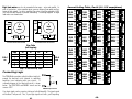
The PD5580 drive contains optical isolation circuitry to
prevent the electrical noise inherent in switching
amplifiers from interfering with your circuits. A
schematic diagram of the step input circuit is shown
below. The DIRECTION and ENABLE circuits are the
same as STEP.
680
0.1
3.8 0.2
0.4
AMPS/ 0.8
PHASE 1.6
1.9
0.1
4.4 0.2
0.4
AMPS/ 0.8
PHASE 1.6
1.9
0.1
4.9 0.2
0.4
AMPS/ 0.8
PHASE 1.6
1.9
0.1
5.0 0.2
0.4
AMPS/ 0.8
PHASE 1.6
1.9
PD5580 Input Circuit
Your logic signals can be sourcing, sinking or both (differential). The input current
will be about 1 mA per volt. Thus, if your logic signals are 5 volts, you'll be putting
-8-
-13-
2 3 4 5 6 7
Connecting Logic
0.1
4.3 0.2
0.4
AMPS/ 0.8
PHASE 1.6
1.9
2 3 4 5 6 7
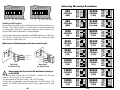
Step 2 is the Power Up State
0.1
3.7 0.2
0.4
AMPS/ 0.8
PHASE 1.6
1.9
2 3 4 5 6 7
DIR=0
ccw
2 3 4 5 6 7
B–
+
+
–
–
2 3 4 5 6 7
B+
+
–
–
+
+
0.1
5.4 0.2
0.4
AMPS/ 0.8
PHASE 1.6
1.9
0.1
5.5 0.2
0.4
AMPS/ 0.8
PHASE 1.6
1.9
2 3 4 5 6 7
A–
–
+
+
–
0.1
4.8 0.2
0.4
AMPS/ 0.8
PHASE 1.6
1.9
2 3 4 5 6 7
A+
+
+
–
–
+
0.1
4.2 0.2
0.4
AMPS/ 0.8
PHASE 1.6
1.9
0.1
5.3 0.2
0.4
AMPS/ 0.8
PHASE 1.6
1.9
2 3 4 5 6 7
DIR=1
cw
Step
0
1
2
3
4
0.1
3.6 0.2
0.4
AMPS/ 0.8
PHASE 1.6
1.9
0.1
5.2 0.2
0.4
AMPS/ 0.8
PHASE 1.6
1.9
2 3 4 5 6 7
Step Table
(full stepping)
0.1
5.1 0.2
0.4
AMPS/ 0.8
PHASE 1.6
1.9
2 3 4 5 6 7
8 Leads Parallel Connected
2 3 4 5 6 7
8 Leads Series Connected
Red/Wht B–
0.1
4.7 0.2
0.4
AMPS/ 0.8
PHASE 1.6
1.9
2 3 4 5 6 7
Yel/
B+ Wht
0.1
4.1 0.2
0.4
AMPS/ 0.8
PHASE 1.6
1.9
2 3 4 5 6 7
Yel/
Wht B–
0.1
3.5 0.2
0.4
AMPS/ 0.8
PHASE 1.6
1.9
2 3 4 5 6 7
Yellow
0.1
4.6 0.2
0.4
AMPS/ 0.8
PHASE 1.6
1.9
2 3 4 5 6 7
B+
Red/
Wht
Yel
low
0.1
4.5 0.2
0.4
AMPS/ 0.8
PHASE 1.6
1.9
2 3 4 5 6 7
Red
Black
Red
2 3 4 5 6 7
Black
0.1
4.0 0.2
0.4
AMPS/ 0.8
PHASE 1.6
1.9
2 3 4 5 6 7
Org/
Wht
A–
0.1
3.4 0.2
0.4
AMPS/ 0.8
PHASE 1.6
1.9
8
lead
motor
2 3 4 5 6 7
Blk/Wht
A–
Blk/Wht
8
lead
motor
Org/Wht
Orange
2 3 4 5 6 7
A+
0.1
3.9 0.2
0.4
AMPS/ 0.8
PHASE 1.6
1.9
2 3 4 5 6 7
Orange
0.1
3.3 0.2
0.4
AMPS/ 0.8
PHASE 1.6
1.9
2 3 4 5 6 7
A+
Current Setting Table, Part 2 (3.3 - 5.5 amps/phase)
2 3 4 5 6 7
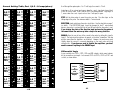
Eight lead motors can also be connected in two ways: series and parallel. As
with six lead motors, series operation gives you more torque at low speeds and less
torque at high speeds. In series operation, the motor should be operated at 30%
less than the rated current to prevent overheating. The wiring diagrams for eight
lead motors are shown below.