1
EXAMPLE: CREATING A MODEL OF AN OVERHEAD HOIST
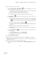
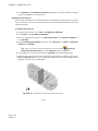
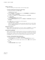
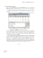
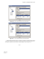
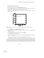
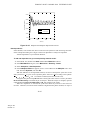
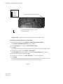
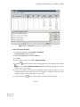
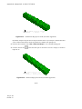
5. Accept the default selection of FrameSection, and click OK.
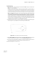
Abaqus/CAE assigns the truss section to the frame, colors the entire frame aqua to indicate that
the region has a section assignment, and closes the Edit Section Assignment dialog box.
2.3.5
Defining the assembly
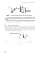
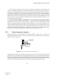
Each part that you create is oriented in its own coordinate system and is independent of the other parts
in the model. Although a model may contain many parts, it contains only one assembly. You define the
geometry of the assembly by creating instances of a part and then positioning the instances relative to
each other in a global coordinate system. An instance may be independent or dependent. Independent
part instances are meshed individually, while the mesh of a dependent part instance is associated with
the mesh of the original part. For further details, see “Working with part instances,” Section 13.3 of the
Abaqus/CAE User’s Manual. By default, part instances are dependent.
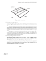
For this problem you will create a single instance of your overhead hoist. Abaqus/CAE positions
the instance so that the origin of the sketch that defined the frame overlays the origin of the assembly’s
default coordinate system.
To define the assembly:
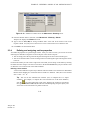
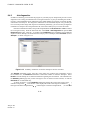
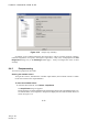
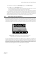
1. In the Model Tree, expand the Assembly container and double-click Instances in the list that
appears.
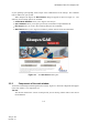
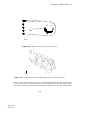
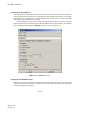
Abaqus/CAE switches to the Assembly module, and the Create Instance dialog box appears.
2. In the dialog box, select Frame and click OK.
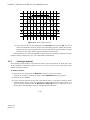
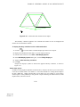
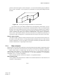
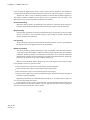
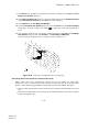
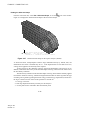
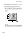
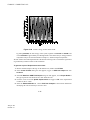
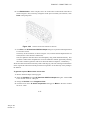
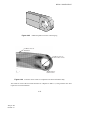
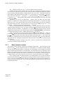
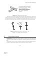
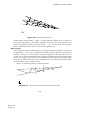
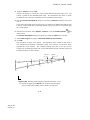
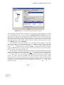
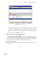
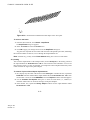
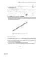
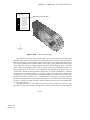
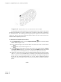
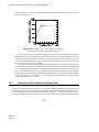
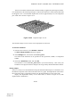
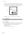
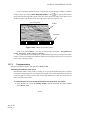
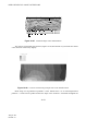
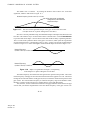
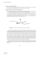
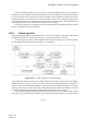
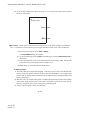
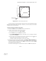
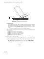
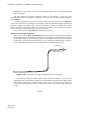
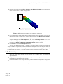
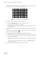
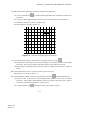
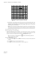
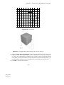
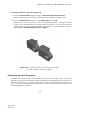
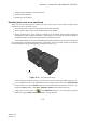
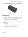
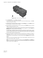
Abaqus/CAE creates an instance of the overhead hoist. In this example the single instance of the
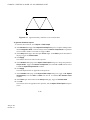
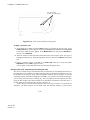
frame defines the assembly. The frame is displayed in the 1–2 plane of the global coordinate system (a
right-handed, rectangular Cartesian system). A triad in the lower-left corner of the viewport indicates
the orientation of the model with respect to the view. A second triad in the viewport indicates the origin
and orientation of the global coordinate system (X-, Y-, and Z-axes). The global 1-axis is the horizontal
axis of the hoist, the global 2-axis is the vertical axis, and the global 3-axis is normal to the plane of the
framework. For two-dimensional problems such as this one Abaqus requires that the model lie in a plane
parallel to the global 1–2 plane.
2.3.6
Configuring your analysis
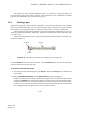
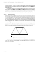
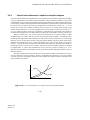
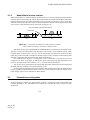
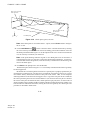
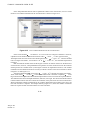
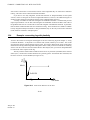
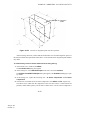
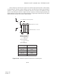
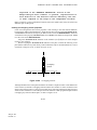
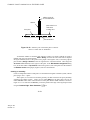
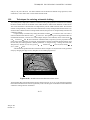
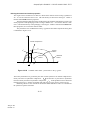
Now that you have created your assembly, you can configure your analysis. In this simulation we are
interested in the static response of the overhead hoist to a 10 kN load applied at the midspan, with the
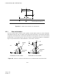
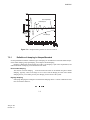
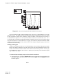
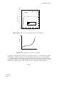
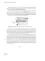
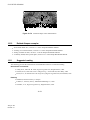
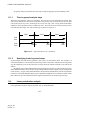
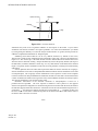
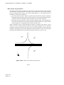
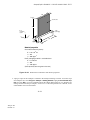
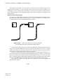
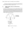
left-hand end fully constrained and a roller constraint on the right-hand end (see Figure 2–5). This is a
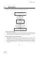
single event, so only a single analysis step is needed for the simulation. Thus, the model will consist of
two steps overall:
•
•
An initial step, in which you will apply boundary conditions that constrain the ends of the frame.
An analysis step, in which you will apply a concentrated load at the midspan of the frame.
2–23
Abaqus ID:
Printed on: