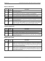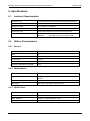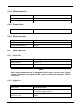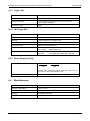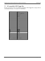
1
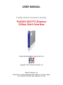
USER MANUAL ProDAQ VXI Data Acquisition Systems ProDAQ 3030 PCI Express VXIbus Slot-0 Interface PUBLICATION NUMBER: 3030-XX-UM-1010 Copyright, © 2014, Bustec Production, Ltd. Bustec Production, Ltd. Bustec House, Shannon Business Park, Shannon, Co. Clare, Ireland Tel: +353 (0) 61 707100, FAX: +353 (0) 61 707106 PROPRIETARY NOTICE This document and the technical data herein disclosed, are proprietary to Bustec Production Ltd., and shall not, without express written permission of Bustec Production Ltd, be used, in whole or in part to solicit quotations from a competitive source or used for manufacture by anyone other than Bustec Production Ltd. The information herein has been developed at private expense, and may only be used for operation and maintenance reference purposes or for purposes of engineering evaluation and incorporation into technical specifications and other documents, which specify procurement of products from Bustec Production Ltd. This document is subject to change without further notification. Bustec Production Ltd. Reserve the right to change both the hardware and software described herein. ProDAQ 3030 PCI Express VXIbus Slot-0 Interface User Manual 3030-XX-UM Table of Contents 1. INTRODUCTION .......................................................................................................... 7 1.1 Requirements ........................................................................................................ 7 1.1.1 The Host Computer ........................................................................................... 7 1.1.2 The ProDAQ 3261 PCI Express Host Interface Card ........................................ 7 1.1.3 The VXI Mainframe............................................................................................ 8 1.1.4 The ProDAQ 3030 PCI Express VXIbus Slot-0 Interface .................................. 8 1.1.5 The ProDAQ 8034 PCI Express x4 Cable ......................................................... 8 2. INSTALLATION ........................................................................................................... 9 2.1 Unpacking and Inspection ..................................................................................... 9 2.2 Installing the ProDAQ 3261 PCI Express Interface Card ....................................... 9 2.3 Software Installation ............................................................................................ 12 2.4 Installing the ProDAQ 3030 Interface .................................................................. 16 2.5 Connecting the ProDAQ 3030 to the Host Computer .......................................... 17 2.6 Assigning Interface Names .................................................................................. 19 2.7 Verifying the Installation ...................................................................................... 21 2.7.1 Running the VXIbus Resource Manager ......................................................... 21 3. SYSTEM CONFIGURATION ...................................................................................... 25 3.1 Configuring the ProDAQ 3261 Adapter Card ....................................................... 25 3.1.1 Theory of operation ......................................................................................... 25 3.1.2 The Configuration Dialog ................................................................................. 27 3.1.3 Applying the new Configuration ....................................................................... 30 3.2 Configuring the ProDAQ 3030 Interface .............................................................. 31 3.2.1 Configuring the VXIbus Access ....................................................................... 31 3.2.2 Configuring the LXI Trigger Bus (-AB version only) ......................................... 32 3.2.3 Configuring the Front Panel I/O ....................................................................... 33 4. THE PRODAQ 3030 SOFT FRONT PANEL APPLICATION ..................................... 35 4.1 CLK10 Configuration ........................................................................................... 36 4.2 Trigger Configuration, Control and Monitoring ..................................................... 36 4.2.1 Trigger Routing ................................................................................................ 36 4.2.2 LXI Trigger Mode (-Bx versions only) .............................................................. 36 4.2.3 Trigger Control ................................................................................................ 37 4.2.4 Trigger Monitoring ........................................................................................... 37 4.3 Identification ........................................................................................................ 37 5. VXIBUS REGISTER MAP .......................................................................................... 39 5.1 5.2 6. Address Map ....................................................................................................... 39 Register Description ............................................................................................ 39 SPECIFICATIONS...................................................................................................... 41 6.1 Interface Characteristics ...................................................................................... 41 6.2 VXIbus Characteristics ........................................................................................ 41 6.2.1 General............................................................................................................ 41 6.2.2 VXIbus Master ................................................................................................. 41 Copyright, © 2010-2014 Bustec Production Ltd. Page 3 of 52 3030-XX-UM ProDAQ 3030 PCI Express VXIbus Slot-0 Interface User Manual 6.2.3 VXIbus Slave ................................................................................................... 41 6.2.4 VXIbus Requester ........................................................................................... 42 6.2.5 VXIbus Arbiter ................................................................................................. 42 6.2.6 VXIbus Interrupts ............................................................................................. 42 6.3 Front Panel I/O .................................................................................................... 42 6.3.1 CLK10 I/O........................................................................................................ 42 6.3.2 Trigger In ......................................................................................................... 42 6.3.3 Trigger Out ...................................................................................................... 43 6.3.4 LXI Trigger Bus ............................................................................................... 43 6.3.5 Power Supply Loading..................................................................................... 43 6.4 Miscellaneous ...................................................................................................... 43 7. FRONT PANEL CONTROLS ..................................................................................... 45 7.1 7.2 7.3 Status LEDs......................................................................................................... 45 PCI Express Uplink/Downlink .............................................................................. 48 LXI compatible LVDS Trigger Bus ....................................................................... 49 Page 4 of 52 Copyright, © 2010-2014 Bustec Production Ltd. ProDAQ 3030 PCI Express VXIbus Slot-0 Interface User Manual 3030-XX-UM Table of Figures Figure 1 - PCI Express Slot Types ..................................................................................... 10 Figure 2 - ProDAQ 3261 Installation .................................................................................. 10 Figure 3 - Device Manager Display after 3261 Installation................................................. 11 Figure 4 – ProDAQ 3261 Status LEDs............................................................................... 11 Figure 5 - Device Manager Display after Driver Installation ............................................... 15 Figure 6 - Installing the ProDAQ 3030 into a C-Size Mainframe ........................................ 16 Figure 7 - Connecting the PCI Express Cable to the ProDAQ 3261 .................................. 17 Figure 8 - Unplugging a PCI Express Cable Connector ..................................................... 17 Figure 9 - Connecting the (first) ProDAQ 3030 .................................................................. 18 Figure 10 - Daisy-chain Configuration................................................................................ 18 Figure 11 - VISA Library Configuration Utility .................................................................... 20 Figure 12 - Add New Interface Dialog ................................................................................ 20 Figure 13 – Displaying known Interfaces ........................................................................... 21 Figure 14 - Running the VXI Resource Manager ............................................................... 21 Figure 15 - Resource Manager Configuration ................................................................... 22 Figure 16 - ProDAQ 3261/ProDAQ 3030 System Overview .............................................. 25 Figure 17 - VISA Library Configuration Utility .................................................................... 27 Figure 18 - Adapter Configuration Dialog........................................................................... 27 Figure 19 - Adapter Configuration with three Devices ....................................................... 29 Figure 20 - Adapter Configuration with different Number of Devices ................................. 29 Figure 21 - The ProDAQ 3030 Configuration Dialog .......................................................... 31 Figure 22 - LXI Trigger Configuration ................................................................................ 32 Figure 23 - Configuring the Front Panel I/O ....................................................................... 34 Figure 24 - ProDAQ 3030 Soft Front Panel Application ..................................................... 35 Figure 25 - Soft Front Panel About Dialog ......................................................................... 38 Figure 26 - ProDAQ 3030-AA Front Panel Connectors and Switches ............................... 46 Figure 27 - ProDAQ 3030-AB Front Panel Connectors and Switches ............................... 47 Copyright, © 2010-2014 Bustec Production Ltd. Page 5 of 52 3030-XX-UM ProDAQ 3030 PCI Express VXIbus Slot-0 Interface User Manual This page was intentionally left blank. Page 6 of 52 Copyright, © 2010-2014 Bustec Production Ltd. ProDAQ 3030 PCI Express VXIbus Slot-0 Interface User Manual 3030-XX-UM 1. Introduction PCI Express, the third-generation input/output standard, provides performance for peripheral devices beyond that of the older Peripheral Component Interconnect (PCI) and PCI Extended (PCI-X) busses. The higher performance of PCI Express derives from its faster, serial-bus architecture, which provides dedicated, bi-directional I/O links to devices with 2.5 GHz (GEN1) or 5 GHz (GEN2) clocking, versus the slower 133 MHz parallel bus of PCI-X. The ProDAQ 3030 PCI Express VXIbus Slot-0 Interface utilizes a four lane (x4) cable connection as defined in the PCI Express® External Cabling Specification to provide a link between the VXIbus and the host computer. In the host computer the ProDAQ 3261 PCI Express Host Interface Card provides the necessary cable connector and switch to connect the external cable to the computer’s PCI Express link. This manual describes the implementation, configuration and use of the ProDAQ 3030 PCI Express VXIbus Slot-0 Interface and the ProDAQ 3261 PCI Express Host Interface Card. 1.1 Requirements To set up and use the ProDAQ 3261 PCI Express Host Interface Card and the ProDAQ 3030 PCI Express VXIbus Slot-0 Interface, you need the following: A PC compatible computer with o Windows XP® 32-bit; or Windows 7®, 32-bit or 64-bit o a free PCI Express x4, x8 or x16 slot The ProDAQ 3261 PCI Express Host Interface Card A VXI mainframe The ProDAQ 3030 PCI Express VXIbus Slot-0 Interface A ProDAQ 8034 PCI Express x4 Cable ProDAQ Driver CD 1.1.1 The Host Computer The ProDAQ 3261 Host Interface Card together with the ProDAQ 3030 Slot-0 Interface allows your host computer to perform as if it is plugged directly into the VXI backplane. You will need one empty PCI Express expansion slot to install the ProDAQ 3261 into it. The ProDAQ 3261 needs in minimum a PCI Express slot with four lanes (x4), it cannot be installed in a one lane slot (x1). If you install it in an eight or sixteen lane slot (x8 / x16), the additional lanes will be ignored. The software currently supports Windows XP (and Windows 7, both in 32-bit or 64-bit versions. It is recommended to have the latest service pack installed. 1.1.2 The ProDAQ 3261 PCI Express Host Interface Card The ProDAQ 3261 is a standard height, half length PC add-in card. It interfaces a four lane PCI Express expansion slot to the four lane PCI Express External Cabling port via a nontransparent PCI Express switch, enabling devices connected via the cable port to be power-cycled and plug/unplugged without influencing the host computers operations. Copyright, © 2010-2014 Bustec Production Ltd. Page 7 of 52 3030-XX-UM ProDAQ 3030 PCI Express VXIbus Slot-0 Interface User Manual 1.1.3 The VXI Mainframe The ProDAQ 3030 PCI Express VXIbus Slot-0 Interface is a single-slot wide, C-size VXI module, which needs to be installed in the left most slot of the mainframe (slot “0”). Installing it into any other slot is not recommended, as the signals it generates might generate conflicts with any slot-0 controller installed in the same mainframe. The ProDAQ 3030 was designed according to the VXIbus standard VXI-1 Revision 4.0. It features the 160-pin VXIbus connectors introduced in this revision of the standard and supports the new, high-speed synchronization clock as well as the faster transfer modes like 2eVME and 2eSST. If you install it in a VXIbus mainframe with a backplane featuring the 96-pin connectors of the previous VXIbus revisions, some these features will not be supported. All other functionalities will not be affected, i.e. the ProDAQ 3030 will support all functionalities already defined in the previous revisions of the VXIbus standard. Note If you install the ProDAQ 3030 in a VXIbus mainframe equipped with a backplane compatible to earlier revisions of the VXIbus standard than Revision 4.0, it will only support signals and transfer modes already defined in these revisions. Signals like for example LSYNC100/LCLK100 or the 2eSST data transfer modes will not be supported. Note Being a C-size module, the ProDAQ 3030 does not provide a P3 connector as used in D-size mainframes. If used as a slot-0 controller in a D-size mainframe, it cannot provide the necessary control for instruments using the additional features of the P3 connector (CLK100, Star Trigger, add. Trigger and Local Bus Lines). 1.1.4 The ProDAQ 3030 PCI Express VXIbus Slot-0 Interface The ProDAQ 3030 PCI Express VXIbus Slot-0 Interface is a C-size, register based VXIbus module providing a direct link between the high-speed PCI Express bus and the VXI backplane. The PCI Express to VXIbus bridge in the ProDAQ 3030 allows for low-latency, memory-mapped single accesses as well as high-speed, block transfers controlled by the internal DMA machines. A build-in PCI Express switch allows connecting further ProDAQ 3030 controller in a daisy-chain configuration. In addition to the standard front-panel trigger and clock I/O an optional LXI compatible trigger interface allows the routing of the complete VXIbus trigger lines between multiple crates or to share them with other devices equipped with a similar trigger bus. 1.1.5 The ProDAQ 8034 PCI Express x4 Cable To connect the ProDAQ 3030 PCI Express VXIbus Slot-0 Interface to your host computer, the ProDAQ 8034 PCI Express x4 cable is available in different lengths up to 7 meter. Besides the signals that are required to transmit/receive data on the PCI Express interface, it also transmits signals that are necessary to implement the PCI Express interface in a distributed system environment like for example cable present detect, cable power on and a reference clock as defined in the PCI Express External Cabling standard. Page 8 of 52 Copyright, © 2010-2014 Bustec Production Ltd. ProDAQ 3030 PCI Express VXIbus Slot-0 Interface User Manual 3030-XX-UM 2. Installation To use the ProDAQ 3030 PCI Express VXIbus Slot-0 Interface to control your VXIbus mainframe(s), you need to install hard- and software into your system. To do so, use the installation sequence as described in this chapter: 2.1 Step 1: Unpacking and Inspection Step 2: Installing the ProDAQ 3261 Interface Card Step 3: Installing the VISA Library Step 4: Installing the ProDAQ 3030 Interface Step 5: Connecting the ProDAQ 3030 to the Host Computer Unpacking and Inspection All ProDAQ modules are shipped in an antistatic package to prevent any damage from electrostatic discharge (ESD). Proper ESD handling procedures must always be used when packing, unpacking or installing any ProDAQ module, ProDAQ plug-in module or ProDAQ function card: Ground yourself via a grounding strap or similar, e.g. by holding to a grounded object. Remove the ProDAQ module from its carton, preserving the factory packaging as much as possible. Discharge the package by touching it to a grounded object, e.g. a metal part of your VXIbus chassis, before removing the module from the package. Inspect the ProDAQ module for any defect or damage. Immediately notify the carrier if any damage is apparent. Only remove the module from its antistatic bag if you intend to install it into a VXI mainframe or similar. When reshipping the module, use the original packing material whenever possible. The original shipping carton and the instrument’s plastic foam will provide the necessary support for safe reshipment. If the original anti-static packing material is unavailable, wrap the ProDAQ module in anti-static plastic sheeting and use plastic spray foam to surround and protect the instrument. 2.2 Installing the ProDAQ 3261 PCI Express Interface Card To install the ProDAQ 3261 PCI Express Interface Card into your computer, you need first to switch it off, open its enclosure and locate a free PCI Express slot. The PCI Express slot needs to be either a x4, x8 or x16 slot to allow installation of the ProDAQ 3261 card (see Figure 1 – PCI Express Slot Types). The card cannot be installed in a x1 slot often found in older motherboards. If you use multiple PCI Express slots of the types x4, x8 or x16 on your motherboard, make sure that the total amount of PCI Express lanes used is still supported by your chipset. In some combinations slots may revert to x1 slots even while providing more connections on the connector. See your motherboard or PC documentation for details. Copyright, © 2010-2014 Bustec Production Ltd. Page 9 of 52 3030-XX-UM ProDAQ 3030 PCI Express VXIbus Slot-0 Interface User Manual PCI Express Connector, x16 PCI Express Connector, x1 PCI Express Connector, x4 PCI Express Connector, x8 Figure 1 - PCI Express Slot Types To install the ProDAQ 3261 card into your computer, slide it into the slot chosen and use a screw or the retention feature provided by your computer to fix the card’s I/O bracket in place: Use screw or available retention feature to fix the I/O bracket in place. Figure 2 - ProDAQ 3261 Installation Page 10 of 52 Copyright, © 2010-2014 Bustec Production Ltd. ProDAQ 3030 PCI Express VXIbus Slot-0 Interface User Manual 3030-XX-UM When you restart your computer after installing the ProDAQ 3261 Interface Card, the card will be visible in the device manager as “Other PCI Bridge Device” (see Figure 3) Figure 3 - Device Manager Display after 3261 Installation If you are encountering problems starting your computer after installing the 3261, you should check whether the PCI Express switch on the card could successfully establish a link to the PCI Express root complex in the computer. The LED indicating the link is located on the rear I/O bracket of the ProDAQ 3261 (see Figure 4, “Host Link”). If it is off, the PCI Express switch located on the 3261 was not able to establish the PCI Express link to the host. If it is blinking, a link with a speed of 2.5 GT/s (GEN1) was established, if it is on constantly, a link with a speed of 5 GT/s (GEN2) was established. Hot-plug/ Enumeration Status (green) Host Link (orange) Reset Button Figure 4 – ProDAQ 3261 Status LEDs Common problems after installing the ProDAQ 3261 are caused mainly by the way motherboard manufacturers have implemented the Spread Spectrum Clock for the PCI Express and the usage of PCI and PCI express resources in your computer. Copyright, © 2010-2014 Bustec Production Ltd. Page 11 of 52 3030-XX-UM ProDAQ 3030 PCI Express VXIbus Slot-0 Interface User Manual In the following table you may find a description of the error you are encountering and some recommendations to solve the problem. If none of the descriptions describe your problem and/or none of the recommendations solve the problem, please contact our support team at “[email protected]” for further assistance. Error Description Host Link Status Recommendation PC does not boot, no access to BIOS LED is off (no link) Remove 3261, boot your PC to access the BIOS settings, change setting for the spread spectrum clock (also called “SSC”) in the BIOS (disable it if it was enabled or vice versa) LED is on or blinking (link established) Remove all unnecessary peripheral or onboard devices to reduce resource usage on the PCI / PCI Express busses. Start by removing expansion cards, if the PC does still not boot, remove unnecessary motherboard devices by disabling them in the BIOS. LED is off (no link) Change setting for the spread spectrum clock (also called “SSC”) in the BIOS (disable it if it was enabled or vice versa) LED is on or blinking (link established) Remove all unnecessary peripheral or onboard devices to reduce resource usage on the PCI / PCI Express busses. Start by removing expansion cards, if the PC does still not boot, remove unnecessary motherboard devices by disabling them in the BIOS. PC boots normal, but no new “Other PCI bridge device” visible in the device manager The reset button allows you to boot the computer with a default setting for the ProDAQ 3261 once you may have changed its configuration (see chapter 3.1). To do so, keep it pressed while rebooting your computer. Release the button once you hear the beep signalizing the end of the POST phase of the BIOS boot process or when the operating system load process starts. WARNING Do not press the reset button on the ProDAQ 3261 during normal operation. To do so may damage the configurations stored on the card and may render it unusable. 2.3 Software Installation To use the ProDAQ 3261/3030 to access your VXI instruments, you must install the Bustec VISA library and the ProDAQ 3030 driver. Both can be found on our website under http://www.bustec.com/support/drivers/. The VISA library must be installed first, then the ProDAQ 3030 and any other hardware driver necessary for your system. For a description of the installation of the VISA library and tools please refer to the “Bustec VISA Library and Tools User Manual” (http://www.bustec.com/uploads/support/8200-XX-UM.pdf). Page 12 of 52 Copyright, © 2010-2014 Bustec Production Ltd. ProDAQ 3030 PCI Express VXIbus Slot-0 Interface User Manual 3030-XX-UM Note ® On Microsoft Windows XP , Microsoft Windows VISTA® or Microsoft Windows 7® systems it is recommended to install the VISA library and hardware drivers from an account having administrator privileges. To install the ProDAQ 3030 driver on your PC, do the following: 1. Apply power to your PC and boot your operating system. Close all open applications to allow for a safe installation of the new components. 2. Insert the driver CD provided with the module into your PC CD-ROM drive or, in case you downloaded the installation, extract the file(s) from the archive downloaded into a directory on your hard drive. To start the installation of the ProDAQ 3030 driver, start the executable Microsoft Installer package from the CD or the directory you extracted the installation file(s) into. 3. Select “Next” and agree to the license agreement. Select “Next” again. Copyright, © 2010-2014 Bustec Production Ltd. Page 13 of 52 3030-XX-UM ProDAQ 3030 PCI Express VXIbus Slot-0 Interface User Manual 4. Now the installation will ask you for the installation path. It is recommended to use the default location, which is determined by the VXIPNPPATH system variable. Select “Next” to continue. 5. Now the installer is ready to install the driver onto your PC. Please select “Install” to start the installation. As installation contains the device driver for the ProDAQ 3261/3030, you must accept to install the driver for the system to work properly: Page 14 of 52 Copyright, © 2010-2014 Bustec Production Ltd. ProDAQ 3030 PCI Express VXIbus Slot-0 Interface User Manual 3030-XX-UM 6. After the installation is completed, select “Finish” to exit the installer. The ProDAQ 3261 should now be visible in the device manager as a bridge device for the ProDAQ 3030 PCI Express VXIbus Slot-0 Controller: Figure 5 - Device Manager Display after Driver Installation Note: As the VISA Library is not designed to handle run-time power management events, you will need to prevent your computer to enter the standby (sleep) or hibernate power states while working with the ProDAQ 3261/ProDAQ 3030. To do so, open your control panel, select “Power Options” and change the settings for the “System standby” and “System hibernates” modes to “Never”. Copyright, © 2010-2014 Bustec Production Ltd. Page 15 of 52 3030-XX-UM 2.4 ProDAQ 3030 PCI Express VXIbus Slot-0 Interface User Manual Installing the ProDAQ 3030 Interface To prevent damage to the ProDAQ module being installed, remove the power from the mainframe or switch it off before installing. Insert the module into the mainframe using the guiding rails inside the mainframe as shown in Figure 10. Push the module slowly into the slot until the modules backplane connectors seat firmly in the corresponding backplane connectors. The top and bottom of the front panel of the module should touch the mounting rails in the mainframe. Front panel mounting screws Slide the module into the mainframe using the guiding rails until it connectors plug into the backplane connectors. Figure 6 - Installing the ProDAQ 3030 into a C-Size Mainframe Note: To ensure proper grounding of the module, tighten the front panel mounting screws after installing the module in the mainframe. Note: The ProDAQ 3030 PCI Express VXIbus Slot-0 Interface does not extend the VXI backplane between mainframes in a multi-mainframe system. This means that devices sharing the VXI local bus must be installed in the same mainframe. Page 16 of 52 Copyright, © 2010-2014 Bustec Production Ltd. ProDAQ 3030 PCI Express VXIbus Slot-0 Interface User Manual 2.5 3030-XX-UM Connecting the ProDAQ 3030 to the Host Computer To connect the ProDAQ 3030 PCI Express VXIbus Slot-0 Interface to your computer, use a ProDAQ 8034 PCI Express Cable. The cable is equipped with a connector featuring a push/pull lock mechanism. To connect the ProDAQ 3030 to your host computer, plug one end of the 8034 cable into the upper cable connector socket of the ProDAQ 3261 installed in your computer: Figure 7 - Connecting the PCI Express Cable to the ProDAQ 3261 Push the connector in firmly until the lock mechanism holds the connector in place. To unplug the connector, use the pull to release the lock mechanism and slide the connector out of the socket: Pull Figure 8 - Unplugging a PCI Express Cable Connector Copyright, © 2010-2014 Bustec Production Ltd. Page 17 of 52 3030-XX-UM ProDAQ 3030 PCI Express VXIbus Slot-0 Interface User Manual Connect the other end of the ProDAQ 8034 PCI Express cable to the uplink port of the ProDAQ 3030 installed into your VXI mainframe: Figure 9 - Connecting the (first) ProDAQ 3030 If you want to connect multiple ProDAQ 3030 to the same host computer, connect additional ProDAQ 3030 by daisy-chaining the downlink port of the already connected 3030 to the uplink port of the next 3030: Figure 10 - Daisy-chain Configuration Page 18 of 52 Copyright, © 2010-2014 Bustec Production Ltd. ProDAQ 3030 PCI Express VXIbus Slot-0 Interface User Manual 3030-XX-UM Note: In a daisy-chain configuration, each ProDAQ 3030 with devices connected to the downlink port must be powered on to allow the host PC access to these devices. Note: Due to the hot-plug capabilities of the 3261/3030 system, the PCI Express cables connecting the host computer to the mainframe(s) can be plugged and unplugged without powering off the VXI mainframe(s). Yet, if in a daisy-chain configuration a cable to a ProDAQ 3030, which has other 3030 connected to its downlink port, is unplugged and plugged in again without power cycling the mainframes, all systems on the downlink side will not be accessible anymore and will need to be powercycled or reset. Every time a connection is initiated by plugging in a cable or power-cycling a mainframe, the processor on the ProDAQ 3261 will establish the communication to the connected devices and enumerate them. During this time, the “Hot-plug/Enumeration Status” LED on the rear I/O bracket of the ProDAQ 3261 will blink. It will return to its default “on” state once all devices are enumerated. As a result, a PCI Express “Link” is established between the devices. The status of the link between the devices is indicated by LEDs on the frontpanel of the ProDAQ 3030 (see Figure 26 and Figure 27): Name Color Mode Description Link Green On Device enumerated. Green Blinking Device not enumerated Yellow On Link established, speed 5.0 GBit (GEN2) Yellow Blinking Link established, speed 2.5 GBit (GEN1) - Off no link PCIe SPD 2.6 Assigning Interface Names The VISA library uses interface names and numbers to access available hardware interfaces. In order to enable the VISA library to use a ProDAQ 3030 interface, which is connected to a host PC for the first time, a valid interface name and number must be assigned to this device. The assigned interface name and number will be stored internally in the configuration for this ProDAQ 3030 interface together with its serial number and will be used for this device whenever it is connected to this host. To assign an interface name/number and configure the ProDAQ 3030, connect the uplink port to the host PC or to the downlink port of a ProDAQ 3030 which is already connected to a daisy chain configuration with your host computer and turn on the VXI mainframe. Copyright, © 2010-2014 Bustec Production Ltd. Page 19 of 52 3030-XX-UM ProDAQ 3030 PCI Express VXIbus Slot-0 Interface User Manual From the Bustec VISA program group created during the installation of the VISA library, select “VISA Configuration Utility” (“Start” “Programs” “Bustec VISA” “VISA Configuration Utility”). This will start the configuration tool for the VISA library. Figure 11 - VISA Library Configuration Utility After start, it shows the list of adapter cards installed in your computer. Please check whether the ProDAQ 3261 you installed in the previous steps is visible. The ProDAQ 3261 is installed with a default configuration which will allow you to access the VXI instruments in your crate and should be sufficient for most applications. If your application has special requirements, you can change this configuration later by selecting the “Configure Adapter ...” button on the right (see 3.1). To add a new interface, select the “Interfaces” tab and click “Add Interfaces”. A new dialog “Add New Interface” is shown with a list of unconfigured devices found in the system. ProDAQ 3030 interfaces appear as interfaces of the type “VXI” together with a description containing the serial number of the device. Figure 12 - Add New Interface Dialog To configure and add a ProDAQ 3030 interface, select the entry for the device in the list, choose an interface number on the right side and select ‘OK’. The list of configured interfaces in the main dialog will now display the newly added interface with its interface name and number: Page 20 of 52 Copyright, © 2010-2014 Bustec Production Ltd. ProDAQ 3030 PCI Express VXIbus Slot-0 Interface User Manual 3030-XX-UM Figure 13 – Displaying known Interfaces To remove the configuration for a device from the system, select the device in the list of known interfaces and select “Remove Interface”. To configure device-dependent parameters of an interface, select “Configure Interface”. If you want to access a hot-plug device which was not connected when the configuration utility was started, but was already added on this system, the “Refresh List” button can be used to update the list of known interfaces. 2.7 Verifying the Installation Once you have completed the installation as described above, you can verify the installation by using the tools supplied with the VISA library and by installing VXIplug&play drivers and running the instruments soft front panels or by running your application. 2.7.1 Running the VXIbus Resource Manager Before you can use the VISA library to communicate to the instruments, you must run the resource manager. The resource manager searches for VXI GPIB instruments connected to your PC and configure them. To run the resource manager, select “VXIbus Resource Manager” from the Bustec VISA program group in the start menu (“Start” “Programs” “Bustec VISA” ”VXI Resource Manager”) or click on the desktop icon. Figure 14 - Running the VXI Resource Manager After start, the resource manager will wait a defined time to allow all devices to complete their initialization and self-test (if available). Then he performs the following functions: Copyright, © 2010-2014 Bustec Production Ltd. Page 21 of 52 3030-XX-UM ProDAQ 3030 PCI Express VXIbus Slot-0 Interface User Manual 1. 2. 3. 4. 5. 6. Identify all VXIbus devices in the system. Manage the system self-test and diagnostic sequence. Configure the system’s A24 and A32 address maps. Configure the system’s Commander/Servant hierarchies. Allocate the VXIbus IRQ lines. Initiate normal system operation. Once finished, the information about the VXIbus devices found is made available for the VISA library and a readable version of this information is saved to a file. Both the initial delay and the location of the resource manager output file are configurable using the configuration utility. To configure these parameters, start the configuration utility by selecting the “VISA Configuration Utility” entry in the Bustec VISA program group in the start menu (“Start” “Programs” “Bustec VISA” ”VISA Configuration Utility”). In the configuration utility, select the “Interfaces tab” and then the “Resource Manager” button on the right hand side (see Figure 13). This will show the configuration dialog for the resource manager, which allows configuring the output file destination and initial delay. Figure 15 - Resource Manager Configuration Note To run the resource manager for a VXI mainframe connected via a ProDAQ 3030 PCI Express VXIbus Slot-0 Interface to your computer, the ProDAQ 3030 must be located in the left most slot (slot “0”) of the VXI mainframe and must be configured to use the logical address 0 (00hex). Note Although the ProDAQ 3030 PCI Express VXIbus Slot-0 Interface can be hotplugged, the resource manager cannot dynamically add or remove devices from its device list. Therefore the resource manager must be run every time a VXI mainframe is connected/disconnected to/from your computer or power-cycled while being connected to your computer. There is also no protocol available to notify applications of the configuration change. Running applications must be restarted after re-running the resource manager. Page 22 of 52 Copyright, © 2010-2014 Bustec Production Ltd. ProDAQ 3030 PCI Express VXIbus Slot-0 Interface User Manual 3030-XX-UM Caution The initial resource manager delay as defined by the VXIbus standard must be in minimum five (5) seconds. Configuring the resource manager to use a shorter delay might not allow all devices to finish their initialization and self-test, preventing the resource manager from identifying and configuring them. Note The VISA library is a shared library that initializes itself when it is first loaded by an application. Applications started while the VISA library is already loaded just share this configuration. Only when all applications using the VISA library are stopped, it will be unloaded by the system. Therefore all applications using the VISA library must be closed before running the resource manager or using the VISA configuration utility. Take special care while using integrated development environments, they will keep the VISA library loaded even when the application developed in them was stopped. Copyright, © 2010-2014 Bustec Production Ltd. Page 23 of 52 3030-XX-UM ProDAQ 3030 PCI Express VXIbus Slot-0 Interface User Manual This page was intentionally left blank. Page 24 of 52 Copyright, © 2010-2014 Bustec Production Ltd. ProDAQ 3030 PCI Express VXIbus Slot-0 Interface User Manual 3030-XX-UM 3. System Configuration The ProDAQ 3261 adapter cards and the ProDAQ 3030 slot-0 interfaces are shipped with a default configuration targeted to work with most applications. It is recommended to apply changes to this configuration only if your application requires them, as some configurations might render your system unusable. 3.1 Configuring the ProDAQ 3261 Adapter Card The ProDAQ 3261 adapter card makes it possible to hot-plug/hot power-cycle ProDAQ 3030 interfaces by providing a fixed PCI Express endpoint to the host system and translating all accesses to the interfaces through this endpoint. Depending on your application and the way it accesses the VXIbus instruments, you may need to optimize the configuration of this endpoint and the translation performed. 3.1.1 Theory of operation Registers System Page Cust. Page 1 Cust. Page 2 Cust. Page N VXIbus Addr. Spaces A16/A24/A32/A64 ProDAQ 3030 #1 ProDAQ 3030 #2 Registers System Page Cust. Page 1 Cust. Page 2 Cust. Page N ProDAQ 3030 #N Address Space in Host Computer allocated by ProDAQ 3261 VISA Hardware Interface External PCI Express Address Space The ProDAQ 3261 interface card allocates a fixed area in the host computers address range and maps it to the address space used on the external PCI Express busses to give the host computer access to the devices – the ProDAQ 3030 interfaces - there. Each of the ProDAQ 3030 then uses its part of the address space on the external PCI Express busses to map parts of the VXIbus address spaces into it – thus giving the host computer access to the VXIbus instruments. Registers System Page Cust. Page 1 Cust. Page 2 Cust. Page N Figure 16 - ProDAQ 3261/ProDAQ 3030 System Overview To configure the system correctly, it is necessary to understand how the application uses the VISA library to access the VXIbus instruments. Copyright, © 2010-2014 Bustec Production Ltd. Page 25 of 52 3030-XX-UM ProDAQ 3030 PCI Express VXIbus Slot-0 Interface User Manual The VISA library offers a number of different ways to access VXIbus instruments. From the point of view of the hardware interface, they fall into three categories: 1. Single register accesses using VISA library functions This are all accesses to VXIbus instruments using VISA library functions like viRead() / viWrite() and all functions based on them (e.g. viWriteAsync(), viPrintf(), viQueryf(), etc.), as the word serial protocol is implemented by reading/writing to the communication registers of a message based device; and all viInXX() / viOutXX() functions. 2. Single register accesses using mapped address areas This are all accesses performed directly to address spaces of VXIbus instruments mapped into the host computers address space by using the VISA library functions viMapAddress() / viMapAddressEx(); either by using the VISA library functions/macros viPeekXX() / viPokeXX() or direct program access (e.g. by using pointers). 3. Block moves using VISA library functions last not least are all access moving blocks of data using the VISA library functions like viMoveInXX(), viMoveOutXX(), viMove(), etc. To perform accesses of the types 1 and 3 (single accesses and block moves using VISA library functions), the ProDAQ 3261/ProDAQ 3030 driver inside the VISA library needs access to the ProDAQ 3030 registers and the system page. The system page is a relatively small area which is used to access directly the VXIbus address spaces under driver control, while the registers are used for configuration and for example to set up DMA machines for the block moves etc. These two spaces need to be mapped by the ProDAQ 3261 into the host address space (see Figure 16). To perform accesses of type 2 (accesses using mapped address spaces) each ProDAQ 3030 has additional address pages, which can be used separately or combined to map portions of the VXIbus address space A16/A24/A32 and A64. The more PCI Express address space per ProDAQ 3030 is allocated, the more custom pages for mapping address space using viMapAddress() and/or viMapAddressEx() are available. To allow full VISA functionality, the default configuration PCI Express endpoint of the ProDAQ 3261 adapter by default allocates and maps not only enough address space to allow access to these two spaces for the maximum number of ProDAQ 3030 interfaces to be connected to each of its ports, but also some extra space to allow further mapping via viMapAddress() and/or viMapAddressEx(). Page 26 of 52 Copyright, © 2010-2014 Bustec Production Ltd. ProDAQ 3030 PCI Express VXIbus Slot-0 Interface User Manual 3030-XX-UM 3.1.2 The Configuration Dialog To configure a ProDAQ 3261 adapter, you must run the VISA Configuration Utility. From the Bustec VISA program group created during the installation of the VISA library, select “VISA Configuration Utility” (“Start” “Programs” “Bustec VISA” “VISA Configuration Utility”). This will start the configuration tool for the VISA library. Figure 17 - VISA Library Configuration Utility After start, it shows the list of adapter cards installed in your computer. Select the adapter in the list you want to configure and then click on the “Configure Adapter ...” button on the right side. Figure 18 - Adapter Configuration Dialog Copyright, © 2010-2014 Bustec Production Ltd. Page 27 of 52 3030-XX-UM ProDAQ 3030 PCI Express VXIbus Slot-0 Interface User Manual The dialog shows the configuration of the address space allocation performed by the ProDAQ 3261 and its distribution between the two possible PCI Express chains and the ProDAQ 3030 interfaces in them. The top slider (“Host address space size”) shows the total amount of memory allocated by the ProDAQ 3261 in the host address space for being mapped onto the external PCI Express address space, while the two sliders below allow configuring the number of ProDAQ 3030 interfaces which are possible to connect to each chain. The actual configuration is shown graphically as list of actual devices detected (showing the interface model and serial number; see Figure 19, Chain “A”, first two devices) or reserved address spaces per chain (displaying “No device detected”). All ProDAQ 3030 in one chain have to have the same amount of memory allocated; it is not possible to allocate in the same chain different address ranges per ProDAQ 3030. But it is possible to allocate different sizes of address ranges for the devices in chain “A” and chain “B”, so the last parameter “Address space distribution” allows you to select which chain shall receive which amount of the address space selected by the top slider in case the selected address space size and number of devices in chain “A” and “B” allow for multiple combinations. The default configuration (see Figure 18) reserves 32 Mbytes in the host address space and allows connecting up to four ProDAQ 3030 interfaces per chain at the same time. Each ProDAQ 3030 interface then has its own address space of 4 Mbytes allocated inside this space to allow the mentioned general access and some mapping. In fact, the general access uses only 64 Kbytes out of the reserved space per ProDAQ 3030, so that using the default configuration allows mapping up to 4032 Kbytes per VXIbus crate of the instruments address spaces into the application. To increase this size to allow bigger VXIbus address spaces to be mapped into the application, you can now either move the top slider to the right, so that the ProDAQ 3261 adapter allocates more memory which is then distributed to the ProDAQ 3030 interfaces, or move the bottom two sliders to the left to decrease the number of ProDAQ 3030 which can be connected to each port of the ProDAQ 3261. To decrease the size and/or number of devices per chain, move the sliders to the left. The size of the allocated address spaces for both the host address space and the ProDAQ 3030 address space is selectable between 4 and 256 Mbytes (4, 8, 16, 32, 64, 128 or 256 Mbytes), so that it is possible to select a variety of combinations to adapt for any given situation. As the amount of host address space which can be allocated by the ProDAQ 3261 depends on the actual hardware configuration of the host PC and its BIOS settings, it is recommended to start off by calculating the amount of address space mapping needed for the overall system and choosing the minimal amount of address space allocation in the host which allows this. Figure 19 and Figure 20 show two examples with modified configurations. In the configuration shown in Figure 19 the ProDAQ 3261 will allocate 64 Mbytes of the host address space to map it to the ProDAQ 3030 interfaces in the external PCI Express address space. Because the number of devices per chain is set to allow a maximum of three ProDAQ 3030 per chain, the 64 Mbytes can be either distributed evenly into 8 Mbytes per ProDAQ 3030; or one chain can be selected to receive a bigger portion of the address space so that the distribution becomes one chain with three ProDAQ 3030 each havening 16 Mbytes allocated for and the other chain with three ProDAQ 3030 each having 4 Mbytes allocated for. Page 28 of 52 Copyright, © 2010-2014 Bustec Production Ltd. ProDAQ 3030 PCI Express VXIbus Slot-0 Interface User Manual 3030-XX-UM Figure 19 - Adapter Configuration with three Devices and 8 Mbytes Address Space per Device Figure 20 - Adapter Configuration with different Number of Devices and Address Space Size per Chain Copyright, © 2010-2014 Bustec Production Ltd. Page 29 of 52 3030-XX-UM ProDAQ 3030 PCI Express VXIbus Slot-0 Interface User Manual 3.1.3 Applying the new Configuration To apply the new configuration, click the “Ok” button on the dialog. If you have made changes to the host address space size, you will need to also close the Configuration Utility and reboot the host computer. After the restart you can use the adapter configuration dialog again to check the existing configuration. If you have only changed the number of ProDAQ 3030 interfaces per chain or the memory distribution between the chains, you only need to re-run the VXIbus Resource Manager after closing the Configuration Utility. If you have increased the “Host address space size”, the BIOS of the host computer may not longer be able to fit the ProDAQ 3261 together with the other PCI / PCI Express resources in the host computers address space. As a result the computer might not longer boot or, if the computer still boots as normal, the ProDAQ 3261 may not longer be visible. In this case you can use the reset button on the ProDAQ 3261 to boot the host computer with a minimal configuration. Keep it pressed while rebooting the computer. Release the button once you hear the beep signalizing the end of the POST phase of the BIOS boot process, or, when this signal is not available, latest when the operating system starts its load process. WARNING Do not press the reset button on the ProDAQ 3261 except during boot time. Using the button during normal operation might damage the configurations stored and render the card unusable. The minimal configuration the ProDAQ 3261 uses when booted while the reset button is pressed can only be used to enable the computer to boot correctly. To restore your system into a working condition, you must use the configuration utility again to assign the configuration used before or any other known working configuration and reboot again. WARNING The minimal configuration used when booting the system while pressing the reset button on the ProDAQ 3261 cannot be used for normal operation. A known good configuration needs to be assigned and the computer rebooted before continuing. Page 30 of 52 Copyright, © 2010-2014 Bustec Production Ltd. ProDAQ 3030 PCI Express VXIbus Slot-0 Interface User Manual 3.2 3030-XX-UM Configuring the ProDAQ 3030 Interface The ProDAQ 3030 PCI Express VXIbus Slot-0 Interface has a number of characteristics that can be configured with the configuration utility. The settings are stored together with the device name/number and the serial number on the host system and applied whenever the device is connected to the host system and the resource manager is executed. To configure the ProDAQ 3030, select the device you want to configure in the list and select “Configure Interface”. The three tab panels of the configuration dialog allow configuring the different parts of the interface: VXIbus Configures various parameters used by the ProDAQ 3030 when accessing the VXIbus. LXI Triggers Configures the routing of the TTL backplane trigger lines to/from the front panel LXI trigger bus. Front Panel I/O Configures the routing of VXIbus clock and trigger lines to/from the front panel connectors. Figure 21 - The ProDAQ 3030 Configuration Dialog To store the altered configuration, select “OK”. “Cancel” closes the dialog without altering the stored configuration. . 3.2.1 Configuring the VXIbus Access To configure the VXIbus access of the ProDAQ 3030 interface selected, select the tab “VXIbus” in the configuration dialog window (see Figure 18). The configurable parameters are: Copyright, © 2010-2014 Bustec Production Ltd. Page 31 of 52 3030-XX-UM ProDAQ 3030 PCI Express VXIbus Slot-0 Interface User Manual Bus Timeout The time the on-board times needs to expire once a VXIbus access by the 3030 is started. If it expires, a VXIbus slave did not respond correctly and a bus error is generated. Possible values are: 16 µsec, 32 µsec, 64 µsec, 128 µsec, 256 µsec, 512 µsec, 1025 µsec and 2048 µsec. Arbitration Mode Selects the bus arbiter mode. Possible values are: “PRI” (Priority), “SGL” (Single) and “RRS” (Round Robin). Request Mode Sets the request mode of the ProDAQ 3030. Possible values are “Demand” or “Fair”. Release Mode Selects the release mode for the ProDAQ 3030. Possible values are “ROR” (Release on Request) or “RWD” (Release when Done). 3.2.2 Configuring the LXI Trigger Bus (-AB version only) To configure the front panel LXI-compatible LVDS Trigger bus, select the “LXI Triggers” tab in the ProDAQ 3030 configuration dialog. Figure 22 - LXI Trigger Configuration The parameters for each trigger line are: Mapping Page 32 of 52 Selects the direction in which the VXIbus TTL trigger lines are mapped to the front panel LXI trigger lines. Possible values are: “Disconnected”, “LXI -> TTL” and “TTL -> LXI”. Copyright, © 2010-2014 Bustec Production Ltd. ProDAQ 3030 PCI Express VXIbus Slot-0 Interface User Manual 3030-XX-UM Driver Mode Selects the operation mode of the LXI trigger bus drivers. The driver mode can be either “Disabled”, “Driven” or “Wired-Or”. Bias When in wired-or mode, the driver can be set to provide the bias for all connected drivers. Check the checkbox to enable bias generation, uncheck the box to disable bias generation. In addition to configuring, the dialog allows to control the LXI trigger lines and to monitor their status. Via the “Control” selection the lines can be individually asserted or de-asserted. The Status LEDs show the actual status of the corresponding line. The status is updated every 0.5 s. 3.2.3 Configuring the Front Panel I/O The ProDAQ 3030 PCI Express VXIbus Slot-0 Interface supports the synchronization of multi-mainframe systems via shared system clocks (CLK10) and trigger lines. To configure the front panel input and output signals, select the “Front Panel I/O” tab on the right hand side of the configuration utility window (see Figure 23). If the ProDAQ 3030 is located in the left most slot (slot “0”) of a VXIbus mainframe, it can be configured to either receive a CLK10 signal via the “CLK I/O” connector or to generate a CLK10 signal internally and share it with other mainframes via the “CLK I/O” connector on the front panel. The “CLK10 Source” control allows you to configure this: Output The ProDAQ 3030 uses the internal clock generator to generate the CLK10 clock signal for the VXIbus and additionally makes the clock signal available via the front panel “CLK I/O” connector. Input The internal clock generator is disabled and the ProDAQ 3030 uses the clock signal from the “CLK I/O” connector to generate the VXIbus CLK10 clock signal. Copyright, © 2010-2014 Bustec Production Ltd. Page 33 of 52 3030-XX-UM ProDAQ 3030 PCI Express VXIbus Slot-0 Interface User Manual Figure 23 - Configuring the Front Panel I/O Page 34 of 52 Copyright, © 2010-2014 Bustec Production Ltd. ProDAQ 3030 PCI Express VXIbus Slot-0 Interface User Manual 3030-XX-UM 4. The ProDAQ 3030 Soft Front Panel Application The ProDAQ 3030 comes with a Soft Front Panel application, which allows you to configure, control and monitor trigger and clock capabilities of the device. To start the ProDAQ 3030 Soft Front Panel Application, select the “Soft Front Panel” entry in the ProDAQ 3030 start menu entry (“Start” “Programs” ”VXIPNP” “ProDAQ 3030” “Soft Front Panel”. At startup, a dialog is shown which allows to chose how to connect to a device: If you select “Auto Find”, it will search your system for available ProDAQ 3030 modules. If there is more than one, a list will be shown which allows you to select the one you want to operate. “Run in Demo Mode” will start the Soft Front Panel without connecting to a real device. “Enter Address” allows directly entering the address of the ProDAQ 3030 which you want to connect to. The address is a VISA resource string in the form of “VXIn::0::INSTR”, where “n” corresponds to the interface number chosen via the configuration utility (see 2.6 Assigning Interface Names). Figure 24 - ProDAQ 3030 Soft Front Panel Application Copyright, © 2010-2014 Bustec Production Ltd. Page 35 of 52 3030-XX-UM 4.1 ProDAQ 3030 PCI Express VXIbus Slot-0 Interface User Manual CLK10 Configuration The VXIbus CLK10 signal can be generated by the ProDAQ 3030 or can be supplied from an external source via the front panel CLK10 I/O connector. If it is generated by the ProDAQ 3030, it can be supplied to other devices. To select the CLK10 signal to be generated by the ProDAQ 3030, select “Internal” from the dropdown menu of the “Source” combobox. If you want to also supply it to external devices, check the “Enable Front Panel Output” checkbox. Select “Apply” to apply the new configuration. To use a 10 MHz clock signal supplied by an external device or another ProDAQ 3030 interface, select “Front Panel Input” from dropdown menu of the “Source” combobox. The “Enable Front Panel Output” checkbox will become unavailable as the front panel I/O will become an input only. Select “Apply” to apply the new configuration. 4.2 Trigger Configuration, Control and Monitoring The soft front panel application allows to route (map) trigger signals between the different sources and destinations, configure driver modes (-Bx models / LXI trigger only) as well as to operate and monitor all available lines. 4.2.1 Trigger Routing Trigger routing is done by mapping and unmapping sources to destinations similar to the VISA functions viMapTrigger() and viUnmapTrigger(). To map (route) a trigger, select the desired source in the dropdown menu of the “Source” combobox; select the desired destination in the dropdown menu of the “Destination” combobox; select whether the signal shall be inverted and select the “Map” button. To undo the connection, select the same source and destination and select the “Unmap” button. The VXIbus TTL trigger lines can be routed to the front panel trigger output or (-Bx versions only) to the corresponding trigger line of the LXI compatible LVDS trigger bus available on the front panel. The VXIbus ECL trigger lines can only be routed to the front panel trigger output. If more than one trigger line is routed to the front panel trigger output the output signal is generated using a logical “or”. The front panel trigger input can be routed to any or all of the VXIbus TTL and ECL trigger lines. The trigger lines from the LXI compatible LVDS trigger bus available on the front panel can be routed to the corresponding VXIbus TTL trigger lines. 4.2.2 LXI Trigger Mode (-Bx versions only) The signals on the LXI compatible LVDS trigger bus available on the front panel can operate in different modes. To select a mode for any or all of the lines, select the corresponding checkbox, select the mode from the dropdown menu of the combobox and select the “Apply “button. Page 36 of 52 Copyright, © 2010-2014 Bustec Production Ltd. ProDAQ 3030 PCI Express VXIbus Slot-0 Interface User Manual 3030-XX-UM The driver for a trigger line may operate in one of the following modes: Disabled LXI devices that are not taking part in trigger operation shall have their drivers disabled. Driven This provides point-to-multipoint operation. One device initiates a trigger event to one or more receiving devices. This mode uses one driver per LXI Device for each LXI Trigger Bus channel. Wired-OR This is a multipoint-to-multipoint operation. One or more devices initiate a trigger event to one or more receiving devices. In this mode, the event can be initiated by the first device to trigger (first device to recognize an event starts others to perform tasks), or the last device to trigger (last device ready initiates others to perform tasks). Wired-OR Bias The Wired-OR Mode requires one device to be configured as the Wired-OR Bias Device to provide a bias for the LXI Trigger Bus channel. 4.2.3 Trigger Control Any trigger line available on the ProDAQ 3030 can be manually controlled in the “Control” section of the soft front panel application. To operate a trigger, select the corresponding checkbox, select the desired operation from the dropdown menu of the combobox and select the “Apply” button. All trigger lines can be asserted/de-asserted or a single pulse can be generated. 4.2.4 Trigger Monitoring The Trigger Monitoring section of the soft front panel applications shows a LED control for each available trigger line, which will indicate an “asserted” state by the color blue and gray otherwise. To see the actual status, select the “Update” button or active the “Monitor” button. When monitoring, the status is updated about once per second automatically. 4.3 Identification In a multi-mainframe system it can be useful to check the assignment and availability of the different ProDAQ 3030 modules. if the “Identify” button to the right is activated, it will cause the PCIe SPD LED on the connected ProDAQ 3030 module to flash. Another possibility is to select the “About” button. This will open the “About” panel showing all available information regarding the module such as serial number and hard- and software revisions. Copyright, © 2010-2014 Bustec Production Ltd. Page 37 of 52 3030-XX-UM ProDAQ 3030 PCI Express VXIbus Slot-0 Interface User Manual Figure 25 - Soft Front Panel About Dialog Page 38 of 52 Copyright, © 2010-2014 Bustec Production Ltd. ProDAQ 3030 PCI Express VXIbus Slot-0 Interface User Manual 3030-XX-UM 5. VXIbus Register Map The ProDAQ 3030 features a VXIbus standard register set of 64 bytes in the VXIbus A16 address space. 5.1 Address Map All addresses are given in hexadecimal notation. Offset value is an offset in relation to the base address in A16 address space defined by Logical Address. Offset 0x00 0x02 Name ID DevType Status Control MODID 0x04 0x08 5.2 Access RO RO RO WO RW Description ID Register Device Type Register Status Register Control Register MODID Register Register Description ID (addr=0x00) Bit 15:14 Access & Default RO 0x3 13:12 RO 0x3 11:0 RO 0xE70 Description Device Class This field defines the module as a Register Based VXIbus device Address Space This field determines the addressing mode of the device's operational registers. A16 Only – 0x3 Manufacturer ID The Manufacturer ID is 0xE70 and has been assigned by the VXIbus Consortium. This number uniquely identifies the manufacturer of the device as Bustec Production Ltd. DevType (addr=0x02) Bit 15:12 11:0 Access & Default RO 0xB RO 0xD6 Description Required Memory The board does not require any memory in A24, A32 or A64 address space. Model Code This field contains the model code of the device. Due to the fact that the 3030 (0xBD6) operates in slot-0 mode only, bits 9-11 are set to zero to comply to rule C.4.18 of the VXIbus standard. In slot 0 location the read returns 0xB0D6 indicating 0xBD6 model code. In non slot-0 location the read returns 0xBBD6 indicating 0xBD6 model code. Copyright, © 2010-2014 Bustec Production Ltd. Page 39 of 52 3030-XX-UM ProDAQ 3030 PCI Express VXIbus Slot-0 Interface User Manual Status (addr=0x04) Bit 15 Access & Default RO 0x0 RO h 14 13 12 11:4 RO h - 3 RO h 2 RO h 1:0 - Description A32 Active This bit is hard coded to 0. MODID* A one (1) indicates that the device is not selected via the P2 MODID line. A zero (0) indicates that the device is selected by a high state on the MODID line. Slot 0 A one (1) indicates that the module is in the leftmost slot of a VXIbus system. Reserved Reserved Ready A zero (0) indicates that the module has not completed its initialisation process and is executing its self-test. Passed After the self-test completion (signalled by a one (1) in the Ready bit), the Passed bit indicates the status of the self-test. A one (1) indicates that the self-test has successfully completed. A zero (0) means that the device has failed its self-test. Reserved Control (addr=0x04) Bit 15 14:2 1 Access & Default WO WO - 0 Description Reserved Reserved Sysfail Inhibit A one (1) written to this bit disables the device from driving the SYSFAIL* line. Reset A one written to this field forces the device into a reset state. This, for example disables the MODID driver. MODID (addr=0x08) Bit 15:14 Access & Default - 13 RW 0 12:0 RW x Page 40 of 52 Description Reserved Output Enable Writing a one to this bit enables the Slot 0 MODID driver. Writing a zero disables the MODID driver. This bit is cleared (zero) by device resets. When read, this bit indicates the state of the MODID lines: a one means the drivers are enabled, a zero indicates that the drivers are disabled. MODID[12:0] – MODID lines Writing a one to any of these bits drives the corresponding MODID line high. Writing a zero drives the corresponding line low. Writing to these bits has only effect, if the Output Enable bit is set. When read, each of these bits indicates the actual level of the corresponding MODID line. Copyright, © 2010-2014 Bustec Production Ltd. ProDAQ 3030 PCI Express VXIbus Slot-0 Interface User Manual 3030-XX-UM 6. Specifications 6.1 6.2 Interface Characteristics Interface Type PCI Express (PCI Express External Cabling Specification) Number of Lanes 4 Number of Ports 2 (1 x uplink, 1 x downlink) Hot-plug Support Yes Connector Type External PCI Express x4, 38 Circuits, 0.8mm Pitch Available Cable Assemblies 8034-Ax 8035-XX PCI Express x4 External Cable PCI Express x4 Active Optical Cable VXIbus Characteristics 6.2.1 General Device Type Register-Based Size C Slots 1 Connectors P1/P2 Slot-0 Functionality Yes Resource Manager Functionality Yes 6.2.2 VXIbus Master Address Space A16, A24 and A32 Data Transfer Capabilities D08, D16, D32, D16BLT, D32BLT, D64MBLT, 2eVME, 2eSST BLT/MBLT Address Increment Software Selectable Bus Timer 16, 32, 64, 128, 256, 512 and 1024 µs 6.2.3 VXIbus Slave Address Space A16 Size 64 Bytes Base Address 0xC000 + Logical Address * 0x40 Data Transfer Capabilities D08, D16 and D32 Copyright, © 2010-2014 Bustec Production Ltd. Page 41 of 52 3030-XX-UM ProDAQ 3030 PCI Express VXIbus Slot-0 Interface User Manual 6.2.4 VXIbus Requester Request Level BR0 to BR3 Request Mode “Fair” or “On Demand” Release Mode ROR, RWD 6.2.5 VXIbus Arbiter Arbitration Mode SGL, PRI, RRS Arbitration Time-out 10 µs 6.2.6 VXIbus Interrupts 6.3 Interrupt Handler IRQ1 to IRQ7 Interrupter IRQ1 to IRQ7 Interrupter Release Mode ROAK Front Panel I/O 6.3.1 CLK10 I/O Input Level TTL Input Protection -5V to +10V Connector Type SMB Note When using an external clock to supply the CLK10 signal, you must use a VXIbus standard compliant clock signal (10 MHz, equal or better than ±100 ppm, 50%±5% duty cycle). 6.3.2 Trigger In Input Level TTL Active Edge Software selectable Trigger Detection - Routable to VXIbus trigger lines TTL0 to TTL7, ECL0/1 - Interrupt on trigger detection Input Protection -5V to +10V Connector Type SMB Page 42 of 52 Copyright, © 2010-2014 Bustec Production Ltd. ProDAQ 3030 PCI Express VXIbus Slot-0 Interface User Manual 3030-XX-UM 6.3.3 Trigger Out Output Level TTL Active Level Software selectable Trigger Generation - From VXIbus trigger lines TTL0 to TTL7, ECL0/1 - By software command Connector Type SMB 6.3.4 LXI Trigger Bus Input Level M-LVDS, LXI Class A Trigger Bus compatible Lines 8 Routing To/from VXIbus TTL Trigger Lines Input Trigger Pulse Width minimum 20 ns Connector Type 25-pin Commercial Micro-D Mating Connectors Molex ITT Cannon 83424-9014 MDSM-25SC-Z11 Available Cable Assemblies 8036-Ax 8037-AA LXI Trigger Bus Cable LXI Trigger Bus Terminator, 100 diff. 6.3.5 Power Supply Loading Current Consumption Voltage (V) +5V -5.2V Current (mA) 2500 mA 150 Remark: Other voltages not utilized. Fiber optic cable conf. may require up to 1200 mA additionally on +5V. Total Power Consumption 6.4 13.3 W Miscellaneous Operating Temperature 0º to 50º C Storage Temperature -40º to +70º C Humidity 0-90%, non-condensing Cooling 1 l/s @ 0.25mm H2O Weight 950 g Copyright, © 2010-2014 Bustec Production Ltd. Page 43 of 52 3030-XX-UM ProDAQ 3030 PCI Express VXIbus Slot-0 Interface User Manual This page was intentionally left blank. Page 44 of 52 Copyright, © 2010-2014 Bustec Production Ltd. ProDAQ 3030 PCI Express VXIbus Slot-0 Interface User Manual 3030-XX-UM 7. Front Panel Controls 7.1 Status LEDs Name Color Mode Description SYSFAIL Red On Sysfail line is activated VXIbus Green On Device accesses the VXIbus Link Green On Device enumerated. Green Blinking Device not enumerated Yellow On Link established, speed 5.0 GBit (GEN2) Yellow Blinking Link established, speed 2.5 GBit (GEN1) - Off no link PCIe SPD Copyright, © 2010-2014 Bustec Production Ltd. Page 45 of 52 3030-XX-UM ProDAQ 3030 PCI Express VXIbus Slot-0 Interface User Manual Status LEDs PCIExpress x4 Port (uplink) PCIExpress x4 Port (downlink) CLK10 Input/Output Front Panel Trigger In Front Panel Trigger Out Reset Figure 26 - ProDAQ 3030-AA Front Panel Connectors and Switches Page 46 of 52 Copyright, © 2010-2014 Bustec Production Ltd. ProDAQ 3030 PCI Express VXIbus Slot-0 Interface User Manual 3030-XX-UM Status LEDs PCIExpress x4 Port (uplink) PCIExpress x4 Port (downlink) LXI compat. Trigger Bus Connector 1 LXI compat. Trigger Bus Connector 2 CLK10 Input/Output Front Panel Trigger In Front Panel Trigger Out Reset Figure 27 - ProDAQ 3030-AB Front Panel Connectors and Switches Copyright, © 2010-2014 Bustec Production Ltd. Page 47 of 52 3030-XX-UM 7.2 ProDAQ 3030 PCI Express VXIbus Slot-0 Interface User Manual PCI Express Uplink/Downlink The two connectors for the PCI Express Uplink/Downlink comply with the “PCI Express® External Cabling Specification Revision 1.0” dated January 4, 2007. Pin# A1 A2 A3 A4 A5 A6 A7 A8 A9 A10 A11 A12 A13 A14 A15 A16 A17 A18 A19 B1 B2 B3 B4 B5 B6 B7 B8 B9 B10 B11 B12 B13 B14 B15 B16 B17 B18 Signal GND PETp0 PETn0 GND PETp1 PETn1 GND PETp2 PETn2 GND PETp3 PETn3 GND CREFCLKp CREFCLKn GND SB_RTN CPRSNT# CPWRON GND PERp0 PERn0 GND PERp1 PERn1 GND PERp2 PERn2 GND PERp3 PERn3 GND PWR PWR PWR_RTN PWR_RTN CWAKE# B19 CPERST# Page 48 of 52 Description Notes Ground Differential PCI Express TX Lane 0 Differential PCI Express TX Lane 0 Ground Differential PCI Express TX Lane 1 Differential PCI Express TX Lane 1 Ground Differential PCI Express TX Lane 2 Differential PCI Express TX Lane 2 Ground Differential PCI Express TX Lane 3 Differential PCI Express TX Lane 3 Ground Differential 100 MHz Ref. Clock Differential 100 MHz Ref. Clock Ground for Reference Clock Signal Return for Sideband Signals Cable Detection Upstream Power Detection Ground Differential PCI Express RX Lane 0 Differential PCI Express RX Lane 0 Ground Differential PCI Express RX Lane 1 Differential PCI Express RX Lane 1 Ground Differential PCI Express RX Lane 2 Differential PCI Express RX Lane 2 Ground Differential PCI Express RX Lane 3 Differential PCI Express RX Lane 3 Ground +3.3 V Power (Optional) +3.3 V Power (Optional) Return for +3.3 V Power (Optional) Return for +3.3 V Power (Optional) Power Management Signal for Wakeup Events (Optional) Cable PERST# A1 B1 Copyright, © 2010-2014 Bustec Production Ltd. ProDAQ 3030 PCI Express VXIbus Slot-0 Interface User Manual 7.3 3030-XX-UM LXI compatible LVDS Trigger Bus The two connectors for the LXI standard compatible LVDS Trigger Bus comply with the “LXI Standard Revision 1.3 October 30, 2008 Edition”. Pin # 1 2 3 4 5 6 7 8 9 10 11 12 13 14 15 16 17 18 19 20 21 22 23 24 25 ConnectorShell Signal +3.3V +3.3V_RETURN LXI1p LXI1n GND LXI3p LXI3n GND LXI5p LXI5n Reserved LXI7p LXI7n LXI0p LXI0n Reserved LXI2p LXI2n GND LXI4p LXI4n GND LXI6p LXI6n Reserved CHASSIS Copyright, © 2010-2014 Bustec Production Ltd. Page 49 of 52 3030-XX-UM ProDAQ 3030 PCI Express VXIbus Slot-0 Interface User Manual This page was intentionally left blank. Page 50 of 52 Copyright, © 2010-2014 Bustec Production Ltd. Bustec Ltd. Bustec House, Shannon Business Park, Shannon, Co. Clare, Ireland Tel: +353 (0) 61 707100, FAX: +353 (0) 61 707106 Bustec, Inc. 17820 Englewood Dr #14, Middleburg Hts, OH 44130, U.S.A Tel. +1 440 826 4156, Fax: +1 440 826 4184