1
Get Control Accelerometer Test Tool - Version 5.0
6
Operation Verification Application Note
This application note shows how to verify operation of the Vib Tool system. Using the Calibration Display
feature and earth gravity, each of the three axis can be verified. Turn on the Tool and advance to the
Calibration Display menu. Press enter and the real-time DC component of the X-axis vibration is displayed.
The orientation of each axis is drawn on the keypad (newer models) or etched into the top of the enclosure
(older models). From the face of the tool, positive X points to the front of the tool, positive Y points to the
right side of the tool, and positive Z is down into the tool. The orientation of the Z-axis is assumed, not
shown, for clarity.
Verify that the tool’s Calibration Coefficients are set to the accelerometer data sheet specifications provided
with your tool (default nominal is 2.500 V offset and 1000 mV/g sensitivity). These coefficients are stored
in battery-backed RAM. For this verification, it is not critical that they exactly match the data sheets, but they
must be reasonable numbers (close to default nominal) for the Calibration Display feature to operate
properly. If the battery-backed RAM corrupts where the Calibration Coefficients are stored, the tool firmware
detects this and resets them to default nominal. Refer to the User’s Guide for instructions to perform this
verification.
Using the Calibration Display menu, we orient each axis of the test tool perpendicular to earth gravity and
verify its ability to sense this 1g constant. This function is only used for the purpose of verifying test tool
operation. It is not used for calibration and the test tool does not record earth gravity during normal
operation. Several factors affect this measurement including:
•
•
•
The test tool circuits contain DC offsets that make this reading accurate to 10%.
Earth gravity is slightly dependant on geographic location.
It is difficult to hold the tool exactly perpendicular to the earth without a leveling mechanism.
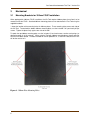
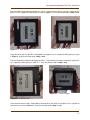
Orient the tool so that its front is facing up, the positive X axis is parallel to earth gravity as shown in Figure
6. Verify that the tool reads +1.00g +/-0.10.
Figure 6 - X Axis Positive
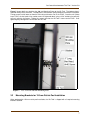
Figure 7 - X Axis Negative
Orient the tool so that its front is facing down, the negative X axis is parallel to earth gravity as shown in
Figure 7. Verify that the tool reads -1.00g +/-0.10.
10