1
2
4.3
Mounting Using a Multi-mounting Base
•
For mounting using a multi-mounting base, see the Instruction
Manual for VJCE (VJ Mounting Base).
4.4
Using Ducts
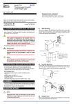
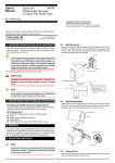
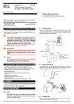
Wiring ducts should be installed at least 30 mm away from the top
or bottom of the main unit.
4.5
In case of top-and-bottom close mounting
•
For mounting, use M3 screws and crimp-on terminals with insulating sleeves appropriate for the wires used.
Tool of the crimp-on terminals to be used should be appropriate for the crimp-on terminals.
Mount a breaker on the external place.
Mount a switch or 5A circuit breaker on the place near by the
instrument, within operator’s reach. And attach the indication
that it is for disconnecting the instrument.
Transmitter should be mounted horizontally with its top and bottom slits being vertical. The top and bottom slits should not be
covered.
The area for wiring is required above and below the transmitter
(the area with slant lines).
Input signal
Example of using
Zener barrier to
When internal When external a
configure an
power is used power is used intrinsically safe
system
40 or more
PS+
+
-
-
PS+
1
-
3
-
4
+
ALM1
ALM1
ALM1
ALM2
ALM2
ALM2
(72)
COM
6
78 or more
+
3
-
1
-
4
3
4
COM
COM
Output-2 signal
3
150 or more
1
2
1
5
4
(29.5)
Analog output Alarm output
2
5
+
2
-
5
6
29.5 or more
9
8
ALM1
COM
ALM2
RS-485
communication
2 B+
5
A-
6 COM
7
Output-1 signal
ALM1
ALM1
ALM2
ALM2
ALM2
Analog output
7
40 or more
ALM1
(72)
11 10
9
+
-
Power Supply
Fig. 4.3
L+
N-
5. INSTALLATION LOCATION
•
•
For installation, avoid any location where the product may be
subject to vibrations, corrosive gases, or large amounts of
dust, or where the product is exposed to water, oil, solvents,
direct sunlight, radioactive rays, or strong electric or magnetic
fields.
If there is a possibility that lightening could induce a high
surge voltage on the power and signal lines, provide lightening arresters on the line between the field instrument and indoor instrument in order to protect the product. Install a dedicated arrester on the field side and another on the indoor side.
6. EXTERNAL WIRING
WARNING
Turn OFF the power supply and make sure that none of the
cables are not in the hot-line state before carrying out the
wiring to avoid the possibility of electric shock.
Wires are connected to the terminals of the distributor’s socket. M3
screw terminals are provided for the connection of external signals.
Attach a crimp-on lug to each wire for connection to the terminals.
• Recommended cables: A nominal cross-sectional area of 0.5
mm 2 or thicker for signal cables, and that of 1.25 mm 2 or
thicker for power cables, and shielded twisted-pair cables
(AWG24) for communication wiring cables.
All Rights Reserved. Copyright © 1999, Yokogawa M&C Corporation
GND
10
11
8
Fig. 6.1
NOTE
● Keep all sources of noise away from the power and signal cables. Otherwise, accuracy cannot be assured.
● Provide grounding to a grounding resistance of 100 ⍀.
The length of the grounding cable should be 20 m or
less. Directly connect the lead from the ground terminal
(terminal no. 8) of the distributor to the ground. Do not
carry out daisy-chained inter-ground terminal wiring.
●
Direct Current
● “Overvoltage category (Installation category)” describes
a number which defines a transient overvoltage condition. It implies the regulation for impulse withstand voltage. “II” applies to electrical equipment which is supplied from the fixed installation like distribution board.
● “Pollution degree” describes the degree to which a solid,
liquid, or gas which deteriorates dielectric strength or
surface resistivity is adhering. “2” applies to normal indoor atmosphere. Normally, only non-conductive pollution occurs. Occasionally, however, temporary conductivity caused by condensation must be expected.
● Rated fuse of 125VDC, 1A is stored. However, operators can not replace the fuse.
IM 77J01A07-01E
3rd Edition Mar.31,1997-00