1
3.2 The Rear Panel of the AS7500
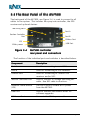
The back panel of the AS7500, see Figure 3-4, is used to connect to all
cables to the system. This includes the spray rate controller, the GPS
receiver and optional devices.
Mounting Point
Port A
Section Controller
Port
Port B
CANbus Port
IPS
USB Port
12Vdc power
Figure 3-4
AS7500 controller
rear panel
pa nel and connectors
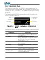
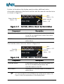
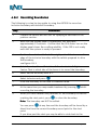
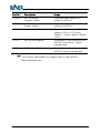
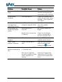
The function of the individual ports and switches is described below.
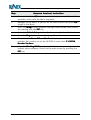
Component
Description
Port A
Used for connecting to serial SRC.
Port B
Used for connecting to GPS receivers.
CANbus Port
Used for connecting to CANbus GPS
receivers and/or SRC.
Section Controller Port
Used to connect to voltage switching SRC
cable. See SRC cable instructions.
Isolation Power Switch
(IPS)
The IPS is used to isolate all DC power
from the AS7500.
USB Port
Used to connect USB thumb-drives for
software upgrades.
DC Power Port
Connects the 12Vdc power cable.
1-1252 Ver 1.2 Rev C
AS7500 User Manual
Page 22