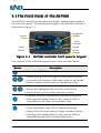
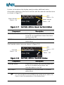
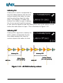
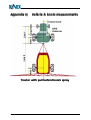
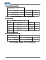
1
AS7500 User Manual Version: 1.2 Part Number 1-1252 Revision C Issue Date: May 2011 Copyright Notice All rights reserved. No part of this publication may be reproduced, stored in a retrieval system, or transmitted in any form or by any means, electronic, mechanical photocopying, recording, or otherwise, without the prior written permission of Leica Geosystems Pty Ltd. Disclaimer No liability is assumed with respect to the use of the information contained herein. While every precaution has been taken in the preparation of this publication, Leica Geosystems assumes no responsibility for errors or omissions, nor is any liability assumed for damages resulting from the use of the information contained herein. Further this publication and features described herein are subject to change without notice. Use of this system is strictly limited to providing steering assistance to the operator who must remain in control of the vehicle at all times. Leica Geosystems, including its officers servants and agents, does not make any representation to any party and will not accept any responsibility or liability whatsoever for any loss or damage of whatever nature suffered by any such person or corporation choosing or seeking to use this system or any part thereof. By use of this system you agree that Leica Geosystems is not liable or responsible for any damage whatsoever to the vehicle, any property, personal injuries, or death that may result from the use or abuse of this system. AS7500 User Manual Written for AS7500 software Version 1.3 Publication Date, May 2011 Copyright © 2011 by Leica Geosystems Pty Ltd. All rights reserved. Acknowledgements ® Windows CE is a registered trademark of Microsoft Corp. Other products and trademarks mentioned in this manual are the property of their registered owners. Leica Geosystems AG Heinrich-Wild-Strasse CH-9435 Heerbrugg Switzerland Phone: +41 71 727 31 31 www.leica-geosystems.com WARRANTY Leica Geosystems International Limited Warranty EXPRESS WARRANTY FOR HARDWARE. Leica Geosystems AG (“Leica Geosystems”), warrants to the original end user (“Customer”) that this Product will be free from defects in workmanship and materials, under normal use, for generally one (1) year, except for (i) DISTO™ products for which two (2) years shall apply, and (ii) batteries for which ninety (90) days shall apply, unless such warranty period has been extended by Leica Geosystems, and provided any and all operating and maintenance instructions are strictly respected, in particular in case of extreme and/or continuous applications/use of the Product. The warranty period begins on the proved purchase date (or if applicable, date of delivery or date of acceptance report). Leica Geosystems’ sole obligation under this express warranty shall be, at Leica Geosystems’ sole option and expense, to replace or repair the Product or part, or refund the purchase price paid for the Product. Leica Geosystems warrants any repaired or replaced Product or part for a period of ninety (90) days from shipment, or through the end of the original warranty, whichever is longer. All Products or parts that are replaced become the property of Leica Geosystems. This express warranty does neither cover consumables, such as reflectors, bulbs and fuses, nor third party products. EXPRESS WARRANTY FOR SOFTWARE. For “System Software” (defined as operating software and/or firmware necessary for switching on and running the Product), all provisions contained in this International Limited Warranty shall apply as for hardware. With respect to "Application Software” (defined as pre-installed or loadable on-board software and/or office or PC-based software for particular operations of the Product and/or data), the warranty provisions contained herein shall expressly not apply. For further information on the scope of the warranty coverage for Application Software please refer to the correspondent Software License Agreement. OBTAINING WARRANTY SERVICE. Customer must contact the authorized distributor of Leica Geosystems or, with the exception of DISTO™ products, Leica Geosystems’ Service Center indicated by Leica Geosystems within the applicable warranty period to obtain warranty service authorization. Dated proof of original purchase from Leica Geosystems or its authorized distributor and a description of the defect will be required. Leica Geosystems is not responsible for Products or parts received without a warranty service authorization. Repaired or replacement Products will be shipped to Customer at Leica Geosystems’ expense. The repaired product or part will be shipped as soon as reasonably possible. Leica Geosystems shall not be responsible for any damages occurring during such shipment. Leica Geosystems shall, at its sole discretion, decide on the place of performance for work under warranty. For Products forming part of a fixed installation, such place of performance shall be the site of such installation and Leica Geosystems shall have the right to charge for additional costs for such services under warranty if the site of the Product is other than where the Product was originally installed or shipped. WARRANTY EXCLUSIVE. Customer’s sole remedy for breach of the warranty shall be the express warranty. The foregoing warranty is exclusive and is in lieu of all other warranties, terms or conditions, express or implied, either in fact or by operation of law, statutory or otherwise, including warranties, terms or conditions of merchantability, fitness for a particular purpose, satisfactory quality and non-infringement, all of which are expressly disclaimed. Leica Geosystems shall not be liable if the alleged defect or malfunction was caused by Customer’s or any other person’s misuse, neglect, improper installation, unauthorized attempts to open, repair or modify the Product, inadequate maintenance, disregard of operating instructions, excessive load or stress, normal wear and tear, or any other cause beyond the range of its intended use, by accident, fire, or other hazards, or other cause not due or attributable to Leica Geosystems. This warranty does not cover physical damage to the Product or malfunctions resulting from the use of the Product in conjunction with any sort of ancillary or peripheral equipment and Leica Geosystems determines that there is no fault with the Product itself. WARRANTY LIMITATION OF LIABILITY. LEICA GEOSYSTEMS ALSO EXCLUDES ANY LIABILITY, WHETHER BASED IN CONTRACT OR TORT (INCLUDING NEGLIGENCE), FOR INCIDENTAL, CONSEQUENTIAL, INDIRECT, SPECIAL, OR PUNITIVE DAMAGES OF ANY KIND, OR COSTS OF PROCUREMENT OF SUBSTITUTE PRODUCTS BY CUSTOMER, OR FOR THE LOSS OF REVENUE OR PROFITS, LOSS OF BUSINESS, LOSS OF INFORMATION OR DATA, OR OTHER INFORMATION OR FINANCIAL LOSS ARISING OUT OF OR IN CONSEQUENCE WITH THE SALE, INSTALLATION, MAINTENANCE, USE, PERFORMANCE, FAILURE, OR INTERRUPTION OF THIS PRODUCT, EVEN IF LEICA GEOSYSTEMS OR ITS DISTRIBUTORS HAVE BEEN ADVISED OF THE POSSIBILITY OF SUCH DAMAGES, AND LIMITS ITS LIABILITY TO REPLACEMENT, REPAIR, OR REFUND OF THE PURCHASE PRICE PAID, AT LEICA GEOSYSTEMS’ OPTION. THIS LIMITATION OF LIABILITY FOR DAMAGES WILL NOT BE AFFECTED IF ANY REMEDY PROVIDED HEREIN SHALL FAIL OF ITS ESSENTIAL PURPOSE. DISCLAIMER. Should a court of jurisdiction not allow the entire exclusion or limitation of implied warranties or the limitation of incidental or consequential damages for certain products supplied to consumers, or the limitation of liability for personal injury, such implied warranties and such liabilities will be limited to the duration of the applicable express warranty. GOVERNING LAW AND PLACE OF JURISDICTION. This Limited Warranty shall be governed by the laws of Switzerland, excluding all conflict of laws principles and excluding the United Nations Convention on the International Sale of Goods dated 11 April 1980. The ordinary courts at the Leica Geosystems registered office in Balgach, Switzerland shall be competent. Leica Geosystems shall, at its sole discretion, also be entitled to take legal action in the competent courts at the Customer’s place of business or domicile. With this Limited Warranty, Leica Geosystems grants Customer specific legal rights which do not restrict any statutory consumer rights. Heerbrugg, July 1, 2002 TABLE of CONTENTS TABLE OF CONTENTS 1 Introduction ................................................................ ................................ ............................................... ................................ ............... 2 1.1 AS7500 Standard Features ......................................................................... 5 1.2 AS7500 Components ................................................................................... 6 1.3 Care of the Product ...................................................................................... 7 2 Installation ................................................................ ................................ ................................................. ................................ ................. 8 2.1 2.2 2.3 2.4 2.5 2.6 Installing the AS7500 ................................................................................. 10 Connecting to 12Vdc power ....................................................................... 11 Connecting the GPS .................................................................................. 12 Connecting the Spray Rate Controller ....................................................... 14 Connecting to Planters............................................................................... 15 Testing the Installation ............................................................................... 16 3 Getting Started ................................................................ ................................ ......................................... ................................ ......... 18 3.1 3.2 3.3 3.4 3.5 3.6 3.7 3.8 3.9 3.10 3.11 3.12 The Front Panel of the AS7500 ................................................................. 20 The Rear Panel of the AS7500 .................................................................. 22 Functional Modes of the AS7500 ............................................................... 23 Configuring the GPS .................................................................................. 26 Configuring the Spray Rate Controller ....................................................... 32 Configuring the Master Control Switch ...................................................... 35 Self Test the AS7500 ................................................................................. 36 Configuring the Vehicle and Boom ............................................................ 37 Measuring Vehicle & Boom offsets ............................................................ 41 Configuring the Boom Spray Parameters .................................................. 42 Measuring Latency Values......................................................................... 44 Saving & Restoring Configuration Settings ................................................ 47 4 Using the AS7500 ................................................................ ..................................................................... ................................ ..... 48 4.1 4.2 4.3 4.4 4.5 4.6 4.7 4.8 Starting a Field........................................................................................... 50 Using the AS7500 to Spray a Field ............................................................ 52 Suspending & Resuming Spraying Operations in the Field ....................... 54 Starting a New Field................................................................................... 55 Override Function ...................................................................................... 56 Forced Start (Section Control) ................................................................... 61 Backup and Restore .................................................................................. 62 Record Boundary Inclusion / Exclusion..................................................... 63 5 Safety Directions ................................................................ ................................ ...................................... ................................ ...... 70 5.1 5.2 5.3 5.4 5.5 Intended Use ............................................................................................. 72 Limits of Use .............................................................................................. 74 Responsibilities .......................................................................................... 75 Hazards of Use .......................................................................................... 76 Electromagnetic Compatibility EMC ........................................................... 80 6 The Menu System ................................................................ ................................ ..................................... ................................ ..... 82 6.1 Navigating the Menus ................................................................................ 84 TABLE of CONTENTS TABLE OF CONTENTS 6.2 6.3 6.4 6.5 6.6 6.7 6.8 6.9 6.10 6.11 6.12 The Menu Hierarchy .................................................................................. 86 The Operational Mode Menu ..................................................................... 87 Setup Mode Menus .................................................................................... 89 The General Menu ..................................................................................... 91 The Boom Menu ........................................................................................ 92 The Vehicle Menu ...................................................................................... 93 The GPS Menu .......................................................................................... 95 The Parameters Menu ............................................................................... 96 The Settings Menu ..................................................................................... 97 The System Menu ...................................................................................... 99 The Boundary Menu ................................................................................ 101 7 International Limited Warranty, Software Sof tware Licence Agreement .... 103 Appendices ................................................................ ................................ ................................................. ................................ ................. 107 Appendix A Appendix B Appendix C Appendix D Appendix E Appendix F Appendix G Appendix H Appendix I Appendix J Appendix K Appendix L Appendix M Appendix N Appendix O Appendix P Appendix Q Glossary .................................................................................... 108 AS7500 Options ........................................................................ 110 System Messages ..................................................................... 113 Troubleshooting ........................................................................ 115 Resetting the System ................................................................ 118 Upgrading Software on the System .......................................... 120 Connector Pin-Outs................................................................... 121 AS7500 Specifications .............................................................. 123 Ignition Sense Power Cable ...................................................... 124 Configuring the mojoRTK .......................................................... 125 Configuring the EZ-Guide®........................................................ 126 Configuring the EZ-Guide®.500 ................................................. 127 Configuring the Outback®.......................................................... 128 Configuring the Envizio ............................................................. 129 Configuring the Amazone Amatron+ ......................................... 130 SRC Communication parameters ............................................. 132 Vehicle & boom measurements ................................................ 134 Index ................................................................ ................................ .......................................................... ................................ .......................... 146 1 Introduction Welcome to the AS7500 User Manual. The AS7500 system is designed to connect with virtually any GPS receiver and either a Spray Rate Controller (SRC), or to the Tru Count clutches. Once installed the AS7500 provides automatic shut-off for individual boom sections on a boom spray, or planter boxes on a planter. This will greatly reduce the need for manually switching sections On or Off when going over previously worked area. The ability of the AS7500 to automatically control the state of the sections relieves the operator from a strenuous task which requires split second timing on multiple switches. Unlike other automatic section controllers, which are typically incorporated with a guidance system, the AS7500 is an autonomous system. It can be interfaced with virtually any existing SRC, or planter equipped with Tru Count clutches. Furthermore the AS7500 will connect with most GPS receivers or GPS guidance systems which can output a GPS message. Throughout this manual the use of section control, whether it be for boom spray rigs or, planters fitted with Tru Count clutches the principal operation is the same. Where necessary, details specific to planters or boom sprays will be delineated accordingly. This manual is designed to assist users of the AS7500 in the installation and operation of the AS7500. Figure 1-1 1-1252 Ver 1.2 Rev C AS7500 Controller AS7500 User Manual Page 3 This manual contains important safety directions as well as instructions for setting up the product and operating it. Refer to Section 5 for further information. Read carefully through the User Manual before you switch on the product. To ensure safety when using the system, please also observe the directions and instructions contained in the User Manual and Safety Handbook issued by the: • Agricultural machinery manufacturer. 1-1252 Ver 1.2 Rev C AS7500 User Manual Page 4 1.1 AS7500 AS7500 Standard Features The AS7500 can be used in many situations and offers the following features. Spray or plant around obstacles Automatically minimise over-application around trees or rock piles. AS7500 detects areas previously worked and shuts down sections and reactivates as necessary. Planting or Spraying headlands AS7500 detects areas previously worked as the headlands are approached and shuts down sections and reactivates as necessary Timing Delays The AS7500 can be adjusted for delays from electrical to mechanical switching. Variable Overlap Allows the operator to configure the required tolerance to over-sprays and misses. Vehicle Modelling Allows the operator to accurately define vehicle and boom dimensions for greater accuracy. Antenna Offsets Allows the operator to define the GPS antenna offsets. Compatibility The AS7500 is designed to work with both serial and CANBus GPS receivers, and with SRC requiring serial data or voltage-controlled section solenoids, or with Tru Count clutches. 1-1252 Ver 1.2 Rev C AS7500 User Manual Page 5 1.2 AS7500 AS7500 Components When the AS7500 system is first opened, please check that all of the components detailed in Table 1-1 have been supplied. Quantity Description Part Nō. N . 1 AS7500 controller 1 RAM Mount 1 DC power cable 1-2408 1 AS7500 User manual 1-1252 1 AS7500 Quick reference guide 1-1323 1 Data cable 1-2207 1 Data cable 1-2208 ® 1-0490 1-0279 Table 1-1 AS7500 Standard Sta ndard Packing List Inspect all items for visual damage. If any component appears to be damaged, contact the supplier immediately. 1-1252 Ver 1.2 Rev C AS7500 User Manual Page 6 1.3 Care of the Product Transport in a road vehicle Ensure that the product is mounted in accordance with the instructions and never carry the product loose in a road vehicle, as it can be affected by shock and vibration. Shipping If it is necessary to transport the product by rail, air or sea, always use the complete original Leica Geosystems packaging, transport container and cardboard box, or its equivalent, to protect against shock and vibration. Storage Respect the temperature limits when storing the equipment, particularly in summer if the equipment is inside a vehicle. Refer to Appendix H for information about temperature limits. Cleaning the product product and accessories Use only a clean, soft, lint-free cloth for cleaning. If necessary, moisten the cloth with water or pure alcohol. Do not use other liquids; these may attack the polymer components. Cables Cables and plugs Keep plugs clean and dry. Blow away any dirt lodged in the plugs of the connecting cables. 1-1252 Ver 1.2 Rev C AS7500 User Manual Page 7 2 Installation This section describes how to connect and install the components of the AS7500 system. A schematic of the AS7500 and how it connects to a typical SRC and GPS receiver is shown in Figure 2-1 and Figure 2-2. Figure 2-1 Schematic layout of the AS7500 with with voltage switch cable Figure 2-2 Schematic layout of the AS7500 with serial data cable 1-1252 Ver 1.2 Rev C AS7500 User Manual Page 9 2.1 Installing the AS7500 Prior to installing the AS7500 it is recommended that the operator reviews Section 3 to familiarise themselves with the individual components of the system. Step Instruction 1 Select a suitable location for the AS7500 which is convenient for the operator and does not impede upon the vision of the operator or restrict access to any vehicle controls. 2 Attach the supplied RAM mount ball to a suitable mounting point in the vehicle. A variety of RAM mount options are available from RAM suppliers which may facilitate in this mounting point. 4 Attach the RAM arm to the mounting point and then to the RAM mount on the rear of AS7500 controller. 5 Ensure that the Isolation Switch is set to the Off Position (0). Connect the DC power cable to a clean 12Vdc power source in the vehicle, then connect to the AS7500. Secure the cable using the supplied cable ties. See Section 2.2 for additional notes. 6 Connect the GPS data cable to Port B on the AS7500 and the GPS receiver output port. Secure the cable using the supplied cable ties. See Section 2.3 for additional notes. 7 Connect the SRC cable as per the instructions supplied with the SRC cable. Then connect the cable to the Section Controller Port on the AS7500. Secure the cable using the supplied cable ties. See Section 2.4 for additional notes. 8 Slide the Isolation Switch is set to the On Position (1). 9 The AS7500 has been installed and is now ready to be calibrated for use. See section 2.5 to confirm the system has been correctly installed in the vehicle. 1-1252 Ver 1.2 Rev C AS7500 User Manual Page 10 2.2 Connecting to 12Vdc power The AS7500 is designed to operate from a clean 12Vdc power source. The use of a cigarette lighter socket is not recommended as the plug may become loose and cause intermittent power to the AS7500. The AS7500 is fitted with an internal self-resetting fuse, hence it is not necessary to fit an in-line fuse to the power cable. However if the cable is connected directly to the vehicle’s batteries it is recommended that a fuse be fitted accordingly. The AS7500 is fitted with an Isolation Power Switch (IPS) on the rear panel, this switch completely removes power from the AS7500 controller. The IPS should be set to the Off Position (0) if the vehicle will not be used for several months to prevent any power drain from the vehicle. The standard 12Vdc power cable (P/n 1-2408) supplied with AS7500 is designed for a maximum of 8A operation. An optional power cable may be purchased for a maximum of 16A operation, see Appendix B for details. The AS7500 may be configured to start automatically after the vehicle has started by sensing the vehicle’s ignition. An optional power cable, with the ignition sense, may be purchased for this feature, see Appendix I for details. DC Power Cautionary Notes The power cable should be carefully routed so as not to rub or wear through which may lead to a short circuit on the vehicle. 1-1252 Ver 1.2 Rev C AS7500 User Manual Page 11 2.3 Connecting the GPS A GPS receiver / guidance system must be connected to the AS7500 for the system to function. The GPS data cable is normally connected to Port B on the rear of the AS7500. The AS7500 kit is supplied with two different data cables (P/n1-2207 & 1-2208). Typically one of these cables will suit most GPS receivers. See Appendix B for optional cables and peripherals to suit the AS7500 for non-standard GPS receivers. The AS7500 is also capable of connection to GPS receivers with a CANbus interface, using the CAN port on the rear of the AS7500. The set up details for these receivers are supplied with the appropriate cable. Nongenuine data cables should not be used as these may damage the AS7500 or GPS receiver. In order for the AS7500 to function correctly, the GPS receiver must be configured to receive the NMEA data message $GPGGA. For optimal use, the GPS receiver should be configured with the following parameters; NMEA message Update rate Baud rate GGA, VTG 5Hz 19,200 baud Consult the GPS receiver / guidance system user manual for details on configuring the output data if required. If the AS7500 is connected to a spray rate controller with a serial interface at baud rate 9600 (see Appendix N) then the GPS baud rate must also be set to 960 baud. The AS7500 will operate with a slower Update rate (1Hz), however the functionality of the AS7500 will be compromised. The VTG NMEA string is optional and not essential for the AS7500 to function correctly. 1-1252 Ver 1.2 Rev C AS7500 User Manual Page 12 GPS Accuracy The relative accuracy of the GPS system will determine the overall performance of the AS7500 system. The more accurate the GPS, the more accurate boom section shut off will be with the AS7500. Many GPS receivers quote their accuracy as “pass to pass”, which relates to a short time period, typically ten minutes or so. However when spraying a field this may take several hours, hence it is important to consider this accuracy statement. RINEX recommend that the AS7500 always be used with a DGPS to provide optimal accuracy with the overall system. It is the operator’s responsibility to determine the accuracy of the GPS. See Section 3.4 for further details. 1-1252 Ver 1.2 Rev C AS7500 User Manual Page 13 2.4 Connecting the Spray Spray Rate Controller The AS7500 is compatible with numerous Spray Rate Controllers (SRC), these typically have unique cables for the respective installation. At the time of ordering the AS7500 kit the SRC cable should have been ordered. Each SRC cable is supplied with relevant installation instructions. See Appendix B for a list of SRC cables. The AS7500 is compatible with both, voltage switching SRC installations, and serial data installations. Accordingly, the connection for the AS7500 controller will be determined by the SRC cable. The SRC may connect to either the Section Controller Port, Port A, or the CANBus port on the rear of the AS7500 controller. In addition to connecting the SRC cable it may also be necessary to connect to the SRC Master switch. If necessary, instructions will be supplied with the SRC cable. See Section 3.5 for further details. Mapping the SRC sections The AS7500 will output the status of the boom sections, that is whether they are On or Off, so that third party guidance and/or mapping devices can accurately map the field where it has been sprayed. To enable other mapping devices to display the current state of the sections, the AS7500 outputs the boom section status, On or Off, using the data format string for a RAVEN 460 controller. This data string is output on Port A at 9600 baud rate whenever the Controller is set to Voltage. The GPS Port will also be set to 9600 baud and it will be necessary to set the GPS receiver also to 9600 baud rate. 1-1252 Ver 1.2 Rev C AS7500 User Manual Page 14 2.5 Connecting to Planters Planters The AS7500 is compatible with a number of planters including John Deere, Kinze, Case and White which are fitted with Tru Count clutches. The Tru Count logo is shown in for easy identification of their product. Figure 2-3 Tru Count for Planters The AS7500 connects to the Tru Count clutches the same as a voltage section controller via the Section Controller Port on the rear. Tru Count will supply the necessary cables to connect the AS7500 to their clutches. One major difference between the Tru Count clutches and a conventional SRC is that the voltage is supplied through the Section Controller Port in reverse logic. Hence when the voltage is On for a SRC it is Off for the Tru Count clutches. This is handled by the AS7500 and does not require any intervention by the operator. The operator is required to select the Tru Count clutches in the Setup mode menu 6.1 SETTINGS-Controller Type < Tru Count>. The setup of planter rows to match the sections automatically controlled by the AS7500 is at the operator’s discretion. The maximum number of sections that can be controlled is 13. Hence in a 36 row planter it may be set with 3 boxes per section which would use only 12 sections and provide optimal control. Tru Count Valve Box – Upgrade The Tru Count valve boxes must be upgraded to work with the AS7500. If the upgrade kit is not fitted, the AS7500 may fail to operate correctly when powering clutches. 1-1252 Ver 1.2 Rev C AS7500 User Manual Page 15 2.6 Testing the Installation Prior to commencing operations with the AS7500 the system should be checked for operational status as per the following instructions. If the system does not perform as per the instructions, the local dealer should be consulted for assistance. Step Instruction 1 Confirm that the 12Vdc power cable, GPS data cable and SRC are all connected as per the installation notes and to the correct ports on the AS7500. 2 On the rear panel of the AS7500, slide the IPS to the On position(1),if not already done so. 3 Press the power button on the front of the AS7500 unit. There will be a delay of approximately 15 seconds while the AS7500 powers up. 4 The display panel will be activated, showing the Operational menu information. This confirms that the AS7500 has been correctly installed and powered. 5 Press the Power button on the front panel to turn Off the AS7500. 1-1252 Ver 1.2 Rev C AS7500 User Manual Page 16 This page is intentionally left blank 1-1252 Ver 1.2 Rev C AS7500 User Manual Page 17 3 Getting Started This section details the steps taken for the first time user of the overall system. In particular this section describes the components of the AS7500 and their respective functions. It is important that the components and connectors of the AS7500 are correctly identified to gain the maximum benefit from the system. The terminology used with the AS7500 and the connected devices including the GPS receiver and spray rate controller is equally important. Furthermore this section describes the necessary information which includes measurements of the vehicle to ensure that the system will operate correctly. 1-1252 Ver 1.2 Rev C AS7500 User Manual Page 19 3.1 The Front Panel of the AS7500 The AS7500 controller incorporates the display, speaker and keypad on the front face panel. The display and keypad of the AS7500 controller is illustrated in Figure 3-1. Navigation Buttons Display Panel Enter Button Power ON/OFF Escape Button Speaker Figure 3-1 AS7500 controller front panel panel & keypad The function of the individual keypad buttons are described below. Button Description • Turns the AS7500 On and Off. • Moves Up and Down through the setup menu sections. • Increases and decreases field values when in edit mode. • Selects display options when in Operational mode. • Moves to individual setup menu options within a section. • Moves the highlighted edit position in edit mode. • Selects boom sections when override is active. • Switches between operational mode and setup menu. • Pressing and holding down for two seconds while in Operational mode clears all treatment data. • • • • Enters and exits edit mode in the setup menus. Turns the master switch On in Operational mode. Selects all/none boom sections when override is active. Pressing and holding down for two seconds while in Operational mode opens the Boundary menu. 1-1252 Ver 1.2 Rev C AS7500 User Manual Page 20 3.1.1 The Display Panel The AS7500 display panel can be set for maximum brightness and contrast, which allows for optimal viewing, as either a positive or negative image. The display is shown as either a positive image, black text on white background as shown in Figure 3-2. Alternatively the AS7500 can be configured as negative image, white text on a black background as shown in Figure 3-3. Figure 3-2 AS7500 positive image display Figure 3-3 AS7500 negative image display The setting for screen is configured in the Setup Mode at 1.2 GENERAL <Brightness>. Throughout this manual, the display panel is only shown as white text on a black background, a negative image. 1-1252 Ver 1.2 Rev C AS7500 User Manual Page 21 3.2 The Rear Panel of the AS7500 The back panel of the AS7500, see Figure 3-4, is used to connect to all cables to the system. This includes the spray rate controller, the GPS receiver and optional devices. Mounting Point Port A Section Controller Port Port B CANbus Port IPS USB Port 12Vdc power Figure 3-4 AS7500 controller rear panel pa nel and connectors The function of the individual ports and switches is described below. Component Description Port A Used for connecting to serial SRC. Port B Used for connecting to GPS receivers. CANbus Port Used for connecting to CANbus GPS receivers and/or SRC. Section Controller Port Used to connect to voltage switching SRC cable. See SRC cable instructions. Isolation Power Switch (IPS) The IPS is used to isolate all DC power from the AS7500. USB Port Used to connect USB thumb-drives for software upgrades. DC Power Port Connects the 12Vdc power cable. 1-1252 Ver 1.2 Rev C AS7500 User Manual Page 22 3.3 Functional Modes of the AS7500 The AS7500 has two functional modes, Setup and Operational mode. Information shown in the display panel will be different depending upon the functional mode the AS7500. The key toggles the AS7500 between Operational and Setup mode. The functional mode is easily distinguished on the display panel. 3.3.1 Setup Mode The Setup mode allows the user to configure the AS7500 as required. The Setup menu is indexed to allow the user to easily step through the menu as required. See Section 6 for further detail on the menu system. The display panel of AS7500 in Setup mode will be similar to the picture as shown in Figure 3-5. Menu name Setup icon Menu item Item Value Figure 3-5 AS7500 display panel in Setup Mode The individual areas of the Setup mode display are described below. Component Description Menu name Displays the Menu item number followed by the Menu name. Menu Item Displays the selected item within a menu Item value The value of the selected menu item. Setup Icon Icon showing that the AS7500 is in Setup Mode. The AS7500 does not record any spraying when in Setup Mode. 1-1252 Ver 1.2 Rev C AS7500 User Manual Page 23 3.3.2 Operational Mode The Operational mode allows the AS7500 to automatically control the boom sections when spraying a field. The Operational mode provides the operator with status information of the AS7500 controller as it is working in the field. The display panel of AS7500 in Operational mode will be similar to the picture as shown in Figure 3-6. Boom MCS Status On / Off Overrides GPS Status Text display Figure 3-6 AS7500 display panel in Operational Operational Mode The individual areas of the Operational mode display are described below. Component Description Boom A representation of the configured boom, showing sections. MCS Status Shows whether the MCS is active or inactive. If the Boom is a solid white block the MCS is On, if the box is hollow (as shown) the MCS is Off. Overrides Shows which sections have been selected to be overridden. Text Display The selected text information is displayed in this area. On / Off A bar representing whether the boom section is deemed to be ON or OFF. GPS Status Icon Displays the status of the GPS data currently being received. 1-1252 Ver 1.2 Rev C AS7500 User Manual Page 24 Further to the above the display panel provides additional status information relating to the boom sections and the manual override status as shown in Figure 3-7. MCS Status - On Boom Section Status - On Figure 3-7 Boom Section Status - Off AS7500, MCS & Boom Boom Section Status Component Comp onent Description Boom Section Status A triangular icon shows the boom section to be On or a small block shows the boom section to be Off. MCS Status The MCS is On as the status is a solid white block. The Override status icons are shown in Figure 3-8. MCS Status - Off Override Status - On Figure 3-8 Component Override Status - Off AS7500, MCS & Override Status Description Override Status A solid block shows the override status to be On or a hollow block shows the override status to be Off. MCS Status The MCS is Off as the status is a hollow white block. It is not possible for the AS7500 to be configured as above, the Figure is only for explanation of the display panel. 1-1252 Ver 1.2 Rev C AS7500 User Manual Page 25 3.4 Configuring the GPS The AS7500 will operate with almost any GPS receiver or guidance system which can output a NMEA or NMEA 2000 message. The AS7500 does not require a GPS mapping screen to operate. In order for the AS7500 to correctly function the GPS requirements are as follows. NMEA message GGA (VTG optional) Update rate 5Hz Baud rate 19,200 baud (optional settings) Connect the GPS receiver / guidance system to the correct port on the back panel of the AS7500 as described in Section 2.3. The AS7500 is supplied with data interface cables to suit most popular GPS systems, however it may be necessary to order an additional cable to suit individual systems. See Appendix B for optional cables that are available for the AS7500. Instructions for configuring popular GPS receivers / guidance systems including the Leica mojoRTK, Trimble EZ-Guide ® Plus, EZ-Guide ® 500 and Outback® GPS Guidance are provided in Appendix J through to Appendix N. For all other GPS receivers / guidance systems refer to the GPS manufacturer’s manual. Configuring the GPS Type The AS7500 allows the use of GPS receivers providing NMEA or NMEA2000 format messages, using RS232 or CANbus interfaces. In order to set up the AS7500 to receive the GPS data on the correct port, navigate to the GPS Type option, see Section 6.10 to change the GPS receiver type. For all non-CANbus GPS receivers using the NMEA messages, connect to Port B on the AS7500. For CANbus GPS receivers use the NMEA2000 messages, connect to the CANbus Port on the AS7500. 1-1252 Ver 1.2 Rev C AS7500 User Manual Page 26 Configuring the GPS Baud Rate If necessary the AS7500 can be configured with optional GPS baud rates. This would be done if the GPS receiver cannot be configured to 19,200 baud to match the AS7500. The GPS Baud Rate has no effect if the NMEA2000 message is used. It is essential that the baud rate being transmitted from the GPS and that being received by the AS7500 is exactly the same. Failure to match the baud rates will prevent the AS7500 from correctly receiving the GPS data. In order to setup the AS7500 to function at a different baud rate navigate to the Baud Rate option, see Section 6.8 to change the baud rate. The Baud Rate should not be set below 19200bps unless absolute necessary. A slower Baud Rate may affect the performance of the AS7500. If the AS7500 is connected to a SRC that uses 9600 Baud Rate, see Appendix N, it will be necessary to configure to the GPS also to 9600 Baud Rate. Configuring the DGPS Requirements The AS7500 can operate with either non-corrected GPS signals or differentially corrected GPS signals (DGPS). It is important to note the use of non-corrected GPS signals is not recommended as this will have a direct impact upon the accuracy of the overall system. There are several common forms of DGPS correction services which include WAAS, EGNOS, Beacon (Coast Guard), OmniSTAR®, and StarFire®. All of these services provide a more accurate GPS position (DGPS) and are recommended for use with the AS7500. Furthermore RTK signals may also be used with the AS7500 for accurate GPS. It is the user’s responsibility to determine the GPS accuracy for use with the AS7500. 1-1252 Ver 1.2 Rev C AS7500 User Manual Page 27 It is however possible to configure the AS7500 to operate on GPS data only. In order to setup the AS7500 to function in this manner navigate to the Diff Required page, see Section 6.8 in the GPS menu, and toggle the setting from Yes to No. The AS7500 will now function with either DGPS or GPS only data. If the Diff Required menu is set to No, the AS7500 will operate with either DGPS or GPS signals. The GPS health message, as shown in Table 3-1 describes whether the received GPS message is differentially corrected. Configuring the Velocity Velocity Filter If the AS7500 is operated with non-corrected GPS signals the heading of the spray rig may be erratic which may cause irregular behaviour of boom sections shutting On and Off, particularly on the outside sections. To minimize this effect the VTG (heading) message may be disabled at the GPS receiver / guidance system and the AS7500 can smooth the vehicle’s heading using a Velocity Filter. The filter may be increased in magnitude to further dampen the erratic behaviour of the non-corrected GPS signals. RINEX recommend that the AS7500 always be used with a DGPS to provide optimal accuracy with the overall system. It is the operator’s responsibility to determine the accuracy of the GPS. Velocity Filter has no effect when the $VTG string is being received. GPS Alarms The AS7500, when in the OPERATIONAL mode, with the MCS in the On state, will provide an audible alarm in the following situations. • DGPS Required Yes Whenever GPS Health reports other than “Good GPS” 1-1252 Ver 1.2 Rev C AS7500 User Manual Page 28 • DGPS Required No Whenever GPS Health reports other than “Good GPS”, except for “No DGPS” The cause of the alarm should be investigated, and rectified, before continuing to use the AS7500. The Sound option in Section 6.5 General Menu must be set to Yes for the alarm to be active. Configuring the GPS Antenna Offsets When using GPS the actual position is computed at the GPS antenna. However this is not the physical location where the sections are located such as the boom spray or the planter boxes. Hence it is necessary to measure the distances or offsets, from the GPS antenna to the physical section. Most GPS antennae are located along the centreline of the vehicle and or spray rig. However if for some reason the antenna is offset from the centreline then it will be necessary to enter a Cross Track value. When standing at the rear of the vehicle looking forward, if the antenna is located on the left hand side of the vehicle the offset is entered as a negative value, if the antenna is located on the right hand side of the vehicle the offset is entered as a positive value. The distance between the GPS antenna and the boom sections is not measured directly between the points. The AS7500 provides accurately modelling of the boom by measuring points along the length of the spray rig to compute the orientation of the boom relative to the vehicle. See Section 3.9 for the necessary measurements. GPS Status 1-1252 Ver 1.2 Rev C AS7500 User Manual Page 29 The number of satellites used by the GPS receiver / guidance system is reported in the GPS status message on the display panel. It is necessary to have four or more satellites for a valid GPS position. GPS Health Further to the GPS Status, the GPS Health is a summary of several parameters related to the GPS data. The meaning of GPS Health values are given in the following table. Message Description Good GPS Good DGPS data is being received (GGA message only). Good GPS (V) Good DGPS data is being received (GGA & VTG messages). No DGPS Good GPS data is being received but no differential correction signal is received. Poor GPS Poor DGPS data is received, less than four satellites or a PDOP greater than 10. The AS7500 will not function. No Pos Correct data type & baud rate, no GPS position given in the data. No NMEA Invalid data being received. No Data There is no data being received through the GPS port. Table 3-1 1-1252 Ver 1.2 Rev C GPS Health Messages AS7500 User Manual Page 30 3.4.1 Testing the GPS G PS connection to the AS7500 Once the AS7500 has been correctly configured for the GPS, it should be tested for correct operation as described in the following steps. Step Instruction Screen Screen 1 Start the AS7500 using the On/Off button. 2 The AS7500 will start into the Operational mode after about 15 seconds and the display panel will appear as shown until a valid GPS signal is received. 3 Once the AS7500 is receiving valid DGPS information on the correct port, the display will show a moving satellite symbol as shown. 4 Scroll to the GPS health messages using the or buttons. If no GPS data is being received the display will be as shown. 5 Once GPS data is received the message will be changed to show the status of the GPS data being received. See Table 3-1 for a description of the GPS health messages. If the test procedure fails, confirm that the GPS receiver / guidance system is correctly configured and that the data cable is connected to the correct Port on the AS7500 controller. 1-1252 Ver 1.2 Rev C AS7500 User Manual Page 31 3.5 Configuring the Spray Rate Controller The AS7500 can be connected to a wide range of SRC. The type of SRC will determine to which port the SRC cable is connected. Individual SRC cable kits are supplied with installation instructions. The AS7500 will control automatic boom section switching via one of two methods for individual SRC. Voltage switching cables are connected to the Section Controller port on the rear of the AS7500. Data interface cables are connected to either Port A or the CANBus port on the rear of the AS7500. Selecting the SRC The AS7500 can be configured to work with different types of spray rate controllers. Navigate to the Controller Type option, see Section 6.10 to select the required Controller from the list. 3.5.1 Configuring the AS7500 for voltage switch installations There are no additional steps required to set up the AS7500 for voltage switch installations. The SRC cable will be connected to the Controller port on the rear of the AS7500. The next step is to check the Master Control Switch, see Section 3.6 for further details. In some rare cases the order of the boom section switches may need to be changed to allow for fence nozzle switches that appear as boom section switches. See Section 6.6 for further details. 3.5.2 Configuring the AS7500 for data interface installations SRC data interface cables can be connected to either Port A, for RS232 interfaces, or the CANbus port. Consult the SRC documentation and connect the supplied cable to the correct port for the SRC interface. 1-1252 Ver 1.2 Rev C AS7500 User Manual Page 32 Selection of the Controller Type in the option above will automatically configure communication parameters for the AS7500. Appendix N lists common SRC and their respective communication parameters. SRC communication alarm If the communication between the AS7500 and the SRC is broken, the AS7500 will show a warning on the display panel and trigger an audible alarm for approximately two seconds. AS7500 alarm message when communication to the SRC is broken. This feature is not available for controllers connected to the Section Controller port. 3.5.3 Testing the SRC connection to the AS7500 To test Spray Rate Controller cable, follow the steps below. Step Instruction Screen 1 Start the AS7500 using the On/Off button. 2 The AS7500 will start into the Operational mode after about 15 seconds and the display panel will appear as shown. 3 Switch the SRC Master switch ON. If the vehicle is stationary the display will not change. 1-1252 Ver 1.2 Rev C AS7500 User Manual Page 33 Step Instruction Screen 4 If the vehicle is moving, with GPS connected. The MCS status will be On, and the Section status will be On as shown, assuming three boom sections. 5 If number of boom sections is more than 13, the displayed will be as shown. 5 Switch the SRC Master switch OFF. A delay may occur between the switching of the Master Section switch and when the Master Status is displayed on the AS7500. This delay is due to the type of electrical circuit switching used within the SRC. If the display panel status value does not change, check that the cable has been installed correctly. 1-1252 Ver 1.2 Rev C AS7500 User Manual Page 34 3.6 Configuring the Master Control Switch The Master Control Switch (MCS) is the switch (source) which is used to control both the AS7500 controller and the SRC. The vast majority of SRC have a master switch which is used to switch all sections On and Off as required. Ideally this will be setup as the MCS. The SRC Cable kit will indicate if the SRC master switch can be set as the MCS. However in some cases it is not possible, or practical to use this as the MCS. In these cases the front keypad of the AS7500 may be used as the MCS. Prior to use of the AS7500 it is necessary to setup the MCS. Navigate to the MCS setting, Master Source option. See Section 6.10 to select the required option from the list. The MCS (Master Source) may be configured from the following settings. Control Setting Keypad Device Used The button on the front panel of the AS7500 controller (default setting). External Typically this will be the Master switch on the SRC. The AS7500 requires a constant 12Vdc signal on pin 11 of the Section Controller Port. Bipole Typically this will also be the Master switch on the SRC. It is observes a 12Vdc pulse on one wire (pole) to open the valve and then a 12Vdc pulse on the opposite wire (pole) of the valve to close it. The AS7500 requires 12vDC pulse on pins 11 and 16 of the Section Controller Port. With Bipole selected as the MCS, only 12 boom sections can be used on the Section Controller port. Bipole must be set as the MCS before the cable is connected to the Section Controller port. Damage may occur to either the AS7500 the SRC, or both units. 1-1252 Ver 1.2 Rev C AS7500 User Manual Page 35 3.7 Self Test the AS7500 Prior to using the AS7500 for the first time, the AS7500 Self Test should be completed to ensure that all components are correctly installed and operational. The Self Test is used to check that the AS7500 is communicating correctly with the SRC. It starts with a sound test and then turns each section On for three seconds. To start the test, set the Self Test option to “Yes”. The left most boom section (when looking from behind the boom in a forward direction) will come on first. When the section test is finished it tests the MCS for general switching On and Off. To If the MCS is set to External, it should be turned On prior to starting the Self Test. 1-1252 Ver 1.2 Rev C AS7500 User Manual Page 36 3.8 Configuring the Vehicle and Boom When setting up the AS7500 for the first time or for use in a new vehicle, there are various settings that must be configured for AS7500 to function correctly and accurately. The AS7500 models the movement of the entire spray rig, whether it is a self propelled boom spray or a pull behind (trailer) boom spray. This allows the true position of the spray boom and its orientation to be accurately computed for precise control when switching the boom sections On and Off. The measurements as described in the following sections and depicted in Figure 3-10 through to Error! Reference source not found. are to be accurately measured for the relevant spray rig and recorded in the tables provided for future reference. GPS Offset (Cross track) The distance between the centreline of the vehicle and the GPS antenna must be entered as the Cross track value. Measure the distance and enter a positive value if the antenna is to the right of the centreline of the vehicle as viewed from the rear of the tractor facing forwards. Enter a negative value if the antenna is to the left of the centreline of the vehicle as viewed from the rear of the tractor facing forwards. The Cross track value can be edited in the GPS Menu. GPS Offset (Long track) track) The Long track is the distance from the GPS antenna to the centreline of the front axle on the spray vehicle. If the GPS antenna is located forward of the front axle, the distance is entered as a negative value. If the spray vehicle is equipped with a front mounted boom, the Long track measurement is to the flow point of the boom and not the front axle. 1-1252 Ver 1.2 Rev C AS7500 User Manual Page 37 Boom Settings The Boom Settings determine the overall width of the spray boom being used. Enter the number of boom sections and the width of each section in the Boom Width Menu. Front Boom The Front Boom option is used when the physical boom is located at the front of the vehicle. The location of boom will be modelled correctly when this option is selected as Yes. See Appendix Q for a sample configuration. Mid Offset The Mid Offset option is used when the physical boom is split along the longitudinal axis of the vehicle. Typically this will be on a self propelled sprayer with mid mounted boom and the central part of the boom at the rear of the vehicle. The mid offset for the boom is for one central section of the boom only and must be one complete section for the boom section switches, see Appendix Q for a sample configuration. 1-1252 Ver 1.2 Rev C AS7500 User Manual Page 38 Boom Section Section Translation The Translation option is used when the boom sections do not map “oneto-one” to the outputs of the Section Controller port. Using this option, the AS7500 outputs can be mapped to different boom sections. To use translation, edit the character in each boom section position and change it to the position that it is to be mapped to. As an example if a five section boom had two additional switches placed for further control of the two outer most sections as shown in Figure 3-9 then it would be necessary to translate which sections would be activated by the AS7500. In this example it would be necessary to have the translation as shown in the sequence beneath the boom in Figure 3-9. Figure 3-9 Boom Section Translation There can be no duplication of section values in the translation table. In the example given it would be necessary to reconfigure the AS7500 to seven sections. 1-1252 Ver 1.2 Rev C AS7500 User Manual Page 39 Link and Axle Distances The Link and Axle distances are used when determining the path of the spray rig as it moves around the field. First, enter the number of links for the spray rig. Then enter the distances for each link. The Link and Axle distances should be measured as follows: Link Setting Measurement Link 1 Link 1 is measured from the front axle centreline to the vehicle hitch point. Axle 1 Axle 1 is measured from the rear axle of Link 1 to the hitch point of Link 1. Link 2 Link 2 is measured from the hitch point of Link 1 to the hitch point or the flow point if it is the last link. Axle 2 Axle 2 is measured from the rear axle of Link 2 to the pivot point of Link 2. Link 3 Link 3 is measured from the hitch point of Link 2 to the flow point. Axle 3 Axle 3 is measured from the rear axle of Link 3 to the flow point. See Figure 3-10 for an illustration of the Link settings. The number of Links and the Link and axle distances can be edited in the Vehicle Menu. 1-1252 Ver 1.2 Rev C AS7500 User Manual Page 40 3.9 Measuring Vehicle Vehicle & Boom offsets For precise control of the AS7500 it is necessary that all measurements are accurately recorded and entered into the system. Some of the measurements required will be unique to the vehicle configuration, a selfpropelled sprayer or tow behind, and the various equipment diagrams indicate the measurements required. The typical measurements required, for a tractor and trailer configuration is shown in Figure 3-10. A more comprehensive list of spray vehicles and a table to record their respective measurements is provided in Appendix Q. Tractor with pull behind boom spray Figure 3-10 Tractor with pull behind boom spray 1-1252 Ver 1.2 Rev C AS7500 User Manual Page 41 3.10 Configuring the Boom Spray Parameters The following parameters are used when determining when to turn the boom sections On or Off. To optimize the usage of AS7500 it is important that these settings are configured correctly. Tolerance The Tolerance or Overlap is used to decide when to turn boom sections On or Off. When set to its default of 1%, the system will turn the sections On whenever any part of the sensed area has not been sprayed. It is effectively the percent of miss that the system will tolerate. If the value is increased, the system will not turn the sections On when traversing over a small missed area such as a line between two spray swaths. The Tolerance value can be edited in the Parameters Menu. Min Delay This value defines the minimum amount of time that should elapse before a section that has been switched Off can be again turned On, and vice-versa. The feature is designed to prevent problems due to fast switching of solenoid valves. The entered value is a percentage of the sum of the Latency On and Latency Off values. The Min. Delay value can be edited in the Parameters Menu. NOTE: This is an advanced tuning parameter and should only be changed from its default value under instruction from authorised support personnel. 1-1252 Ver 1.2 Rev C AS7500 User Manual Page 42 Latency On Latency On is used to compensate for any time delay between the time the system requests the valves to open and the actual time that this takes place. For example, if it takes one second for a valve to open, a Latency On of one second should be entered. In this case the signal to open the valve will be sent to the valve a second before the valve needs to open. This is illustrated in Figure 3-11. Latency Off Latency Off is opposite to Latency On and is used to compensate for any time delay between the time the system requests the valves to close. Latency On MCS On Valves Open jetsjets-spraying Latency Laten cy Off MCS Off Valves Closed jetsjets-not spraying Figure 3-11 AS7500 Latency values 1-1252 Ver 1.2 Rev C AS7500 User Manual Page 43 3.11 Measuring Latency Values The following parameters are used when determining when to turn the boom sections On or Off. To optimize the usage of AS7500 it is important that these settings are configured correctly. The quickest way to estimate the latency of the sprayer is to use a stop watch, turn a spray section On and time the delay between this action and when spray is coming out the nozzle onto the crop. The same steps would be taken to measure the latency value when switching a section Off. These observations require precise timing and would need to be repeated many times to confirm that the times were accurate. The times would need to be measured to less than 0.01 of a second for precise control. A more accurate and convenient way to measure latency is with the following procedure. Step Instruction Diagram 1 Drive slowly in a straight line down the field for 200m with the sprayer on. The tank should have water only for the purpose of this exercise. Have another person mark the left end nozzle of the boom with two pegs and a rope half way along the spray run. 2 At right angles to the previous spray run, spray at a constant speed of 20km/h across the spray mark with one end of the boom crossing over the rope. Ensure that you have allowed enough distance before crossing over the line for the boom trailer to straighten up behind the tractor. Have someone measure the distance from the rope to where the sprayer actually turned on the sections. 1-1252 Ver 1.2 Rev C AS7500 User Manual Page 44 Step Instruction 3 Diagram Calculations - Metric If Speed(km/h) = The speed of the vehicle in kilometres per hour Distance (m) = The distance from the rope to where the sprayer turned on the sections in metres. Calculate the Latency On using this formula: Latency On(s) On(s) = Distance(m) ÷ Speed(km/h) x 3.6 For example Assuming the operator was travelling at 20km/hr and the distance from the rope to where the sprayer turned on the sections is 5 metres: Latency(s) = 5(m) ÷ 20(km/h) x 3.6 = 0.9 seconds. Calculations - Imperial If Speed(mph) = The speed of the vehicle in miles per hour Distance (in) = The distance from the rope to where the sprayer turned on the sections in inches. Calculate the Latency On using this formula: Latency On(s) = Distance(in) ÷ Speed(mph) x 0.056 For example Assuming the operator was travelling at 10mph and the distance from the rope to where the sprayer turned on the sections is 150 inches: Latency(s) = 150(in) ÷ 10(mph) x 0.056 = 0.8 seconds. 4 Repeat steps 1 to 3, altering the Latency On figure by plus or minus 0.1 seconds, until the optimum result is achieved. To calculate the Latency Off value the same procedure is followed, except that the measurements are observed where the sections are switched Off crossing into the sprayed area. 1-1252 Ver 1.2 Rev C AS7500 User Manual Page 45 The following examples show possible scenarios and how to resolve the latency settings for optimum control of the AS7500. Both Latencies set too low Both Latencies set too high Latency ON is normal Latency ON set too high Latency OFF set too low Latency OFF is normal Optimum Latency setup Abnormal situation Check link and axle measurements, reset latency values to 0.0s and repeat test 1-1252 Ver 1.2 Rev C AS7500 User Manual Page 46 3.12 Saving & Restoring Configuration Settings All the settings for the unit configured for a particular vehicle can be backed up and restored to a USB-stick (USB thumb drive) if required. Hence when moving the device to a different vehicle or installation, a restore from a USB-stick is all that is required to get started. This makes changing the unit between vehicles simpler. To save the system settings 1. Place a blank USB-stick in the USB Port prior to turning on the AS7500. 2. Go to menu 7.3 Upgrade Software menu and toggle the No option to Backup. 3. The system will display “Complete” when the backup is successful. To restore the system settings setting s 1. Place the USB-stick, which contains the Backup settings for the rig which is to be configured, into the USB-Port prior to turning on the AS7500. 2. Go to menu 7.3 Upgrade Software menu and toggle the No option to Restore. 3. The system will say “Complete” when the restore is successful. 1-1252 Ver 1.2 Rev C AS7500 User Manual Page 47 4 Using the AS7500 Once the AS7500 has been setup and calibrated it is a very simple system to use and requires only one button to start and stop operations in the field. This section provides the user with a step by step guide to using the AS7500 on a daily basis in the field. Should it be necessary to suspend or pause operations in the field, this section also describes the necessary steps. While the AS7500 does not require user intervention during normal operation, the method of overriding the AS7500 is also described in this section. 1-1252 Ver 1.2 Rev C AS7500 User Manual Page 49 4.1 Starting a Field Prior to starting in a new field it is essential that the AS7500 has been setup and all relevant dimensions of the spray rig have been measured and recorded as shown in Section 3.9. It is also necessary that the system has been calibrated in accordance with Section 3.11. Once these steps have been completed then the system is ready for use to start work in a field. Prior to starting any field it is recommended that the system be cleared of all previous information. The first step is to start the vehicle and any necessary pumps or ancillary equipment in preparation for the field activities. The next step is to power up the AS7500 and the SRC installed in the vehicle. The field data can then be cleared using one of two methods. 4.1.1 Clearing a Field from Operational Mode This Method is the quickest method to clearing all treatment data from the AS7500 in preparation to commence a new field. While in Operational mode, hold down the button on the display panel for a few seconds until the screen displays “Clearing…”. The message “Treatment Clear” will be displayed when the field has been successfully cleared. Any boundaries that exist will also be cleared. These steps are shown in Figure 4-1. Figure 4-1 Clearing Treatment data All previous treatment data will be lost when the field is cleared. 1-1252 Ver 1.2 Rev C AS7500 User Manual Page 50 4.1.2 Clearing a Field from Setup Mode The field can be reset in the Setup Mode by navigating to the menu 1.1 GENERAL-Field Reset and then toggling the option to Yes. This will clear all treatment data from the AS7500 in preparation to commence a new field. From the Operational Mode, with the MCS Off, press the button to enter Setup Mode. The Setup menu 1.1 GENERAL-Field Reset is the first menu when entering the Setup Mode. Press the mode, and press the or button to enter EDIT buttons to change the NO to a YES. Press the button to exit EDIT mode. The field will be cleared, as shown in Figure 4-1. 1-1252 Ver 1.2 Rev C AS7500 User Manual Page 51 4.2 Using the AS7500 to Spray a Field The following is a step by step guide to using the AS7500 to spraying or a field with the AS7500 using automatic boom section control. Step Instruction 1 If not already done so, start the vehicle and any necessary pumps or motors to operate the boom spray. Start the SRC and the AS7500 2 Wait until the display panel is operational, this may take approximately 15 seconds. Confirm that the GPS status icon on the display panel shows the scrolling satellite. If the GPS is not ready wait until the system is ready to proceed. 3 Confirm that the Area value reports 0.0Ha for a new field. If the field has not been cleared see Section 4.1.1. 4 Position the vehicle ready to commence spraying operations with the boom spray in position ready to drive forward to spray the field. 5 Turn all boom section switches to the Off position. 6 If the Master Switch of the SRC is not set as the MCS, then turn to the On position, otherwise proceed to the next step. 7 Turn the MCS to the On position. Note that MCS status will become a solid block at the top of the display panel. 8 Start to move the vehicle forward and observe that the boom sections will automatically switch On. The physical spray nozzles will start spraying the field. 9 Drive around the field in the normal method at the desired speed. As the vehicle moves over any area that has been sprayed the AS7500 will switch Off boom sections as necessary to minimise over-spray in the field. 10 As the field is being treated, status information can be viewed on the display panel. 11 When the field has been completed, turn the MCS Off. 1-1252 Ver 1.2 Rev C AS7500 User Manual Page 52 Step 12 Instruction Turn the Master Switch on the SRC to the Off position, if not already done so. Boom sections will switch Off if the vehicle is stationary with the MCS On. Once the field has been completed the size of the field is displayed in the Operational Mode. The area is computed using GPS co-ordinates, hence it may not agree exactly with the SRC as it will typically use a relatively coarse calculation based upon the distance travelled. The above steps can be repeated to spray a new field commencing from Step 3 of clearing the treatment from the AS7500. 1-1252 Ver 1.2 Rev C AS7500 User Manual Page 53 4.3 Suspending & Resuming Spraying Operations in the Field If it is necessary to suspend the spraying operations, such as filling the spray tank before the field has been completed the MCS should be turned Off. The spray rig may then travel to where ever it is necessary to fill the tank. Once the spray rig returns to the field to re-commence spraying operations, proceed from Step 4 in Section 4.2. If necessary the AS7500 may be switched off entirely between suspending and resuming spraying operations in the field. This may be necessary if environmental conditions in the field prevent the spraying operations to be terminated for the day. Spraying operations can be resumed in the field after any period of time, assuming that the treatment has not been cleared from the AS7500. However it should be noted that the accuracy of the shut-off will be related to any drift in GPS accuracy over this time. To continue tank agitation on the spray rig without auto section control, place the AS7500 in Setup Mode and turn the MCS On. 1-1252 Ver 1.2 Rev C AS7500 User Manual Page 54 4.4 Starting a New Field After a field has finished being sprayed, it is a simple step to start a new field. As stated in Section 4.1 it is important that the field is cleared, or reset to begin spraying a new field. Clearing information from the AS7500 ensures that the internal memory is not overloaded with old data from completed fields. The AS7500 has a capacity to work in fields up to 800Ha (2,000ac) in capacity before it is necessary to reset the field. However it is a good practice to clear the field prior to commencing a new field. See Section 4.1 to clear the field and commence spraying in a new field. 1-1252 Ver 1.2 Rev C AS7500 User Manual Page 55 4.5 Override Function The Override Function is used to override the status of the system so that selected sections are temporarily fixed to On or Off and are not controlled by the AS7500. Any individual section can be over ridden to either On or Off and ignore the automatic operation of section control. This allows the AS7500 to leave “tram-lines” when used with a planter or similar such operations. In addition to this the override function can be incremented from one section to the next, starting from either side, similar to the operation in some spray controllers. This permits a quick an easy method for manual override of sprayer “wing-tips” when used around waterways or fence lines and other related activities. In order to use the override function it must first be enabled in the Setup mode and configured to the format that is required. The Override function is configured using the PARAMETERS menu in Setup mode. Override Status Disabled Action Used to switch the Override Function off. In this state the Override is not active and the user is not able to manually control the section switches. This is the default state. Off Allows the user to increment sections from either side to manually switch boom sections to Off and ignore the AS7500 status. On Allows the user to increment sections from either side to manually switch boom sections to On and ignore the AS7500 status. Manual Allows the user to select individual sections and toggle these to either, Override Off and Override On and ignore the AS7500 status. 1-1252 Ver 1.2 Rev C AS7500 User Manual Page 56 4.5.1 Winging-tip Increment Override In order to use the wing-tip incremental override the operator must first select whether the override function is to be set to On or Off. The operator must set the function in the Setup Mode as previously described. To use the wing-tip increment override function while spraying, press the or button while in Operational mode, to select and increment sections to override. Pressing will select and deselect sections starting from the left wingtip of the boom, working to the right with each subsequent press. Pressing will select and deselect sections starting from the right wingtip of the boom, working to the left with each subsequent press. Override Function is accessible only after turning the MCS On. As an example assume that it is necessary to spray around an obstacle and one side of the boom will pass across to an adjoining field which is not to be sprayed as shown in Figure 4-2. Figure 4-2 Override function set to Off, stop spraying over a fence line Using the wing-tip increment override allows the user to manually switch sections Off on outer side of the boom as it hangs over the boundary that is not required to be sprayed. This is shown in the following steps; 1-1252 Ver 1.2 Rev C AS7500 User Manual Page 57 STEP Normal mode Press AS7500 Screen Boom Spray All boom sections are On and the Override function is not activated The outermost right hand boom section is Off, the manual override indicator status is shown below the section switched Off. Press again The two outermost right hand boom sections are Off, the manual override indicator status is shown below the two sections switched Off. The above actions can be reversed by pressing the as required or pressing the will clear all override settings and the AS7500 will function as normal. However if the MCS is set as the Keypad then it is not possible to clear all settings. The Override to On has the same functionality as that described above. However the Override status indicator is different as shown here. 1-1252 Ver 1.2 Rev C AS7500 User Manual Page 58 4.5.2 Individual Section Override To select individual sections that are to be manually set to either the On or Off position, and to ignore the AS7500 status, it is necessary to firstly set the Override function to Manual in the Setup Mode as previously described. In Operational mode the user steps to the individual section and then selects to set the override status to either On or Off as required for the operation. Typically this will be done before commencing spraying or planting activities. Pushing the button toggles the selected section between Automatic, Override Off and Override On. The section status is displayed with an indicator as shown in the following steps; STEP Operational mode with Manual Override Press to move to section Press to toggle Override Off 1-1252 Ver 1.2 Rev C AS7500 Screen Description Flashing box indicates the section which can be toggled between Automatic, Override Off and Override On. Flashing box indicates the section which is be configured. Section Status (2) is indicated as Override Off with a hollow box at the Section status position. AS7500 User Manual Page 59 STEP Press to move to section Press twice to toggle Override On Press to move to section Press to toggle Override On Start spraying or planting AS7500 Screen Description Flashing box indicates the section which is be configured. Section (2) has been manually set with Override Off. Section Status (3) is indicated as Override On with a solid box at the Section status position. Section (2) has been manually set with Override Off. Flashing box indicates the section which is be configured. Section (2) has been manually set with Override Off. Section (3) has been manually set with Override On. Section Status (4) is indicated as Override Off with a hollow box at the Section status position. Section (2) has been manually set with Override Off. Section (3) has been manually set with Override On. Sections (1) and (5) in Automatic mode; Sections(2) and (4) in Override Off and Section (3) in Override On. Note that if the Master switch is set to external, then pressing the button will toggle all sections between Automatic, Override Off and Override On. 1-1252 Ver 1.2 Rev C AS7500 User Manual Page 60 4.6 Forced Start Start (Section (Section Control) Control) The Section Control function is used when it is necessary for boom sections to remain On, even when the vehicle is stationary or operating at extremely low speeds. When the AS7500 is used in a spraying application the Section Control function is used to forced the sections to remain open, even if the vehicle is moving extremely slow or even stationary. This is useful when a spray rig is backed into a position and then moves forward to commence spraying activities and the operator wants instant application of product. This will still be determined by the SRC functionality which is governed by the pressure and rig speed. However all Sections will be forced On for an immediate start and the Latency value will be ignored. When used with a planter it is designed to prevent any gaps with seed placement as the rig starts and stops planting in a field. Under normal operating conditions all sections will be Shut Off when the speed of the vehicle drops below the minimum operating speed (0.5kmh / 0.8mph). The operator is required to select the desired mode in the Setup mode menu 1.4 GENERAL-Section Control <0 / 1>. The Section Control function is configured via the following settings; (0) All sections will transition to Off whenever the speed of the vehicle goes below 0.5km or 0.8mph. (1) The sections will be forced On even when the vehicle is stationary. 1-1252 Ver 1.2 Rev C AS7500 User Manual Page 61 4.7 Backup and Restore The AS7500 can Backup all the setup / parameter information entered into the controller to USB stick. This information can then be Restored to the controller at a later point in time. This function is useful if the AS7500 is swapped between vehicles and/or rigs, such as a planter and a sprayer, without the need to manually re-enter all setup information into the AS7500. The following is a step by step guide to creating a Backup USB stick for the AS7500. Step Instruction 1 Place a blank USB stick in the USB port of the AS7500 while it is switched Off. 2 Start the AS7500 and toggle to the Setup Mode, menu 7.3 SYSTEM –Upgrade Software. 3 Toggle the option from <No> to <Backup>, the Backup procedure will start automatically and display Complete when finished. 4 The USB stick can then be removed and should be labelled accordingly so that it can be used to restore the AS7500 at a later point in time. In order to restore the AS7500 to a previously saved configuration the following step by step guide is followed. Step Instruction Instruct ion 1 Place the USB stick with the Backup vehicle configuration in the USB port of the AS7500 while it is switched Off. 2 Start the AS7500 and toggle to the Setup Mode, menu 7.3 SYSTEM –Upgrade Software. 3 Toggle the option from <No> to <Restore>, the Restore procedure will start automatically and display Complete when finished. 4 The USB stick can th be removed. 1-1252 Ver 1.2 Rev C AS7500 User Manual Page 62 4.8 Record Boundary Inclusion / Exclusion The AS7500 is able to record two types of boundaries Inclusion: The inclusion boundary is the boundary of an area in which sections can be turned on and treatment can be recorded. Exclusion: Exclusion Exclusion boundaries are areas inside and/or outside the inclusion boundary where sections cannot be turned on and treatment will not be recorded. The diagram below shows two examples of Boundaries. Both examples have an Inclusion boundary created with a right boundary record point. Both examples also have an Exclusion boundary and show that one exclusion boundary record point is on the left and one is on the right. The exclusion boundary may be for vegetation, boggy area, water course or some other obstacle. Inclusion Boundary Treatment permitted inside of Inclusion Boundary No treatment outside of Inclusion Boundary Exclusion Boundary No treatment within exclusion boundary Figure 4-8- 1 Inclusion and Exclusion Boundaries 1-1252 Ver 1.2 Rev C AS7500 User Manual Page 63 4.8.1 Boundary Operations The following boundary operations exist: Press to enter the menu structure then press or to advance to the menu section Boundary. Press or to change to sub menu selections, press or to change item selection, press to enable the selection. Press STEP Select Record Boundary AS7500 Screen to set selection. Description Inclusion – areas within an inclusion boundary may be treated. Exclusion – areas within an exclusion boundary may not be treated even though the exclusion boundary can be within an inclusion boundary No – Do not create a boundary. Press to close boundary 1-1252 Ver 1.2 Rev C Having selected a boundary type, the user drives around the perimeter and presses close the boundary. AS7500 User Manual to Page 64 STEP AS7500 Screen Description Operational Mode Following the close of the boundary the user is returned to Operational Mode, Boundary (Ha)information is shown. Select Activate Boundary Yes – the boundaries are active and inclusions and exclusions are applied. No – the boundaries are NOT active and inclusions and exclusions are NOT applied. Note: The boundaries still exist and can be reactivated. Boundary Record Point Right – the boundary record point is the right most point of the boom. DEFAULT Left – the boundary record point is the left most point of the boom. Centre – the boundary record point is the Centre point of the boom 1-1252 Ver 1.2 Rev C AS7500 User Manual Page 65 4.8.2 Recording Boundaries The following is a step by step guide to using the AS7500 to record an inclusion boundary and exclusion boundary. Step Instruction 1 Prepare the vehicle and AS7500 for spraying as described in the previous section. 2 Wait until the display panel is operational, this may take approximately 15 seconds. Confirm that the GPS status icon on the display panel shows the scrolling satellite. If the GPS is not ready wait until the system is ready to proceed. 4 Position the vehicle with the left or right point of the boom on the edge of the inclusion boundary with the vehicle prepared to drive the boundary. see figure 4-8-1 5 Select Boundary Record Point item 8.3 and select Left Right or Centre. That is which side of the boom is to record the boundary. 6 Select Record Boundary item 8.1 . Select Inclusion and press 7 8 9 . Drive the boundary of the field or treatment area. At the same time you may enable treatment by pressing recording the boundary. whilst When you have travelled the perimeter of the boundary but before reaching the start point, press to close the boundary. Note: The boundary can NOT be edited. You can press at any time and the boundary will be closed by a direct line from the current boundary record point to the start point. If you drive past the start you may be able to circle back to the 1-1252 Ver 1.2 Rev C AS7500 User Manual Page 66 Step Instruction correct point. 10 You may now continue to treat inside of the inclusion boundary. 11 You can create an exclusion area by positioning the vehicle adjacent to the area with the boom in a position to mark the exclusion boundary. 12 If necessary select Boundary Record Point item 8.3 and select Left Right or Centre. You should only do this if you wish to use a different side than you used when recording the inclusion boundary. To do this you will need to disable treatment first. 13 Select Record Boundary menu item 8.1 Alternatively Use the shortcut of pressing Record Boundary menu. 15 16 Select Exclusion and press for 2 seconds to bring up the . Drive the boundary of the exclusion area. see figure 4-8-1 17 When you have travelled the perimeter of the boundary but before reaching the start point, press to close the boundary. Note: the boundary can NOT be edited. You can press at any time and the boundary will be closed by a direct line from the current boundary record point to the start point. 1-1252 Ver 1.2 Rev C AS7500 User Manual Page 67 4.8.3 Boundary Features Shortcut to launch the Record Boundary menu. Hold the tick button for two seconds A field reset (press for 2 seconds) will clear the current treatment along with ALL boundaries. Boundaries and treatment are saved between sessions. You may power down the AS7500 and power it back up, all boundaries and treatments will still exist. Having created inclusion and an exclusion boundary, you may wish to treat in some area that is normally excluded by those boundaries. You may do this by selecting menu item 8.2 Activate Boundary and selecting No. To return to using the boundaries select menu item 8.2 Activate Boundary and select Yes. You may only have one Inclusion zone and one exclusion zone. Boundaries will automatically close if they are crossed within an implement width of the start position. The boundary will NOT close if the user is travelling parallel to the boundary, the boundary must be crossed, or, the user must choose to close the boundary by pressing the button. This requirement is intentional and stops invalid auto close conditions. Figure 4-8-2 Boundary Closure 1-1252 Ver 1.2 Rev C AS7500 User Manual Page 68 If a loop is created in the boundary it will be automatically removed. Figure Figure 4- 8-3 Boundary Loops Removed If needed a new Inclusion or Exclusion Boundary can be created, that new boundary will replace the existing boundary. You might do this if you had closed an Exclusion zone too early cutting off part of the exclusion zone or too late creating a triangular shaped protrusion on the exclusion zone. Pressed X here Pressed X here ( too late ) start Original start New Figure 4-8- 4 Fix(too late)Exclusion Boundary The default Boundary Record Point is Right. Having set the boundary record point for one boundary type it will remain the same for all subsequent boundaries. Once a boundary has been created it may be necessary to stop treatment in order to change from say, a Right boundary for the Inclusion zone to a Left boundary for an Exclusion zone. 1-1252 Ver 1.2 Rev C AS7500 User Manual Page 69 5 Safety Directions The AS7500 is a safe product and the following directions should enable the person responsible for the product, and the person who actually uses the equipment, to anticipate and avoid operational hazards. The person responsible for the product must ensure that all users understand these directions and adhere to them. 1-1252 Ver 1.2 Rev C AS7500 User Manual Page 71 5.1 Intended Use Permitted use • The AS7500 is intended for agricultural and forestry use only. • The AS7500 is only intended to be fitted to agricultural vehicles. It is not permitted to install this product in any other vehicles. • Data communication with external appliances. • Automatic section control with external devices. • Guidance of approved agricultural equipment. Adverse use • Use of the product without instruction. • Use outside of the intended limits. • Disabling safety systems. • Removal of hazard notices. • Opening the product using tools, for example screwdriver, unless this is specifically permitted for certain functions. • Modification or conversion of the product. • Use after misappropriation. • Use of products with obviously recognizable damages or defects. • Use with accessories from other manufacturers without the prior explicit approval of Leica Geosystems. • Inadequate safeguards at the working site, for example when using on the intended site. Warning • Adverse use can lead to injury, malfunction and damage. • It is the task of the person responsible for the equipment to inform the user about hazards and how to counteract them. The product is not to be operated until the user has been instructed on how to work with it. 1-1252 Ver 1.2 Rev C AS7500 User Manual Page 72 • Unauthorized modification of agricultural machine by mounting or installing the product may alter the function and safety of the machine. • Precautions: Follow the instructions of the machine manufacturer. If no appropriate instruction is available, ask the machine manufacturer for instructions before mounting or installing the product. 1-1252 Ver 1.2 Rev C AS7500 User Manual Page 73 5.2 Limits of Use Environment Suitable for use in an atmosphere appropriate for permanent human habitation: not suitable for use in aggressive or explosive environments. Danger Local safety authorities and safety experts must be contacted before working in hazardous areas, or in close proximity to electrical installations or similar situations by the person in charge of the product. 1-1252 Ver 1.2 Rev C AS7500 User Manual Page 74 5.3 Responsibilities Manufacturer of the product Leica Geosystems AG, CH-9435 Heerbrugg, hereinafter referred to as Leica Geosystems, is responsible for supplying the product, including the user manual and original accessories, in a completely safe condition. Manufacturers of non Leica Geosystems accessories The manufacturers of non Leica Geosystems accessories for the product are responsible for developing, implementing and communicating safety concepts for their products, and are also responsible for the effectiveness of those safety concepts in combination with the Leica Geosystems product. Person in charge of the product The person in charge of the product has the following duties: • To understand the safety instructions on the product and the instructions in the user manual. • To be familiar with local regulations relating to safety and accident prevention. • To inform Leica Geosystems immediately if the product and the application becomes unsafe. • To ensure that the national laws, regulations and conditions for the operation of radio transmitters are respected. Warning • The person responsible for the product must ensure that it is used in accordance with the instructions. This person is also accountable for the training and the deployment of personnel who use the product and for the safety of the equipment in use. 1-1252 Ver 1.2 Rev C AS7500 User Manual Page 75 5.4 Hazards of Use Warning • The absence of instruction, or the inadequate imparting of instruction, can lead to incorrect or adverse use, and can give rise to accidents with far-reaching human, material, financial and environmental consequences. • Precautions: All users must follow the safety directions given by the manufacturer and the directions of the person responsible for the product. • Watch out for erroneous measurement results if the product has been dropped or has been misused, modified, stored for long periods or transported. • Precautions: Periodically carry out test measurements and perform the field adjustments indicated in the user manual, particularly after the product has been subjected to abnormal use and before and after important measurements. • If the product is used with accessories, for example masts, staffs, poles, you may increase the risk of being struck by lightning. • Precautions: Do not use the product in a thunderstorm. • Inadequate securing of the working site can lead to dangerous situations. • Precautions: Always ensure that the working site is adequately secured. Adhere to the regulations governing safety and accident prevention and road traffic. • Only Leica Geosystems authorized service workshops are entitled to repair these products. 1-1252 Ver 1.2 Rev C AS7500 User Manual Page 76 Caution • If the accessories used with the product are not properly secured and the product is subjected to mechanical shock, for example blows or falling, the product may be damaged or people may sustain injury. • Precautions: When setting-up the product, make sure that the accessories are correctly adapted, fitted, secured, and locked in position. • Avoid subjecting the product to mechanical stress. Warning • Incorrect fastening of the AS7500 and cabling to vehicles or transporters poses the risk of the equipment being broken by mechanical influence, vibration. This may result in accident and injury. • Precautions: Attach the controller and cabling professionally. Ensure that the mounting device is correctly mounted and able to safely carry the weight of the controller (>1 kg). Caution • Installing near mechanically moving machine components may damage the product. • Precautions: Deflect the mechanically moving machine components as far as possible and define a safe installation zone. Warning • High mechanical stress, high ambient temperatures or immersion into fluids can cause leakage, fire or explosions of the controller. • Precautions: Protect the controller from mechanical influences and high 1-1252 Ver 1.2 Rev C AS7500 User Manual Page 77 ambient temperatures. Do not drop or immerse controller into fluids. Danger If the product is used with accessories, for example masts, staffs, poles, you may increase the risk of being struck by lightning. Danger from high voltages also exists near power lines. Lightning, voltage peaks, or the touching of power lines can cause damage, injury and death. • Precautions: Do not use the product in a thunderstorm as you may increase the risk of being struck by lightning. Be sure to remain at a safe distance from electrical installations. Do not use the product directly under or in close proximity to power lines. If it is essential to work in such an environment contact the safety authorities responsible for electrical installations and follow their instructions. To prevent damages due to indirect lightning strikes (voltage spikes) cables, for example, power source or controller should be protected with appropriate protection elements, like a lightning arrester. These installations must be carried out by an authorized specialist. If there is a risk of a thunderstorm, or if the equipment is to remain unused and unattended for a long period, protect your product additionally by unplugging all systems components and disconnecting all connecting cables and supply cables, for example, receiver - antenna. Warning • If the product is improperly disposed of, the following can happen: If polymer parts are burnt, poisonous gases are produced which may impair health. By disposing of the product irresponsibly you may enable unauthorized persons to use it in contravention of the regulations, exposing themselves and third parties to the 1-1252 Ver 1.2 Rev C AS7500 User Manual Page 78 risk of severe injury and rendering the environment liable to contamination. • Precautions: The product must not be disposed with household waste. Dispose of the product appropriately in accordance with the national regulations in force in your country. Always prevent access to the product by unauthorized personnel. Product specific treatment and waste management information can be downloaded from the Leica Geosystems home page at http://www.leica-geosystems.com/treatment or received from your Leica Geosystems dealer. 1-1252 Ver 1.2 Rev C AS7500 User Manual Page 79 5.5 Electromagnetic Compatibility EMC Description The term Electromagnetic Compatibility is taken to mean the capability of the product to function smoothly in an environment where electromagnetic radiation and electrostatic discharges are present, and without causing electromagnetic disturbances to other equipment. Warning • Electromagnetic radiation can cause disturbances in other equipment. • Although the product meets the strict regulations and standards which are in force in this respect, Leica Geosystems cannot completely exclude the possibility that other equipment may be disturbed. Caution • There is a risk that disturbances may be caused in other equipment if the product is used in conjunction with accessories from other manufacturers, for example nonstandard cables or external devices. • Precautions: Use only the equipment and accessories recommended by Leica Geosystems. When combined with the product, they meet the strict requirements stipulated by the guidelines and standards. When using external devices, pay attention to the information about electromagnetic compatibility provided by the manufacturer. Warning • If the product is operated with connecting cables attached at only one of their two ends, for example external supply cables, interface cables, the permitted level of electromagnetic 1-1252 Ver 1.2 Rev C AS7500 User Manual Page 80 radiation may be exceeded and the correct functioning of other products may be impaired. • Precautions: While the product is in use, connecting cables, for example product to external battery, product to external devices, must be connected at both ends. 1-1252 Ver 1.2 Rev C AS7500 User Manual Page 81 6 The M enu System This section describes the individual functions and optional settings for the AS7500. Each function is grouped within menus and these menus are presented to allow easy the user and easy way to scroll to the individual functions. Furthermore the method of navigating these menus is presented. 1-1252 Ver 1.2 Rev C AS7500 User Manual Page 83 6.1 Navigating the Menus As detailed in Sections 3.3 and 4.1 the AS7500 has two modes of operation. Navigation in each mode is slightly different, and is explained below. Operational Mode Use the and buttons to view the various information available to the operator while spraying. Use the and buttons to select and deselect boom sections for Override, if enabled. Use the button to change to Setup mode. Setup Mode Use the and buttons to change menus. Use the and buttons to select an option within a menu. Use the button to enter and exit Edit mode. Edit mode is used to change the value of a menu item. While editing the value of items, use the the highlighted value, and use the character under the highlight. Use the and and buttons to change buttons to select the button to change to Operational mode. Navigation Navigatio n Example The following is an example of how to change the number of boom sections, starting from the default Operational mode display. Ensure that the MCS is Off. 1-1252 Ver 1.2 Rev C AS7500 User Manual Page 84 Step 1 2 3 4 5 Action Press mode. Result to change to Setup Press to move to the BOOM menu. Press mode button to enter EDIT button to decrease Press the value. Press button to exit EDIT mode and save the new value. Setup mode cannot be entered when spraying. To change the digit being edited, press the until the correct digit is highlighted. 1-1252 Ver 1.2 Rev C AS7500 User Manual and buttons Page 85 6.2 The Menu Hierarchy Operational Mode View status information relating to the field & GPS status. Use the ESC button to swap between Operational and Setup modes. Setup Mode Configure the system settings in the menus listed below. GENERAL BOOM VEHICLE GPS PARAMETERS SETTINGS SYSTEM 1-1252 Ver 1.2 Rev C Contains frequently-accessed options including Field Reset, Screen brightness and Sound control. Configure the boom sections and their measurements Configure spray rig with the number of links and their measurements Configure GPS parameters Configure spray parameters, delays and overrides. Configure system settings and override function. View system status information relating to the AS7500. Self test and software upgrade options. AS7500 User Manual Page 86 6.3 The Operational Mode Menu The Operational Menu contains information related to the field that is being currently worked. Menu Item 1-1252 Ver 1.2 Rev C Edit Description The area treated in the current field. Displays GPS status information, the number of GPS satellites observed. The GPS Health indicator. See Table 3-1 for further details. AS7500 User Manual Page 87 This page is intentionally left blank 1-1252 Ver 1.2 Rev C AS7500 User Manual Page 88 6.4 Setup Mode Menus 1.1 GENERAL Field Reset 1.2 GENERAL ◄► Brightness 1.3 GENERAL ◄► Sound ◄► ▼▲ 2.1 BOOM Number Sections 2.2 BOOM ◄► Translation 2.3 BOOM ◄► Section1 ◄► ▼▲ 3.1 VEHICLE Front Boom 3.2 VEHICLE ◄► Mid Offset 3.3 VEHICLE ◄► Number Links ◄► ▼▲ 4.1 GPS Cross Track 4.2 GPS ◄► 4.3 GPS Long Track ◄► Diff. Required ◄► ▼▲ 5.1 PARAMETERS Latency On (Sec) 5.2 PARAMETERS ◄► Latency Off (Sec) 5.3 PARAMETERS ◄► Tolerance (%) ◄► ▼▲ 6.1 SETTINGS Controller Type 6.2 SETTINGS ◄► GPS Type 6.3 SETTINGS ◄► Language ◄► ▼▲ 7.1 SYSTEM Total Area 7.2 SYSTEM ◄► Software Version 7.3 SYSTEM ◄► Upgrade Software ◄► ▼▲ 8.1 BOUNDARY Record Type 8.2 BOUNDARY ◄► Activate Boundary 8.3 BOUNDARY ◄► Boundary Record Point Menu Items shaded in grey cannot be edited. 1-1252 Ver 1.2 Rev C AS7500 User Manual Page 89 1.4 GENERAL Section Control 2.5 BOOM 2.4 BOOM Section 2 ◄► 3.4 VEHICLE Link Dist 1 3.5 VEHICLE ◄► 4.4 GPS GPS Baud 1-1252 Ver 1.2 Rev C Velocity Filter Min. Delay (%) 6.5 SETTINGS ◄► 7.4 SYSTEM Self Test [continues] 5.5 PARAMETERS ◄► 6.4 SETTINGS Units Axle Dist 1 ◄► [continues] 4.5 GPS ◄► 5.4 PARAMETERS Override Section 3 ◄► Master Source 7.5 SYSTEM ◄► Code AS7500 User Manual Page 90 6.5 The General Menu The General Menu displays frequently used settings and allows them to be edited. Menu Item Edit Description The Field Reset option. This allows the data collected for the current field to be deleted. Default = No Option = Yes / No The brightness of the LCD backlight. Default = 9 Max = 9 Min = 0 Note at the default value of 9, the screen displays as black on white for max brightness. All other settings are white on black Used to enable or disable the audible alarms (sound). Default = Yes Option = Yes / No Used to enable disable checks carried out before turning sections Off. Default = 0 Options = 0 / 1 0 Off if speed < 0.5m/s (0.8mph) 1 On at all speeds Refer to Section 4.4 for an alternative method for clearing the field data. 1-1252 Ver 1.2 Rev C AS7500 User Manual Page 91 6.6 The Boom Menu The Boom Menu displays the current boom settings and allows them to be edited. Menu Item Edit Description The number of sections contained on the boom. Default = 1 Min = 1 Max = 30 Allows for the transposition of the boom section outputs. Note: There must be no duplicated digits. The width of boom section 1. Default = 1.00m Min = 0.01m Max = 100.00m The default width for all sections is the current section width of section 1. The maximum total boom width of all sections is 100m. The number of sections widths to be entered is determined by the number of sections entered in BOOM menu 2.1 BOOMNumber Sections. 1-1252 Ver 1.2 Rev C AS7500 User Manual Page 92 6.7 The Vehicle Menu The Vehicle Menu displays the current Vehicle settings and allows them to be edited. Menu Item 1-1252 Ver 1.2 Rev C Edit Description Allows configuring for a vehicle with a front-mounted boom. Default = No Option = Yes / No Allows configuring for a vehicle with a boom which has the middle section offset to the rest of the boom. Default = 0.00m Min = -10.00m Max = 10.00m The number of links on the vehicle. This determines the number of Link and Axle measurements required for the spray rig in VEHICLE menu 3.4 and 3.5. Default = 1 Min = 1 Max = 3 The length of Link 1. See Section 3.9 for link 1 measurement points. Default = 5.00m Min = 0.01m Max = 40.00m The length of axle 1. See Section3.9 for axle 1 measurement points. Default = 1m Min = 0.01m Max = 40.00m AS7500 User Manual Page 93 The maximum Axle length permissible is the length of Link 1. The number of Links and Axles measurements to be entered is determined by the number of Links entered in menu item 3.3 VEHICLE-Number Links. Only one Link and Axle unit is shown in the Vehicle Menu above. 1-1252 Ver 1.2 Rev C AS7500 User Manual Page 94 6.8 The GPS Menu The GPS Menu displays information related to GPS and allows the GPS settings to be edited. Menu Item Edit Description The GPS antenna offset measured from the centreline of the vehicle. Default = 0m Min = -99.99m Max = 100.00m The GPS antenna offset measured from the front axle of the vehicle. Default = 0m Min = -99.99m Max = 100.00m Determines whether DGPS is required to operate the system. Default = Yes Option = Yes / No Defines the Baud rate to be used when communicating with the GPS receiver on PORT B. Default = 19200 Option = 9600 / 19200 / 38400 115200 1-1252 Ver 1.2 Rev C Provides smoothing to the positions reported by the GPS receiver. Default = 0 Min = 0 Max = 9 AS7500 User Manual Page 95 6.9 The Parameters Menu The Parameters Menu displays settings that effect the operation of AS7500 and allows them to be edited. Menu Item 1-1252 Ver 1.2 Rev C Edit Description The difference between electronic and mechanical switching on of boom sections. Default = 0.00 seconds Min = 0.00s Max = 10.00s The difference between electronic and mechanical switching Off of boom sections. Default = 0.00 seconds Min = 0.00s Max = 10.00s The tolerance used for shutting the sections On or Off. Default = 1% Min = 1% Max = 99% Enables and configures the section override function. Default = Disabled Option = Disabled / On / Off / Manual Defines minimum period between a section switching On and Off and vice-versa. Default = 0% Min = 0% Max = 100% AS7500 User Manual Page 96 6.10 The Settings Menu The Settings Menu displays various settings and allows them to be edited. Menu Item 1-1252 Ver 1.2 Rev C Edit Description Defines the type of SRC connected to the AS7500. Default = Voltage Option = Voltage Tru Count Micro-Trak Hardi Mustang BA7000 John Deere FlexControl SP655/Pilot Hardi 5500 / 6500 Configures for the format of the GPS messages, and the port on which they will be accepted. Default = NMEA (Port B-serial) Option = NMEA (Port B-serial) NMEA2000 (Port CCANBus) Defines the language of the system. Default= English Option = English / Danish/Dutch Finnish / French German / Hungarian Italian / Portuguese Spanish / Swedish Defines the units of the system. Default = Metric Option = Metric / Imperial AS7500 User Manual Page 97 Menu Item Edit 1-1252 Ver 1.2 Rev C Description Defines the method used to control the MCS Default = Keypad Option Option = Keypad / External / Bipole AS7500 User Manual Page 98 6.11 The System Menu The System Menu displays various system settings. Menu Item 1-1252 Ver 1.2 Rev C Edit Description Displays the total area covered by the system since the last hard reset. This value will increase as area is treated and will not be reset when the field is cleared. The figure in brackets is the number of times the system has been shut down incorrectly. The installed software version number. Allows the software to be upgraded. See Appendix F for further details. Also saves and restores configuration settings. Default = No Option = No / Yes / Backup / Restore Allows a Self Test to be run on the system. Individual boom section outputs, system volume and status LED’s are exercised. AS7500 User Manual Page 99 Menu Item 1-1252 Ver 1.2 Rev C Edit Description Allows selection of different algorithms for control. This setting should not be changed unless advised by RINEX. Default = 0 Option = 0 / 1 / 2 / 3 AS7500 User Manual Page 100 6.12 The Boundary Menu The Boundary Menu provides various boundary options: AS7500 Screen Edit Description Allows the selection of the boundary Type: Option = Inclusion Exclusion No Activates or de -Activates boundary actions. Boundaries are NOT deleted. Option = Yes Boundaries are Active No Boundaries are NOT Active Allows selection of which point on the boom is to be used for Boundary Recording Default = Right Option = Right Centre Left 1-1252 Ver 1.2 Rev C AS7500 User Manual Page 101 This page is intentionally left blank 1-1252 Ver 1.2 Rev C AS7500 User Manual Page 102 7 International Limited Warranty, Software Licence Agreement This section describes the applicable warranty and software agreement. 1-1252 Ver 1.2 Rev C AS7500 User Manual Page 104 International Limited Warranty This product is subject to the terms and conditions set out in the International Limited Warranty which you can download from the Leica Geosystems home page at http://www.leica-geosystems.com/internationalwarranty or collect from your Leica Geosystems distributor. The foregoing warranty is exclusive and is in lieu of all other warranties, terms or conditions, express or implied, either in fact or by operation of law, statutory or otherwise, including warranties, terms or conditions of merchantability, fitness for a particular purpose, satisfactory quality and non-infringement, all of which are expressly disclaimed. 1-1252 Ver 1.2 Rev C AS7500 User Manual Page 105 Software Licence Agreement This product contains software that is preinstalled on the product, or that is supplied to you on a data carrier medium, or that can be downloaded by you online pursuant to prior authorization from Leica Geosystems. Such software is protected by copyright and other laws and its use is defined and regulated by the Leica Geosystems Software Licence Agreement, which covers aspects such as, but not limited to, Scope of the Licence, Warranty, Intellectual Property Rights, Limitation of Liability, Exclusion of other Assurances, Governing Law and Place of Jurisdiction. Please make sure, that at any time you fully comply with the terms and conditions of the Leica Geosystems Software Licence Agreement. Such agreement is provided together with all products and can also be referred to and downloaded at the Leica Geosystems home page at http://www.leica-geosystems.com/swlicense or collected from your Leica Geosystems dealer. You must not install or use the software unless you have read and accepted the terms and conditions of the Leica Geosystems Software Licence Agreement. Installation or use of the software or any part thereof, is deemed to be an acceptance of all the terms and conditions of such licence agreement. If you do not agree to all or some of the terms of such licence agreement, you may not download, install or use the software and you must return the unused software together with its accompanying documentation and the purchase receipt to the dealer from whom you purchased the product within ten (10) days of purchase to obtain a full refund of the purchase price. 1-1252 Ver 1.2 Rev C AS7500 User Manual Page 106 Appendices Appendices Appendix A Phrase Glossary Description AS7500 Auto Section Control, the HARDI Auto Section Control system. AutoSPRAY A system which can automatically control the state of the boom section switches, ie ON or OFF. Bipole Typically a valve with two wires which uses 12vDC on one wire (1) to open the valve, the other wire (2) is ground. To close the valve 12vDC is on wire (2) and ground one wire (1). Boom spray See also, Spray boom. The physical boom which holds the spray nozzles at their designated spacings along the length of the boom. Cross track The distance between the centreline of the vehicle and the GPS antenna. Latency The difference in time between electronic switching and the physical activity of that switch. An example of this is with a SRC section switch being turned On until the time that the spray nozzle begins spraying liquid from the nozzle. Link The distance measured along the length of the vehicle between Pivot points on the vehicle. Long track The distance between the front axle of the vehicle and the GPS antenna. Master The switch, regardless of whether it be on the spray rate controller or not, that will control when the physical sections will commence spraying. MCS The Master Control Switch, see also Master, regardless of whether it be on the spray rate controller or not, that will control when the physical sections will commence spraying. Min Delay The minimum delay between switching a section On or Off from the last time that it was switched in the opposite manner. 1-1252 Ver 1.2 Rev C AS7500 User Manual Page 108 Phrase Description Override The ability to take authority of the status of the section switches regardless of the automatic state set by the AS7500. Spray boom See also, Boom spray. The physical boom which holds the spray nozzles at their designated spacings along the length of the boom. Spray rig The tractor and the pull-behind trailer with boom spray, or a self-propelled sprayer. All the necessary machinery required to spray a field. SRC The Spray Rate Controller is the physical controller which controls the flow rate for the spray boom. Typical models include Raven, John Deere, Micro-Trak etc. Tolerance The amount of overlap permitted (1-99%) when a section crosses an area which has been previously worked. Treatment A treatment is typically defined as a record of an activity across a field. Hence where a field has been sprayed, it is recorded as a treatment, or if the field has been planted this is recorded as a treatment. Vel Filter The velocity filter smoothes the direction of the vehicle based upon GPS positions (GGA). This has no effect if the GPS heading (VTG) is supplied to the AS7500. 1-1252 Ver 1.2 Rev C AS7500 User Manual Page 109 Appendix B AS7500 AS7500 Options Part Pa rt Nō. N . Description Usage 1-2406 12Vdc power cable with ignition sense Automatically starts the AS7500 with vehicle ignition. 1-2408 12Vdc power cable 12Vdc power cable (8A) suits AS7500. 1-2416 JD-12Vdc power cable 12Vdc power cable (ignition sense), connects to JD power strip suits AS7500. 1-2420 Universal 3pin-AMP 12Vdc power cable 12Vdc power cable (ignition sense), connects to Universal 3pin AMP connector suits AS7500. 1-2207 Data cable D9F – 9M serial cable straight through connections. 1-2208 Data cable D9F –9F serial cable with crossover connections. 1-2295 “Y” piece Data cable D9F – 9M – 9M serial cable used as double adapter for GPS receiver, suits EZ-Guide®. 1-2296 “Y” piece Data cable D9M – 9F – 9F serial cable used as double adapter for GPS receiver, suits Outback®. 1-2762 JD StarFire cable Deutsch – D9F serial data cable for JD StarFire. 1-2800 Farmscan 24v1 2400-2405 section switch Plug compatible cable for SRC to AS7500. Note Farmscan 2405 section switch controller requires modification. 1-2806 Generic (13 section) Voltage section cable with Master detect. 1-2810 Raven 400 series Plug compatible cable for SRC to AS7500. Suits Raven 440 / 450 / 460 / 660 controllers. 1-2811 Raven 4400 / 4600 Plug compatible cable for SRC to AS7500. Suits Raven 4440 / 460 controllers. 1-1252 Ver 1.2 Rev C AS7500 User Manual Page 110 Part Pa rt Nō. N . Description Usage 1-2820 TeeJet 844 Plug compatible cable for SRC to AS7500. Suits TeeJet 844 controller. 1-2821 TeeJet 844E Plug compatible cable for SRC to AS7500. Suits TeeJet 844E controller. 1-2835 Flex Control Plug compatible cable for SRC to AS7500. Suits Flex Control controller. 1-2851 Micro-Trak MT-3405/II Plug compatible cable for SRC to AS7500. Suits Micro-Trak MT3405/II controller. 1-0301 Flexi-Coil SP655 kit Modification kit to suit Flexi-Coil SP655 controller and cables for AS7500 connection. 1-0302 Spra-Coupe 3000 / 4000 kit Modification kit to suit Agco SP sprayers Spra-Coupe 3000 & 4000 series and cables for AS7500 connection. 1-0344 Hardi Pilot 3880 kit Modification kit to suit Hardi Pilot 3880 controller and cables for AS7500 connection. 1-2816 Agco SP sprayer Rogator / Spra-Coupe Cable A Plug compatible cable for SP sprayer to AS7500. Suits SP sprayers with orange hydro-stat handle 1-2817 Agco SP sprayer Rogator / Spra-Coupe Cable B Plug compatible cable for SP sprayer to AS7500. Suits SP sprayers with orange hydro-stat handle detects Master and sections greater than section 6. 1-2830 Case IH SP sprayer Patriot models Plug compatible cable for SP sprayer to AS7500. 1-2840 John Deere SP sprayer All models Plug compatible cable for John Deere SP sprayers to AS7500. 1-2844 Miller SP sprayer Nitro models Plug compatible cable for SP sprayer to AS7500. 1-1252 Ver 1.2 Rev C AS7500 User Manual Page 111 Part Pa rt Nō. N . Description Usage 1-2846 SAT SP sprayer Predator models Plug compatible cable for SP sprayer to AS7500. 1-2848 GVM SP sprayer Prowler models Plug compatible cable for SP sprayer to AS7500. 1-2842 JD 4700/4710 Master detect Plug compatible cable for JD SP sprayers 4700 & 4710 (nonCANbus). Detects Master (Bipole) switch. 1-1252 AS7500 User Manual Installation & user manual to suit AS7500, this manual. English language only. 1-1353 AS7500 Quick Guide Quick reference guide to suit AS7500, English language only. For current information on cables refer to the website www.rinextech.com. 1-1252 Ver 1.2 Rev C AS7500 User Manual Page 112 Appendix C System Messages System Messages will display when an event or error occurs. Please record any message that could assist if support is required. Message Meaning Turn Master Off The MCS must be turned off before this function can be selected. Clearing... The current treatment is being cleared. Treatment Clear The current treatment has been successfully cleared. Upgrading... The system software is being upgraded. Upgrade Complete The system software has been successfully upgraded. Error: copying An error occurred copying a file to or from the USB drive. Error: rename An error occurred when upgrading the software. File not found The file to upgrade was not found on the USB drive. Please Reboot Please shut down and restart the system after changing baud rate or upgrading the software. Width too large The total width entered for the boom sections exceeds the maximum allowable width (100m) RINEX System is initializing Soft Reset A soft reset is being performed. Hard Reset? No Yes Do you want to perform a hard reset? Press arrow key beneath your choice. Reset Failed The reset failed. Reset Complete The reset completed successfully. 1-1252 Ver 1.2 Rev C AS7500 User Manual Page 113 Message Meaning Loading... The system is loading the current field. Disk Full Disk space is full. Clear the field. Memory Full All available memory is used. Shut down and restart the AS7500. Max Cells Reached The maximum number of cells for storing data has been reached. Clear the field. Exiting... The system is preparing to turn off. Error…Power Outage The system has detected that the input power has dropped below minimum requirements. Use the IPS to turn Off and restart the AS7500. 1-1252 Ver 1.2 Rev C AS7500 User Manual Page 114 Appendix D Troubleshooting The AS7500 is a robust system and should provide many years of trouble free service. In the unlikely event that something is not correct please check the following points before contacting your local dealer for service. Problem Probable Cause Boom sections do not Incorrectly wired switch OFF Boom sections switches switch at the wrong time NO GPS signal Check wiring No GPS signal Check that GPS is being received Boom section switches are ON Turn section switches OFF Tolerance set too low Check settings on Tolerance Master Switch incorrectly set Check settings for Master Switch GPS is inaccurate Check with the GPS supplier Latency settings are set incorrectly Check latency settings with boom sections GPS is not outputting NMEA data Check that the connected GPS is turned ON and working Incorrect GPS settings Check GPS settings match the GPS receiver Incorrect GPS cable Check that the correct GPS cable is being used. GPS connected to wrong port Check that the GPS cable is connected to the correct port. Boom sections do not Incorrect cabling switch ON Incorrect Tolerance settings 1-1252 Ver 1.2 Rev C Action AS7500 User Manual Check that the SRC data cable is properly connected to correct port. Check settings for Tolerance Page 115 Problem Probable Cause Action Incorrect MCS settings Check settings for MCS Isolation switch is OFF Turn the Isolation switch ON Incorrect cabling Check that theAS7500 plug has 12Vdc. Incorrect cabling The AS7500 has not been correctly installed, check if an ignition sense cable is installed. Not shutting down the unit correctly Switch the AS7500 OFF by turning OFF unit correctly Incorrect cabling The AS7500 has not been correctly installed, check if ignition sense cable is installed AS7500 is very slow to respond The last data file may be corrupt Perform a soft reset as denoted in Appendix E. The hard reset should only be done as directed by an authorised technician It is difficult to read the display panel Check that the AS7500 is operational Turn the system ON by starting the vehicle Check that the brightness is fully UP Turn the brightness Up on the AS7500 The Sound option in the General menu is set to No Set The Sound option in the General menu to Yes Check that the speaker enclosure is not covered Remove any obstructions from the speaker The MCS is ON Turn the MCS OFF Incorrect cable in GPS port and settings for the MCS Check that the GPS cable is the one supplied with the AS7500 AS7500 will not power up AS7500 will not save settings after restart The AS7500 alarms are not heard. Warning message that the Master cannot be switched OFF 1-1252 Ver 1.2 Rev C AS7500 User Manual Page 116 Problem Probable Cause Action System constantly beeps No GPS Check that the GPS is correctly configured and connected to the AS7500 System beeps randomly GPS dropping out Check GPS antenna and cables for corrosion and/or damage. Check reported GPS Health “File Not Found” message when upgrading software Insufficient time to recognise upgrade media Wait 30seconds and then retry the upgrade operation. System does not respond on Bipole switch. Setting for MCS is incorrect Set the MCS option to Bipole Bipole switch connection is incorrect Check that the Bipole switch is connected to Section Controller Port AS7500 does not respond Power fluctuation Restart AS7500 with the Isolation power switch “Error – Zone Problem” reported Invalid GPS position in data Clear existing treatment data by pressing and holding the Reported Area value too low compared to SRC 1-1252 Ver 1.2 Rev C button Area reported by AS7500 is “Covered Area” Invalid comparison SRC may be reporting distance travelled x swath width, regardless of overlap. Note that Treated Area reported by AS7500 only counts oversprayed areas once. AS7500 User Manual Page 117 Appendix E Resetting the System Soft Reset Performing a Soft Reset will clear all treatment data from the system prior to the program starting. To Soft Reset the system, proceed as follows: Description AS7500 Screen Turn the system ON and press and hold down the button on the display panel until a beep is heard. Release the button immediately. The display will now be at the Reset menu. Press the arrow key to access the Soft Reset menu. The AS7500 now requires confirmation to complete the Soft Reset as shown. key to confirm the Press the request for a Soft Reset, or press the key to cancel the reset operation. After the Soft Reset has been performed “Reset Complete” will be displayed and the software will continue to start with all treatment data cleared. 1-1252 Ver 1.2 Rev C AS7500 User Manual Page 118 Hard Reset Performing a Hard Reset will clear all treatment data from the system and reset all settings back to factory defaults. To Hard Reset the system, proceed as follows: Description AS7500 Screen Turn the system ON and press and hold down the button on the display panel until a beep is heard. Release the button immediately. The display will now be at the Reset menu. Press the arrow key to access the Hard Reset menu. The AS7500 now requires confirmation to complete the Hard Reset as shown. Press the key to confirm the request for a Hard Reset, or press the key to cancel the reset operation. After the Hard Reset has been performed “Reset Complete” will be displayed and the software will continue to start with all parameters and treatment data cleared. Note: It will be necessary to rere-enter all setup parameters back into the AS7500. Hard/Soft Reset menus are always in English. 1-1252 Ver 1.2 Rev C AS7500 User Manual Page 119 Appendix F Upgrading Software on the System The software that controls the AS7500 will be upgraded from time to time as required. Typically the new software will include new features, such as support for new controllers, and/or solutions for earlier versions. The current software version operating on the AS7500 is found by navigating to the Setup mode menu, 7.2 SYSTEM-Software Version as shown here. The software version number will be displayed in the lower left hand portion of the display. The current software version is available from the world wide web at www.rinextech.com if required the current file can be downloaded to upgrade the AS7500 following the instructions on the web page. To upgrade the AS7500 the software the file should be downloaded to a USB-stick (USB thumb-drive). There should be no other files on the USBstick. Place the USB-stick into the USB Port on the rear of the AS7500 and power the system as normal. Next navigate to the Setup mode menu, 7.3 SYSTEM-Upgrade Software as shown here. Toggle the option to Yes and wait for the software to load onto the AS7500. DO NOT cut the power to the AS7500 during the upgrade process and ensure that the AS7500 is power cycled after the upgrade is complete. Check that the physical settings are correct prior to using the AS7500. 1-1252 Ver 1.2 Rev C AS7500 User Manual Page 120 Appendix G Connector PinPin-Outs Ports Ports A and B Connectors Connectors Port A is a full RS-232C serial port, Port B is a basic RS-232C serial port, the pin functions are shown below. Connector Pin Locations Pin Pt A I/O Pt B I/O Signal 1 x x Not Connected 2 ← ← Receive data (RxD) 3 → → Transmit data (TxD) 4 → x Data terminal ready (DTR) 5 ─ ─ Data ground 6 ← x Data set ready (DSR) 7 → x Request to send (RTS) 8 ← x Clear to send (CTS) 9 x x Not connected CAN Port connector Single CAN bus port, whose pin-out conforms to the CIA (Can in Automation) Standard for DB9. Connector Pin Locations 1-1252 Ver 1.2 Rev C Pin Host I/O Signal 1 x Not Connected 2 ↔ CAN Low 3 ─ GND 4 x Not Connected 5 x Not Connected 6 x Not Connected 7 ↔ CAN High 8 ─ GND 9 x Not Connected AS7500 User Manual Page 121 Power Input Connector The AS7500 power input connector is a plastic circular connector that is standard for all RINEX products. Connector Pin Locations Pin HostI/O Signal 1 ─ Battery Negative 2 ← Vehicle Ignition sense input 3 ← Optional battery feed for high current applications 4 ← Battery Positive Section Controller Connector This connector allows the AS7500 to interface with external boom section valves. Connector Pin Locations 1-1252 Ver 1.2 Rev C Pin Host I/O Signal 1 x Legacy 12 Volt Supply 2 x Legacy Power Ground 3 → Section one 4 → Section two 5 → Section three 6 → Section four 7 → Section five 8 → Section six 9 → Section seven 10 → Section Eight 11 ← Master (Input) 12 → Section Nine 13 → Section Ten 14 → Section eleven 15 → Section twelve 16 → Section thirteen AS7500 User Manual Page 122 Appendix H AS7500 Specifications Physical Characteristics Weight Size Environment Data I/O Power ► 500g ► 183mm x 104mm x 57mm (7.23” x 4.11”x 2.25”) ► Casing, high Density automotive quality plastic, environmentally robust and shock resistant ► Operational 0°C to 50°C 32°F to 122°F ► Non-operational -20°C to 60°C -4°F to 140°F ► Electrical interface ASCII serial / CANBus ► Plug types D-9 Male (serial) x 2 D-9 Male (CANBus) x 1 USB x 1 AMP 4 pin male (12vDC) AMP 16 pin male (ASC voltage) ► 12vDC nominal / 8 – 16VDC, 2A max Auto Section Control Control Connector 1-1252 Ver 1.2 Rev C ► 30 sections (max. via serial data controllers) ► 13 sections (max. via voltage controller) ► AMP 16 Pin male AS7500 User Manual Page 123 Appendix I Ignition Sense Power Cable The RINEX DC power cable (P/n 1-2406) is a three core power cable which allows the AS7500 controller to be connected directly to the vehicle's battery. The cables are described as follows. RED Positive wire with in-line fuse connects to the vehicle battery positive terminal (12 Vdc ONLY), fitted with a M12 ring connector. BLACK Ground wire connects to the vehicle battery negative terminal, fitted with a M12 ring connector. ORANGE Ignition sense wire connects to the vehicle ignition ON circuit. The wire is connected into the vehicle's ignition circuit such that the AS7500 will detect when the ignition is switched ON and OFF. The DC power cable should be routed from the operator's cab to the vehicle's batteries through a dedicated cable gland if supplied. If necessary an exit hole will have to be drilled into the vehicle which should be fitted with a rubber grommet to protect the cable from rubbing directly on the vehicle wall. The hole should be sealed with silicone sealant or similar to prevent dust and moisture from entering the cab. DC Power Cautionary Notes The RINEX DC power cable supplied should only be connected directly to the battery with the supplied fuse in place. It is strongly recommend NOT removing the supplied fuse. If a power wire should short to the vehicle body, a battery can supply a current that will heat the wire to the point where the insulation will catch fire. A fuse mounted inline near the battery connection point and before the cable passes through the vehicle panel will prevent the risk of a vehicle fire. The RINEX DC power cable should not be connected directly to the battery if the vehicle is equipped with a battery isolator switch. In these cases the negative wire (black) should be connected to the vehicle side of the isolator. 1-1252 Ver 1.2 Rev C AS7500 User Manual Page 124 Appendix J Configuring the mojoRTK The AS7500 will connect directly to the mojoRTK (fitted with a NMEA outcable) using standard cables supplied with the AS7500 kit. The following steps detail how to configure the mojoRTK for NMEA output to the AS7500, the steps can be confirmed directly from the mojoRTK user manual if necessary. If the mojoRTK is connected to another device and the port is already used it will be necessary to use a splitter “Y” cable (P/n1-2295) which may be ordered separately. Step mojoRTK Front view NMEA out cable P/n 675559 mojoRTK Instruction 1. At the main screen push the 2. Using the main dial scroll down and select Settings by pressing the button, then scroll to Extended Features and select it by pressing the button to access the Menu. button, then scroll to NMEA Settings and select it by pressing the button. 3. Toggle the Output Enabled from No to Yes by pressing the button, then scroll to GPGGA and toggle it from No by pressing the button to set. button, scroll to 5Hz Output Rate and press the Repeat the process for the GPVTG setting and toggle all other NMEA settings to No. 4. Press the Escape button four times to return to the main operational screen. 1-1252 Ver 1.2 Rev C AS7500 User Manual Page 125 Appendix K ® Configuring the EZEZ -Guide EZEZ-Guide® The AS7500 will connect directly to the EZ-Guide® using standard cables supplied with the AS7500 kit. The following steps detail how to configure the EZ-Guide® for NMEA output to the AS7500, the steps can be confirmed directly from the EZ-Guide® user manual if necessary. Front view ® If the EZ-Guide is connected to another device and the port is already used it will be necessary to use a splitter “Y” cable (P/n1-2295) which may be ordered separately. Data cable Rear view EZEZ-Guide® Instruction Step 1 Using the keys on the top of EZ-Guide® step to Configuration Menu (the bottom menu on the right side). Press Lightbar menu. 2 Step to the Data Port Settings and change the Baud Rate to 19200 and Output Rate to 5Hz as shown. 3 Highlight Exit, and then press to select the until NMEA Output is displayed. Press , set the NMEA messages to output GGA and VTG as shown. 4 Connect the EZ-Guide® to the AS7500 and confirm that the AS7500 is receiving GPS data in the GPS Status and GPS Health pages in the Display menu. 1-1252 Ver 1.2 Rev C AS7500 User Manual Page 126 Appendix L ® Configuring the EZEZ -Guide Guide .500 The AS7500 will connect directly to the EZ-Guide® 500 using standard cables supplied with the AS7500 kit. The following steps detail how to configure the EZ-Guide® 500 for NMEA output to the AS7500, the steps can be confirmed directly from the EZ-Guide® 500 user manual if necessary. If the EZ-Guide® 500 is connected to another device and the port is already used it will be necessary to use a splitter “Y” cable (P/n1-2295) which may be ordered separately. EZEZ-Guide® 500 Front view Data port Rear view EZEZ-Guide® 500 Instruction Step 1 From the main guidance screen select the key on the right-hand ® side of EZ-Guide 500, then press the key to enter the Configuration menu. Then select the System menu and press the key, then select the GPS menu and press the key, then select the NMEA Output menu and press the key to enter the Port Parameters menu. 2 Configure the Output Rate to 5Hz, the Baud Rate to 19200bps and Data Parity to None. Press the key to accept the changes. 3 Set the NMEA messages GGA and VTG to On, all other messages are to be set Off. Press the key to accept the changes. Then return to the main guidance screen. 4 Connect the EZ-Guide® 500 to the AS7500 and confirm that the AS7500 is receiving GPS data in the GPS Status and GPS Health pages in the Display menu. 1-1252 Ver 1.2 Rev C AS7500 User Manual Page 127 Appendix M Configuring the Outback® . The AS7500 will connect directly to the Outback® using standard cables. The following steps details how to configure the Outback® and connect to the AS7500. The following steps detail how to configure the Outback®, the steps can be confirmed directly from the Outback® user manual if necessary. If the Outback® is connected to another device and the port is already used it will be necessary to use a splitter “Y” cable (P/n1-2296) which may be ordered separately. Outback® Data cable Front view Outback® Instruction Step 1 Go to the Setup Menu, then Press until the NMEA Port Setup menu is displayed. 2 Set the Baud rate to 19200, the press 3 Go to the Setup Menu, then Press until the NMEA Port Baud menu is displayed. 4 Set the GGA and VTG to On and to output at 5Hz using the 5 buttons. Connect the Outback® to the AS7500 and confirm that the AS7500 is receiving GPS data in the GPS Status and GPS Health pages in the Operational menu. 1-1252 Ver 1.2 Rev C AS7500 User Manual Page 128 Appendix N Configuring the Envizi Envizio . The Raven Envizio does not have an internal GPS engine and is connected to an external GPS receiver. Envizi Envizi o The AS7500 will connect in line with the Envizio and its GPS receiver. The Envizio data cable, as shown below, has one connector labelled GPS. The optional splitter “Y” cable is to be used in this connector. The supplied cables can then be used to connect the AS7500 controller. Front view Data cable Bottom view Envizio data cable Once the AS7500 is connected to the Envizio and the GPS receiver it will be necessary to configure the GPS receiver as described in Section 3.4 1-1252 Ver 1.2 Rev C AS7500 User Manual Page 129 Appendix O Configuring the Amazone Amatron+ The AS7500 will connect directly to the Amazone Amatron+ using the Amazone Amatron+ CAN Cable (p/n 789877) and the Amatron+ AS7500 cable (p/n 790629). Connect this cable to the CAN port on the AS7500. The following steps detail how to configure the Amazone Amatron+ once connected to the AS7500. CANbus Port Step 1. 2. 3. 4. AS7500 Instruction At the main screen push the Using and button to access the Menu Settings. buttons, scroll to the menu item 6.1 SETTINGS. SETTINGS Press the button to edit the Controller Type. Type Using the and the buttons, scroll to Amazone and then press button. 1-1252 Ver 1.2 Rev C AS7500 User Manual Page 130 Step Amazone Amatron+ Instruction 1. Press and hold the I/O button to switch the power on. Wait until the controller starts with the Menu displayed. 2. Navigate to the Menu. If you are on the main screen then press ESC to get to the Menu. 3. Press the Setup button (bottom row right hand button) and confirm the warning with the ESC key. 4. Select the Vehicle Setup button (bottom row right hand button). 5. Press the Page button to move to page 2. 6. Check that the Num of Boom Sections displayed on the Amatron+ matches the number set on the AS7500 in menu item 2.1 BOOM, Number Sections. Sections 7. Enter the Working Width and press the tick (bottom row right hand button) when complete. Return to the main screen by pressing the ESC key. 1-1252 Ver 1.2 Rev C AS7500 User Manual Page 131 Appendix P SRC SRC Communication parameters AS7500 Port Baud Rate Voltage control models Section Controller N/A John Deere SP models CANBus N/A Flex Control Section Controller N/A SP655/Pilot Section Controller N/A Tru Count Section Controller N/A HARDI 5500/6500 PORT A 9600 Flex Control PORT A 9600 KEE Eagle / BA7000 PORT A 9600 Hardi Mustang PORT A 9600 Amazone Amatron+ CANBus N/A 1-1252 Ver 1.2 Rev C AS7500 User Manual Page 132 This page is intentionally left blank 1-1252 Ver 1.2 Rev C AS7500 User Manual Page 133 Appendix Q Vehicle & boom measurements Tractor with pull behind boom spray 1-1252 Ver 1.2 Rev C AS7500 User Manual Page 134 Vehicle Measurements Number of Links 2 Link 1 Axle 1 Link 2 Axle 2 Front Boom NO Mid Offset Cross track 0 Long track Boom Details Number of Sections Section 1 Section 2 Section 3 Section 4 Section 5 Section 6 Section 7 Section 8 Section 9 Section 10 Section 11 Section12 Section 13 Boom Spray Parameters Master Source (MCS) Latency On Latency Off Tolerance Min Delay Tractor with pull behind boom spray 1-1252 Ver 1.2 Rev C AS7500 User Manual Page 135 Tracked tractor tractor with pull behind planter Note: The axle measurement on a tracked tractor is the mid-point between the front and rear axles. The measurements on a planter are to the seed drop point of the planter. If the seed drop point is forward of the axle record the axle measurement as 0.00. 1-1252 Ver 1.2 Rev C AS7500 User Manual Page 136 Vehicle Measurements Number of Links 2 Link 1 Axle 1 Link 2 Axle 2 Front Boom NO Mid Offset Cross track 0 Long track Boom Details Number of Sections Section 1 Section 2 Section 3 Section 4 Section 5 Section 6 Section 7 Section 8 Section 9 Section 10 Section 11 Section12 Section 13 Boom Spray Parameters Master Source (MCS) Latency On Latency Off Tolerance Min Delay Tracked tractor tractor with pull behind planter 1-1252 Ver 1.2 Rev C AS7500 User Manual Page 137 Articulated tractor tractor with pull behind boom spray 1-1252 Ver 1.2 Rev C AS7500 User Manual Page 138 Vehicle Measurements Number of Links 3 Link 1 Axle 1 Link 2 Axle 2 Link 3 Axle 3 Front Boom NO Mid Offset Cross track 0 Long track Boom Details Number of Sections Section 1 Section 2 Section 3 Section 4 Section 5 Section 6 Section 7 Section 8 Section 9 Section 10 Section 11 Section12 Section 13 Boom Spray Parameters Master Source (MCS) Latency On Latency Off Tolerance Min Delay Articulated tractor tractor with pull behind boom spray 1-1252 Ver 1.2 Rev C AS7500 User Manual Page 139 SelfSelf-Propelled sprayer – rear mount boom 1-1252 Ver 1.2 Rev C AS7500 User Manual Page 140 Vehicle Measurements Number of Links 1 Link 1 Axle 1 Front Boom NO Mid Offset Cross track 0 Long track Boom Details Number of Sections Section 1 Section 2 Section 3 Section 4 Section 5 Section 6 Section 7 Section 8 Section 9 Section 10 Section 11 Section12 Section 13 Boom Spray Parameters Master Source (MCS) Latency On Latency Off Tolerance Min Delay SelfSelf-Propelled sprayer – rear mount boom 1-1252 Ver 1.2 Rev C AS7500 User Manual Page 141 SelfSelf-Propelled sprayer – front mount boom 1-1252 Ver 1.2 Rev C AS7500 User Manual Page 142 Vehicle Measurements Number of Links 1 Link 1 Front Boom Yes Cross track *NOTE *NOTE : Axle 1 0.00 Mid Offset 0.00 Long track Ensure that the Front Boom is set to YES in the Vehicle Menu. Boom Details Number of Sections Section 1 Section 2 Section 3 Section 4 Section 5 Section 6 Section 7 Section 8 Section 9 Section 10 Section 11 Section12 Section 13 Boom Spray Parameters Master Source (MCS) Latency On Latency Off Tolerance Min Delay SelfSelf-Propelled sprayer – front mount boom 1-1252 Ver 1.2 Rev C AS7500 User Manual Page 143 SelfSelf-Propelled sprayer mid mountmount-split boom 1-1252 Ver 1.2 Rev C AS7500 User Manual Page 144 Vehicle Measurements Number of Links 1 Link 1 Axle 1 Front Boom NO Mid Offset Cross track Long track Boom Details Number of Sections Section 1 Section 2 Section 3 Section 4 Section 5 Section 6 Section 7 Section 8 Section 9 Section 10 Section 11 Section12 Section 13 Boom Spray Parameters Master Source (MCS) Latency On Latency Off Tolerance Min Delay SelfSelf-Propelled sprayer mid mountmount-split boom 1-1252 Ver 1.2 Rev C AS7500 User Manual Page 145 Index A F Area Field Treated, 87 AutoSPRAY, 108 Axle measurements – see Vehicle Axles, 40, 93 Reset, 50, 51 Starting, 50, 51 Forced Start, 61 G GPS B Backup, 62, 63 Bipole Switch, 35 Boom Front mount, 38, 93 Mid Offset, 38 Section Translation, 39, 92 Sections, 38, 39, 92 Width, 38, 92 C Components, 6 Controller Accuracy, 13 Alarms, 28 Antenna Offsets, 29 Baud Rate, 27 Configuration, 26 Cross track, 37 Health, 30, 87 Long track, 37 Offset, 37 Status, 30, 87 Velocity Filter, 28 H Hard Reset, 119 Type, 32, 97 I D DC power, 11 DGPS, 27, 95 Display Brightness, 91 Volume, 91 E Envizio, 129 EZ-Guide®, 126, 127 Installation, 10 L Latency Measuring, 44 Off, 43, 96 On, 43, 96 Link, 108 M Mapping, 14 1-1252 Ver 1.2 Rev C AS7500 User Manual Page 146 Master Control Switch, 108 MCS, 35, 98, 108 Menu Setup Mode, 23 Soft Reset, 118 Software Navigating, 84 Licence, 106 Upgrade, 99, 120 Version, 99 Min Delay, 42, 96 Modes Speed Operational, 24, 84, 86 Setup, 23 Minimum, 61 Spray Rate Controller mojoRTK, 125 Configuring, 32 O Switches Master Control Switch, 35, 98, 108 Offsets Measuring, 41 Operational Mode, 24, 84, 86 Options, 110 Outback®, 128 Override, 96 Individual Sections, 56, 59 Manual, 56 Wing-tips, 56, 57 T Timing delays, 43 Tolerance, 42, 96 Troubleshooting, 115 U Units Metric / Imperial, 97 R Reset, 118 Restore, 62, 63 S Safety, 71 Section Control, 61, 91 Self Test, 36, 99 Settings Backup, 99 Restore, 99 Restoring, 47 Saving, 47 1-1252 Ver 1.2 Rev C V Vehicle Axles, 40, 93 Cross track, 95 Link Distances, 40 Links, 93 Long track, 95 Modelling, 37 W Warranty International, 105 AS7500 User Manual Page 147