1
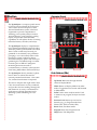
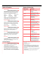
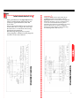
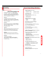
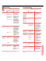
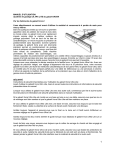
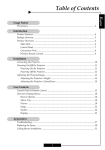
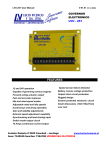
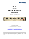
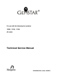
Cutler-Hammer
IQ Analyzer
START
QUICKSTART
GUIDE
CONTENTS
Introduction
4
Mounting
9
Wiring
10
Programming
12
Troubleshooting
19
IMPORTANT NOTICE
Use this Guide to begin performing basic
metering functions quickly, without reviewing
complete instructions provided in the User’s
Manual. To more fully understand the wide
array of features offered by your IQ Analyzer,
it is strongly recommended that operators
read the User’s Manual.
Following initial power-up of the IQ Analyzer,
the displayed “Meter Menu” values may not
be what is anticipated for your specific system.
The unit must first be programmed with
“General Setup” information relating to your
electrical system.
For additional information or technical
assistance, contact:
A D VANCED PRODUCT SUPPORT
CENTER 1-800-809-2772
www.cutlerhammer.eaton.com
3
Introduction
Operator Panel
(USER’S MANUAL SECTIONS 1&2)
The IQ Analyzer is a compact, panel mounted, micro-processor based device for users
who want to monitor all aspects of their
electrical distribution system. It has been
engineered to provide comprehensive
metering, power quality analysis, remote
input monitoring, control relaying, analog
inputs/outputs and communications
capabilities. It will replace dozens of existing
individual meters, recorders, and relays.
The IQ Analyzer displays a comprehensive
list of metered parameters, historical values,
harmonic profiles, peak demands and alarm
data. Custom screens may be easily programmed to conveniently view parameter
groupings, or to concurrently observe relationships as system conditions change.
Information display options and device programming are accessible through a communications port via IMPACC (Integrated
Monitoring Protection and Control
Communications), or directly at the Operator
Panel using Meter Menu and Function Keys.
The IQ Analyzer directly monitors 3-phase
lines to 600 Vac without the need for
external potential transformers. Above 600
Vac, external transformers are required.
The device complies with rigid ANSI C12.16
Class 10 revenue meter accuracy standards,
and provides true rms readings through the
50th harmonic. Accuracy is maintained in
applications with high distortion levels,
including systems exhibiting 3.0 Crest
Factor.
(USER’S MANUAL SECTION 3)
Function
LEDs
Display
Window
(F1-F4)
Previous Level
Home
Function
PBs
Meter
Menu
Up/Down
PBs
Program PB
Help PB
Push Buttons (PBs)
(USER’S MANUAL SECTIONS 3&4)
Up/Down: Maneuver through metered
values in Display Mode.
Home: Return to Display Mode from other
modes. Toggle between Current and Demand
in Meter Menu.
F1-F4: Used to enter analysis modes. Used
to maneuver in program, analysis and reset
modes.
Previous Level: Moves up one level in
hierarchy (e.g., in Program mode from
PGM/GEN/TYPE to PGM/GEN).
Reset: Enter/Exit Reset mode.
Program: Enter/Exit Program mode.
Help: Enter/Exit Help menu.
5
Modes of Operation
Displayed Information
Display Type
Comments
Current
• Phase A, B, C, Average
• Neutral
• Ground
(separate CT inputs for each)
Voltage
• Phase A-B, B-C, C-A, Average
• Phase A-N, B-N, C-N, Average
• Neutral - Ground
Power
• System1 and Phase A, B, C
• Real (Watts)
• Reactive (vars)
• Apparent (VA)
Energy
• Forward, Reverse, Net
• Real (kWh)
• Reactive (kvarh)
• Apparent (kVAh - Net only)
Demand
• System Current (A)
• System Real Power (kW)
• System Reactive Power (kvar)
• System Apparent Power (kVA)
Power Factor
•System and Phase A, B, C
•Displacement2
•Apparent3
Frequency
•Hz
•Time
•Date
% THD
Using this password protected mode, the operator
can reset or clear certain items such as Min/Max values, Alarm Triggers, Relays and Peak Demand
Values.
•Currents
Phase A, B, C
Neutral
•Voltages
Phase A-B, B-C, C-A
Phase A-N, B-N, C-N
Distortion Factor
•K-Factor4 (of Event)
• CBEMA Derating Factor5 (THDF)
•Crest Factor6
Help Mode:
Custom
•Discrete Input and Output Status
•Analog Input Reading
•User can program two screens to
display any combination of seven
Meter Menu parameters per
screen via the Custom Screens
option under Display Manager.
(PGM/DISPMGR/CUST)
Display Mode:
(USER’S MANUAL SECTIONS 5-2)
The IQ Analyzer monitors and displays a comprehensive list of metered parameters. The Meter Menu
provides easy access (using Up/Down PBs) to the
most commonly used metered parameters:
Current
Voltage
Power (Watts)
Power (Vars)
Power (VA)
Energy
Demand
Power Factor
Frequency
%THD
Distortion Factor Custom
Several parameters will require multiple screens for
complete display of all available information.
Up/Down will toggle through all displays.
Analysis Modes:
(USER’S MANUAL SECTION 5-7)
Analysis screens show detailed system information
relative to the selected category. All historical and
event information is accessed in the analysis modes.
Trend Analysis
Event Analysis
Harmonic Analysis
Demand Analysis
Program Mode:
(USER’S MANUAL SECTION 5-4)
This password protected mode is used to configure
the Unit. Use Program Mode to specify General
Setup Settings and for advanced features.
Reset Mode:
(USER’S MANUAL SECTION 5-10)
(USER’S MANUAL SECTION 5-3)
The IQ Analyzer displays various Help screens and
useful information relating to device operation, programming and troubleshooting.
Communications
(USER’S MANUAL SECTIONS 5-8)
The IQ Analyzer is an IMPACC (Integrated
Monitoring Protection and Control
Communications) compatible device. It can be
remotely monitored, controlled and programmed
when equipped with the communications option.
The small, addressable communications module
(IPONI), is mounted to the back of the IQ Analyzer.
1 Line to neutral values do not apply for 3-wire system, use sys-
tem values.
2 Fundamental watts to VA.
3 Total rms watts to VA.
4 K-Factor: A derating factor that is essentially the sum of the
squares of individual harmonic currents times the squares of
their harmonic number (i.e., multiples of fundamental). One
for each current is displayed with largest recorded in Event
metered data.
5 CBEMA Factor: A transformer harmonic derating factor defined
as a pure sine wave’s crest factor (1.414) divided by the measured crest factor.
6 Crest Factor: The ratio of peak current to rms current.
7
General
Mounting
(USER’S MANUAL SECTIONS 5-1)
When the IQ Analyzer is initially powered up, it is
in Display Mode. The “Normal LED” will blink
green and the “Current LED” will glow red. The
display will show phases A, B and C currents in
amperes for the system being monitored.
IA=
IB=
IC=
100.0
99.0
97.0
AMPERES
TRND EVNT HARM DEMD
(USER’S MANUAL SECTIONS 4-2)
The IQ Analyzer is typically mounted on an
enclosure door. This installation makes it
necessary to prepare a cutout into which the
device will be placed. Top, bottom and two
center side holes are used to mount the unit.
A flange mounting option and separate
NEMA 12/3R enclosure are available.
Contact your local distributor or sales office.
Initial Meter Menu Current Screen
The Up and Down pushbuttons (PBs) provide fast
access to other Meter Menu parameters such as
those outlined in the table. The Function pushbuttons (F1-F4) access TRND, EVNT, HARM and
DEMD from the Display Mode. These are Analysis
Modes for Trend, Event, Harmonic and Demand
information.
Note on Sign Convention
(USER’S MANUAL SECTIONS 5-22)
As a factory default, lagging vars and power factor
are represented as negative values at the load.
This is a negative sign convention consistent with
P=VI. The alternative is a power engineering convention which uses P=VI such that consumption of
power is positive. This sign convention can be
changed in the Program Mode under Power/
Energy Options in General Setup. Changing this
setting will have no effect on the unsigned “LEADING KVAR-HR” and “LAGGING KVAR-HR” energy readings. However, the “NET KVAR-HR” energy will begin counting in the opposite direction.
FLUSH MOUNT DRILLING PATTERN
Manual Capture
(USER’S MANUAL SECTIONS 5-7.2.5.12)
Capture and store system values for analysis and
to aid in verifying proper operation of the
IQ Analyzer by using Manual Capture. Enter the
Harmonic Analysis Mode from Display Mode
using the F3 Function PB. In the Harmonic
Analysis Mode, the unit captures new system measurements when the F4 pushbutton (NEW) is
pressed twice. (F3, F4, F4)
NOTE: For proper operation, an Event Trigger must be
set to Manual Capture. This can be done in the Event
Triggers section of the Program Mode.
FLANGE MOUNT DRILLING PATTERN
9
Wiring
(USER’S MANUAL SECTIONS 4-3)
Wiring installation for the IQ Analyzer must
follow a suitable Wiring Plan Drawing and
conform to applicable Federal, State and
Local codes.
Wires to the terminal blocks must not be larger than AWG No. 14. Larger wire sizes may
be used on the CT connections when using
appropriate ring terminals.
The following two figures show typical
wiring diagrams. Additional wiring diagrams
are shown in the User’s Manual.
WARNING !
Wiring procedures must be performed only by
qualified personnel who are familiar with the
IQ Analyzer and its associated electrical equipment.
Ensure that incoming ac power (or foreign power)
sources are turned off and locked out prior to
performing any electrical work. Failure to do so may
result in serious injury or death, or equipment
damage. The only exception is when connecting/
disconnecting ribbon cables at J2 or J3.
11
Programming
Quick Start Procedure
(USER’S MANUAL SECTIONS 4-5)
During initial setup of your IQ Analyzer,
use Steps 1 - 5 below after the IQ Analyzer
has been mounted and wired using Sections
4-2 and 4-3, along with Figures 4-9 to 4-34 of
the User’s Manual as a reference.
STEP #1:
Complete the General Setup Settings
Worksheet. This will require an understanding of the electrical system configuration and
transformer ratios.
STEP #2:
Enter the Program Mode of the IQ Analyzer.
If this is an initial startup, use factory default
passwords (10000 or 44444).
(Program, F2, F4)
STEP #3:
Enter General Setup Settings using the F1-F4
PBs from the information on page 13. (An
example is shown on the following pages.)
STEP #4:
Examine, understand and verify Metered
Values. Ensure display matches your system.
STEP #5:
Troubleshoot problems.
Use the guide provided, the Help Mode
and/or the User’s Manual as a reference in
troubleshooting.
General Setup Settings Worksheet
Type of system (select one)
❏ 3 Phase/4 Wire
❏ 3 Phase/3 Wire
❏ 1 Phase/3 Wire
❏ 1 Phase/2 Wire
Phase Rotation
(if Step 1 was 3 Phase, select one)
❏ ABC Rotation
❏ CBA Rotation
Choose Frequency (select one)
❏ 25Hz
❏ 40Hz
❏ 50Hz
❏ 60Hz
Incoming Line-to-Line Voltage
Enter from 100-600 Vac __ __ __
PT Primary Rating (120 volt secondary)
Enter from 120-500,000 volts
__ __ __ , __ __ __
CT Primary Rating (5A secondary)
Enter from 5-10,000A
__ __ , __ __ __
GND CT Primary Rating (5A secondary)
Enter from 5-10,000A
__ __ , __ __ __
Programming Options (select one)
❏ Faceplate Only
❏ Input3 Key Only
❏ Faceplate & IMPACC (recommended)
❏ Input3 Key & IMPACC
Energy Resolution for Wh, varh, & VAh
(select one)
❏ Kilowatt-hours
❏ Megawatt-hours
Var Sign Convention (select one)
❏ Lagging vars & PF negative at load
❏ Lagging vars & PF positive at load
Date and Time
Enter date and time if required
__________________
Change Password
Enter new 5 digit password if required
__ __ __ __ __
13
Programming Example
(USER’S MANUAL SECTION 6)
Meter a typical load on a 480 volt, 3 phase 3 wire
(ABC phase rotation), 60Hz system with 1200/5
CTs, 50/5 ground CTs and no PTs. (Assume
Kilowatt-hour energy resolution, and lagging vars
& Power Factor negative at load.)
NOTE: The IQ Analyzer must be programmed to
a PT ratio of 120/120 or unity for the IQ Analyzer
to recognize there are no PTs.
From Main Menu
Press and Release
Program PB
Top Level Entry
Screen Displayed
Press Up (F2), then
Enter (F4) to input
default password
10000
Incorrect
Password Exits
Program Mode
Automatically
Program Mode
Top Level Menu
Displayed
General Setup
Blinking
Press and Release
Select (F1) PB
Type of System
Blinking
Press and Release
Select (F1) PB
Choose Type of
System with
Parameters
Displayed
Use F1-F3 PBs to
Move an Select
3 Phase/3 Wire
Phase Rotation with
Parameters Displayed
PGM-MAIN
LAST PROGRAMMED:
6/11/97 11:48:07A
INCOM ADDR:000
SOFTWARE VER. 1.14
ENTER PASSWORD:00000
(00000=VIEW ONLY PW)
--> UP DOWN ENTER
PGM
CHOOSE CATEGORY:
GENERAL SETUP
ANALOG INPUTS
ANALOG OUTPUTS
DISCRETE INPUTS
EVENT TRIGGERS
SEL UP DOWN ENTER
PGM/GEN
SELECT PARAMETER:
TYPE OF SYSTEM
FREQUENCY
INCOMING L-L VOLTAGE
PT PRIMARY RATING
CT PRIMARY RATING
SEL UP DOWN PGDN
PGM/GEN/TYPE
3 PHASE/4 WIRE
*3 PHASE/3 WIRE
SINGLE PHASE/3 WIRE
SINGLE PHASE/2 WIRE
Use (F2) or (F3) PBs to
Move to Incoming
Line-Line Voltage
Press and Release
Select (F1) PB
L-L Voltage
Rating with
3 Digits
Displayed
Use F1-F4 PBs to
Establish and Enter
480 Volts
Incoming
L-L Voltage
Blinking
Use F2-F4 PBs
to Move to
PT Primary Rating
PT Primary
Rating Blinking
Press and Release
Select (F1) PB
PT Primary
Rating with
6 Digits
Displayed
Use F1-F4 PBs
to Establish and
Enter 120 Volts
PT Primary
Rating Blinking
Use F2-F4 PBs
to Move to
CT Primary Rating
CT Primary
Rating Blinking
Press and Release
Select (F1) PB
CT Primary
Rating with
5 Digits
Displayed
SEL UP DOWN
PGM/GEN/TYPE/3PH3W
*ABC - PHASE ROTATION
CBA - PHASE ROTATION
Incoming L-L
Voltage Blinking
Use F1-F4 PBs to
Establish and
Enter 1200 A
CT Primary
Rating Blinking
Use F2-F4 PBs
to move to GND
CT Primary Rating
GND CT
Primary
Rating Blinking
Press and Release
Select (F1) PB
GND CT
Primary Rating
with 5 Digits
Displayed
Use F1-F4 PBs to
Establish and
Enter 50 A
GND CT
Primary
Rating Blinking
PGM/GEN/INVOLT
INCOMING L-L VOLTAGE
APPLIED TO VOLTAGE
INPUT TERMINALS A,B,
C, N OF IQ ANALYZER
(100 TO 600 VAC):
480
--> UP DOWN ENTER
PGM/GEN/PT
PT PRIMARY L-L RATING
120 TO 500,000 V
(SEE USER’S MANUAL IF
NOT USING 120V
SECONDARY PTS)
000120:120
--> UP DOWN ENTER
PGM/GEN/CT
CURRENT TRANSFORMER
PRIMARY RATING:
5 TO 10,OOO AMPS
(MUST BE 5 AMP
SECONDARY CT)
01200:5
--> UP DOWN ENTER
UP DOWN ENTER
Use F2-F4 PBs to
Move and
Enter ”ABC”
Type of System
Blinking
Use (F2) or (F3) PBs
to Move to
Frequency
Frequency
Blinking
Press and Release
Select (F1) PB
Frequency
Choices
Displayed
Use F2-F4 PBs to
Move to and Enter
60Hz
Type of System
Blinking
continued on next page
PGM/GEN
SELECT PARAMETER:
TYPE OF SYSTEM
FREQUENCY
INCOMING L-L VOLTAGE
PT PRIMARY RATING
CT PRIMARY RATING
SEL UP DOWN PGDN
PGM/GEN/FREQ
25 HZ
40 HZ
50 HZ
* 60 HZ
UP DOWN ENTER
PGM/GEN
SELECT PARAMETER:
TYPE OF SYSTEM
FREQUENCY
INCOMING L-L VOLTAGE
PT PRIMARY RATING
CT PRIMARY RATING
SEL UP DOWN PGDN
Press Program
PB to exit
Program Mode
PGM/GEN
SELECT PARAMETER:
FREQUENCY
INCOMING L-L VOLTAGE
PT PRIMARY RATING
CT PRIMARY RATING
GND CT PRIMARY RATING
SEL UP DOWN PGDN
PGM/GEN/GCT
GND CURR TRANSFORMER
PRIMARY RATING:
5 TO 10,000 AMPS
(MUST BE 5 AMP
SECONDARY CT)
00050:5
--> UP DOWN ENTER
PGM/GEN
SELECT PARAMETER:
FREQUENCY
INCOMING L-L VOLTAGE
PT PRIMARY RATING
CT PRIMARY RATING
GND CT PRIMARY RATING
SEL UP DOWN PGDN
15
Time/Date Programming Example
From Main Menu
Press and Release
Program PB
Use F1-F3 PBs to
Move and Select
Parameter to Change
Top Level Entry Screen
Displayed
Parameter Digit
Blinking
Password Programming Example
From Main Menu
Press and Release
Program PB
Use F1-F4 PBs to
Move and Select
Change Password
Top Level Entry Screen
Displayed
5 Digit Password
Displayed
Press Up (F2), then
Enter (F4) to input
default password
10000
Use F1-F4 PBs to
Establish and Enter
New Password
Press Up (F2), then
Enter (F4) to input
default password
10000
Use F1-F4 PBs to
Establish and Enter
Desired Data
Incorrect Password Exits
Program Mode
Automatically
Parameter
Blinking
Incorrect Password Exits
Program Mode
Automatically
Press Program
PB to Exit
Program Mode
Program Mode
Top Level Menu
Displayed
Program Mode
Top Level Menu
Displayed
General Setup
Blinking
Press and Release
Select (F1) PB
Type of System
Blinking
Changed Password
Blinking
Press Program
PB to Exit
Program Mode
General Setup
Blinking
Press and Release
Select (F1) PB
Type of System
Blinking
Use F1-F4 PBs to
Move and Select
Change Date/Time
Month
Blinking
17
Troubleshooting
oubleshooting
(USER’S MANUAL SECTIONS 7)
ymptom
Operator Panel
icator LED’s
off.
Probable Cause
Possible Solutions(s)
Line voltage level is
deficient.
• Locate cause of deficiency in ac line.
• Locate deficiency in
the ac control power
line.
• Verify that the ac line
(and/or PTs) are wired
properly.
• Verify line voltage
with multimeter.
Check power module
fuse(s) on affected
phase(s). These are
located just above voltage inputs (behind the
cover of power module). Reseat or replace
fuse(s) as necessary.1
Separate source control power is deficient.
ac line connections (or
optional external PTs)
are not properly
wired.
Blown or loose fuse(s).
ne or more voltge phases read
ncorrectly.
Blown or loose
fuse(s).
Incorrect voltage
settings.
ower parameters
Watt, var, VA,
ower Factor)
ead incorrectly.
Phasing for voltage
and current is mismatched.
CT polarity is
reversed.
ncorrect readings
n one or more
urrents.
Incorrect current
transformer ratio setting.
•Verify line voltage with
multimeter. Check
power module fuse(s)
on affected phase(s)
located just above the
voltage inputs behind
the cover of power
module. Reseat or
replace fuse(s) as
necessary. 1
• Verify correct settings
programmed in the IQ
Analyzer for system
type,L-L voltage and
PT rating.
• Capture an event and
compare phase angles
of Va, Vb, Vc, Ia, Ib, Ic
to detect possible
wiring error(s).
• Verify connections per
wiring diagrams.
• Reverse CT leads.
Verify proper wiring
and grounding.
• Verify incoming current using a separate
ammeter.
• Verify proper CT ratio
settings.
• Check CT wiring and
grounding.
Power Module Fuse: Buss KTK-R-3/4 or equivalent (3/4 amp).
18
(USER’S MANUAL SECTIONS 7)
Unit displays:
“Hardware Failure”
“Register Failure”
“Multiply Failure”
“Divide Failure”
“Logic Failure”
“Add/Subtract
Failure”
Possible IQ Analyzer
hardware failure.
•Reboot Unit by
mometarily removing
power cable at connector
J2.
•Replace Unit.
Unit displays:
“Internal RAM
Error”
“External RAM
Error”
“External ROM
Error”
IQ Analyzer hardware
error.
•Reboot Unit.
•Replace Unit.
Unit displays:
“Reverse Sequence”
IQ Analyzer has detected phasing difference
between programmed
setpoint and actual system parameters.
•Verify actual system
phasing. Capture an
event and compare
phase angles of Va, Vb,
Vc, Ia, Ib, Ic to detect
possible wiring error(s).
• Verify that IQ Analyzer
setpoint matches actual
system phasing.
• Verify IQ Analyzer connections.
Unit fails to capture
Harmonic Data
when Manual
Capture is pressed.
No manual capture
event trigger has been
programmed.
• Enter Program Mode
and set up an Event
Trigger for Manual
Capture.
Unit fails to communicate over
IMPACC network.
Wrong or conflicting
address set on IPONI.
• Check that IPONI has a
unique address on the
system and that software is addressing
proper unit.
• Check input/output fuse
adjacent to IQ Analyzer
communication connector. Replace if
necessary.1
• Verify wiring is in conformance with IMPACC
wiring rules.
Blown fuse on
IQ Analyzer.
Communications
wiring error.
IPONI failure.
Display goes blank
after several minutes.
Display Manager
Screen Saver Option is
set to blank rather than
dim.
• Press any pushbutton to
activate display.
• Program longer timeout
in Meter Menu Return
Time in Display
Manger.
Unit setpoints
unchanged upon
exiting program
mode.
Unit was in
View-Only mode using
password (00000).
• Re-enter program
setpoints using proper
password. Customer
established or factory
default (44444 or 10000).
1 I/O Fuse: Littlefuse Plug-in Microfuse, Catalog #273.250, 0.25A, 125V or
equivalent.
19
Cutler-Hammer
For additional information or technical assistance, contact:
ADVANCED PRODUCT
SUPPORT CENTER 1-800-809-2772
www.cutlerhammer.eaton.com