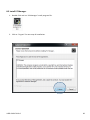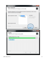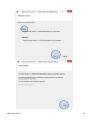
1
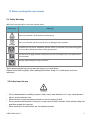
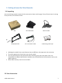
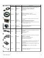
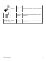
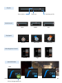
User’s Guide HD Drive Recorder USER GUIDE V1.0.0 1 Table of Contents 1. GLOSSARY ..................................................................................................................................................4 2. BEFORE READING THIS USER MANUAL ........................................................................................................5 2.1 SAFETY WARNINGS ....................................................................................................................................................5 2.2 SAFETY ITEMS FOR USE ...............................................................................................................................................5 3. GETTING TO KNOW THE DRIVE RECORDER ..................................................................................................7 3.1 UNPACKING ..............................................................................................................................................................7 3.2 EXTRA ACCESSORIES ...................................................................................................................................................7 3.3 LOCATION OF CONTROLS...........................................................................................................................................10 4. GETTING READY TO START RECORDING..................................................................................................... 11 4.1 TO INSERT A MEMORY CARD ......................................................................................................................................11 4.2 TO EJECT A MEMORY CARD ........................................................................................................................................11 4.3 SELECTING A SUITABLE MEMORY CARD (NOT SUPPLIED) .................................................................................................13 5. INSTALLATION .......................................................................................................................................... 15 5.1 EMPLACE DR ..........................................................................................................................................................15 5.2 VEHICLE FUSE CONNECTING FOR POWER SUPPLY ..........................................................................................................19 5.3 ADJUSTMENT CAMERA ANGLE ..................................................................................................................................20 5.4 JOINT TAMPERPROOF KIT ..........................................................................................................................................21 6. RECORDING.............................................................................................................................................. 23 6.1 VIDEO RESOLUTION ..................................................................................................................................................23 6.2 OVERLAY INFORMATION ...........................................................................................................................................23 6.3 USAGE OF MEMORY.................................................................................................................................................27 6.3.1 Directory of NORMAL movie file area..........................................................................................................28 6.3.2 Directory of EVENT movie file area ..............................................................................................................28 6.3.3 Directory of EMERGENCY movie file area ....................................................................................................28 6.3.4 Directory of LOG area ..................................................................................................................................28 6.4 FILE NAME RULE ......................................................................................................................................................30 6.5 CYCLE RECORDING ...................................................................................................................................... 32 6.6 IR RECORDING ............................................................................................................................................ 32 6.7 RECORDABLE TIME...................................................................................................................................... 32 7. LED SIGNAL ................................................................................................................................................. 34 7.1 IN-CABIN LEDS PATTERN...........................................................................................................................................34 8. PC MANAGER ............................................................................................................................................... 35 8.1 SYSTEM REQUIREMENT .............................................................................................................................................35 8.2 INSTALL PC MANAGER .............................................................................................................................................36 8.3 UNINSTALL PC MANAGER .........................................................................................................................................41 8.4 GUI INFORMATION ..................................................................................................................................... 43 8.5 ICON INFORMATION ................................................................................................................................... 44 8.5.1 Control Panel ...............................................................................................................................................44 8.6 SETTING CONFIGURATION........................................................................................................................... 50 8.6.1 Record setting ..............................................................................................................................................51 8.6.2 Event setting ................................................................................................................................................52 8.6.3 Time setting .................................................................................................................................................53 8.6.4 User setting..................................................................................................................................................54 USER GUIDE V1.0.0 2 8.6.5 Storage setting ............................................................................................................................................55 8.6.6 Etc. (Other settings) .....................................................................................................................................56 9. SPECIFICATIONS ............................................................................................................................................ 57 10. WARRANTY ................................................................................................................................................ 60 USER GUIDE V1.0.0 3 1. Glossary DR Drive Recorder UTC Coordinated Universal Time RTC Current Regional Time RTC=UTC + Offset time Offset times are defined in each region and applying summer time is capable. DST Daylight Saving Time External Device It’s any equipment and application which connects to DR via USB. For example, Android or Window terminal. Specific Number This indicator includes a DR’s serial number and firmware version. ALT Alternative Ref Reference NA Not Available Effective Pixel Count Unlike the total pixel count, this is the actual number of pixels used to capture an image. Quality An expression of the rate of compression used in a digital image. Higher quality images have a lower rate of compression, which usually results in a larger file size. Resolution The number of pixels present in a digital image. High resolution images contain more pixels and typically show more detail then low resolution images. USER GUIDE V1.0.0 4 2. Before reading this user manual 2.1 Safety Warnings What the icons and signs in this user manual mean: Safety Icon Meaning There is a potential risk of death or serious injury. There is a potential risk of personal injury or damage to the product. To reduce the risk of fire, explosion, electric shock, or personal injury when using your drive recorder, follow these basic safety precautions. Here are hints or page number references you will find helpful when you operate the drive recorder. Settings required before using a function. These warning signs are here to prevent injury to you and others. Please follow them explicitly. After reading this section, Keep it in A safe place for future reference. 2.2 Safety items for use * Do not disassemble or modify s product under user's own discretion, or it may cause product failure, electric shock or fire. * When service is required please contact our service center for A/S. * Do not operate the terminal in driving or it may cause a traffic accident. Park vehicle safely first and then operate the terminal. * When terminal is in malfunction, do not operate terminal. USER GUIDE V1.0.0 5 * If foreign matter or water gets into terminal or smoking, stop using and contact service center for A/S. * When other electronic product is installed in vehicle, be careful that terminal power cable is cut or gets damaged, or it may cause product failure or electric shock or fire. * When service is required, please contact our service center for A/S. * Do not change the terminal installation location without authorization, or there may be blind area in image photography and user shall be liable on this. * Fuse shall be in rated capacity. * Unauthorized installation may cause failure in vehicle or product. * When power is connected, do not remove SD card, cause card failure. * Do not touch SD card with oily or wet hand, or it may cause product failure. * Do not put foreign material into card insertion slot of the terminal, or card may not be inserted or it may cause product failure. * When using the cigar jack power cable as a source of power for the unit, ensure a proper connection. * An improper connection could result in loss of data or card defect. * For cleaning, do not use water, benzene or alcohol to DR and parts. * Please use soft and dry cloth, or it may cause product failure. * Do not apply strong impact to the terminal, or terminal may break by the impact or it may cause product failure. * Please use only authenticated card and recommended card, or it may cause data loss. * When cigar jack is used, please avoid poor contact, or poor contact may cause data loss and card failure. * GPS module requires warming up time for initial start up. It may take several seconds or several minutes after power is turned on according to receiving environment. * Metallic coating on front window of vehicle may cause communication trouble in receiving GPS receiving. * Vehicle with tinted front window may experience communication errors. * Be careful for In-Cabin camera angle not to be shaded by inside room mirror when the DR install. * Adhere after working Air Drier (Air Conditioner) in case of much humidity. * After connected power cable with the DR, the state of recording after start processing is completed. * Do not touch to camera lens. Finger prints are may cause unclear recorded video quality. USER GUIDE V1.0.0 6 3. Getting to know the Drive Recorder 3.1 Unpacking Your new driving recorder comes with the accessories shown on this page. If any of these items is missing from your box, call customer center. Box Tamperproof Kit Drive Recorder DC Fuse Power Cable GPS & Cradle Cable fixing tie & Clips Although the models have some features that are different, they operate in the same way. The exact appearance of each item may vary by model. You can purchase parts and accessories after consulting with your local dealer. DR is not responsible for reduced malfunctions caused by any unauthorized use of accessories such as the power cable etc., Micro SDHC memory card are not included. 3.2 Extra Accessories USER GUIDE V1.0.0 7 Image Model No. Descriptions GPSA-6000 External GPS Antenna GPS antenna is able to connect to the GPS Cradle and provides for more accurate GPS polling. Cable length is 6 meters, magnet type. IP67 Rated. VC04701-R Rear view Camera. CMOS D1(720x480p) rear camera 6 meters’ cable length, Backer signal support Korea Origin RCAM-9990IR Rear view Camera.(Truck) The DR is compatible with an additional camera to cater for the recording of an additional angle (e.g. rear or fuel camera) Camera cable length of up to 22 meters IP67, 150° wide angle lens, infrared Automatically displays the rear camera when reverse is selected and VOC is in use RCAM-9220NR Rear view Camera.(Truck) Rear Camera cable length is around 22 meters for HD truck. IP67 grade, 170(d) wide angle. Back-gear signal output. VOC-300 Video Out cable Real-time video can be displayed on an in-cabin LCD monitor via the Video-Out port (PAL/NTSC compatible). RCA Male. 1-meter cable length. UL Approved. AV monitor 7” wide LCD monitor (16:9) to display real-time video incabin. Resolution RGB 800x480. Automatic brightness adjustment. Adjustable mounting options. FS-10M SOS Foot S/W SOS Foot Switch is designed to enable the driver to discreetly trigger an event/alarm recording that will be received in a control room or emergency services department. Discreet alternative to pushing the event button on the main device. IP 54 steel construction, 5 meters’ cable length. 10A / 250VAC YCB-100 Y-Type Cable If use SOS Foot S/W and Video-out cable any once then This Y-type cable is necessary. MT-701 USER GUIDE V1.0.0 Part Name 8 USER GUIDE V1.0.0 WF-700RA Wireless LAN USB Adaptor Wi-Fi(Wireless LAN) adaptor for internet communications. LT-600 Wireless 3G/LTE USB Modem International telecommunication specification support. SIM card use. USB-EX2M USB Extension cable(M-F) 2 meter USB cable for external USB flash memory use. Right-L angle type. 9 3.3 Location of Controls GPS Receiver Module (GNSS Worldwide) Window Cradle Flame retardant material In-cabin view camera Operation LED Angle hook for Tamperproof case Road view camera (Six-element lens) [Picture 1] Out side of vehicle view External GPS antenna port 3rd Camera port GPS port USB 2.0 DC / Power Micro USB Video-out Manual Recording button Infrared LEDs In-cabin view camera [Picture 2] Inside of vehicle view USER GUIDE V1.0.0 10 4. Getting ready to start recording 4.1 To insert a memory card 1) Turn the drive recorder off. 2) Open the memory card cover as shown in the figure. 3) Insert the memory card into the card slot until it softly clicks. * Make sure that the drive recorder is placed as shown above and the terminal portion of the card is facing up. 4) Close the cover. Inserting and ejecting a memory card (Not Supplied) 4.2 To eject a memory card 1) 2) 3) 4) Turn the drive recorder power off. Open the memory card cover as shown in the figure. Gently push the memory card to eject it. Pull the memory card out of the memory card slots and close the cover. To avoid data loss, turn off the drive recorder by removed the power cable before inserting or ejecting the memory card. Be careful not to push the memory card too hard. The memory card may suddenly pop out. If you eject the memory card from the drive recorder while it is on, the drive recorder turns off. Your drive recorder supports only micro SDHC and SDXC cards. Card compatibility with this drive recorder may vary depending on the card manufacturer and type. USER GUIDE V1.0.0 11 4.3 Selecting a suitable memory card (Not supplied) COMPATIBEL MEMORY CARDS You can use micro SDHC, and SDXC cards with this drive recorder. We recommend you use an SDHC, SDXC card. This drive recorder supports SDHC, SDXC cards up to 64GB. We cannot guarantee normal operation with SDHC cards bigger than 64GB. MMC (Multi Media Card) and MMC Plus are not supported. Compatible memory card capacity: - SDHC: 4GB~ 32GB - SDXC: ~up to 64GB When you use unauthorized memory cards, the driving recorder can not record videos correctly and your recordings may be lost. The memory cards released after this drive recorder was released may not be compatible with the camcorder. To ensure stable recording and playback, use 20MB/s (Class 10) or higher memory cards. (MLC/Multi Level Cell) Type memory card is recommended) SDHC/SDXC cards are a higher version of SD memory cards and support higher capacities than SD memory cards. Using the memory card adaptor To use a micro memory card with a computer or a card reader you must attach it to or insert it into an adaptor. HANDLING A MEMORY CARDS Damaged data may not be recoverable. We recommend you make a back-up of important data separately on the hard disk of your PC. Turning the power off or removing a memory card during an operation such as formatting, deleting, recording, and playback may cause data loss. If you modify the name of a file or folder stored in the memory card with your PC, your drive recorder may not recognize the modified file. The memory card does not support any data recovery mode. Therefore, care should be taken to prevent the memory card from being damaged while recording. A memory card has a certain life span. If you cannot record new data, you have to purchase a new memory card. Do not bend, drop, or subject the card to strong impacts. Do not place foreign substances on the memory card terminals. Use a soft dry cloth to clean the terminals if required. Do not paste anything other than the label provided with the card on the label pasting area of the card. Do not use a damaged memory card. USER GUIDE V1.0.0 13 Be careful to keep the memory card out of the reach of children, who might swallow it. The camcorder supports micro SDHC, and SDXC memory cards, giving you a wider choice of cards! The data storage speed of cards may differ, depending on the manufacturer and production system. • MLC (multi level cell) system: faster write speed enabled. • TLC (Triple level cell) system: only lower write speed is supported. For best results, we recommend using a memory card that supports a faster write speed. Using a lower write speed memory card for recording video may cause difficulties when storing. We are not responsible for data loss due to misuse, including loss caused by any PC virus. We recommend using a memory card case to avoid data loss that can be caused by moving the card or by static electricity. After a period of use, the memory card may get warm. This is normal and is not a malfunction. USER GUIDE V1.0.0 14 5. Installation 5.1 Emplace DR Center of Windshield Insert micro SD cards USER GUIDE V1.0.0 Adhere after working Air Drier (Air conditioner) in case of much humidity. 15 Remove tape film at adhered area of cradle. Install DR on windscreen front of rear view mirror. Click! Please make sure that joint DR with cradle safety. Connect to GPS cable jack USER GUIDE V1.0.0 Connect to DC Power cable jack 16 DR is designed multi direction cradle for all type of vehicle installation. Please refer to below figure out for your right installation for video angle fit. Refer to installation angle guide to backside of cradle. USER GUIDE V1.0.0 17 Put the power code cable into the windscreen and the roof inside. Continue to put the power cord cable to the side. Put the power cord cable to the driver seat’s door inside. Fit the power cord cable to along the door frame inside. USER GUIDE V1.0.0 18 5.2 Vehicle FUSE connecting for power supply Open the fuse box and find out power terminal for all time supplying power as like Button type trunk, Emergency lamps, In-Cabin lights, etc., Properties of Fuse informations are located backside of fuse cover in vehicle) * Fuse box location may vary difference each vehicle type. Connect plus terminal cable (RED color) to lead tap of Fuse. Connect minus terminal (BLACK color) to bolt or metal frame of vehicle. * If power cable has connected to fuse of consistently supplying power then it may cause drain battery of vehicle. USER GUIDE V1.0.0 19 Safety Precautions Do not install the product or adjust volume while driving as it might cause a vehicle accident. If there is a smoke or strange smell coming from the cigar socket, then stop using the product immediately and visit service center or your dealer. Dusts in the cigar socket can cause a heat or fire. Please clean the dusts it before use. Check often if the main device is properly installed. Vibration can lead to disconnection and it might cause personal injury or damage of the product. We are not liable for any kind of accidents occurred while using or careless handling of the product. Please keep in mind that any injuries caused by the customers will be their sole responsibility. 5.3 Adjustment camera angle Adjusting angle of cameras. Remove lens cover Be careful for lens not to be touched by fingerprint or contaminated material . USER GUIDE V1.0.0 20 5.4 Joint Tamperproof Kit Fit tamperproof case’s tap to camera angle’s hole for adjust angle. USER GUIDE V1.0.0 21 Joint Tamperproof case with GPS cradle’ clip. Lock the bolt to tamperproof case by wrench. USER GUIDE V1.0.0 22 6. Recording 6.1 Video resolution The DR has two (2) built in high-definition HD CMOS image sensors and are made of glass for an optimal lens and optimal video quality. The glass lens has better all round performance than a plastic lens especially in high temperature environment. The DR records 1280x720p resolution for Front and In-Cabin view. 6.2 Overlay information [Figure 6.2.1 / Information overlaid on Front Video] USER GUIDE V1.0.0 23 [Table 6.2.1 / Descriptions of information overlaid on Front Video] ①Camera View “ Front” is overlaid External Device can select 3 kinds of overlay time information. The time information is selected by configuration update which is explained as “Overlay Time”. [Case1 : ONLY RTC is overlaid] When Summer time is off, the below words is displayed. RTC [YYYY:MM:DD - HH:MM:SS] When Summer time is on, the below words is displayed. DST [YYYY:MM:DD - HH:MM:SS] ②Time Information [Case2 : ONLY UTC is overlaid] UTC [YYYY:MM:DD - HH:MM:SS] [Case3 : BOTH RTC&UTC are overlaid] When Summer time is off, the below words is displayed. RTC [YYYY:MM:DD - HH:MM:SS] UTC [YYYY:MM:DD - HH:MM:SS] When Summer time is on, the below words is displayed. DST [YYYY:MM:DD - HH:MM:SS] UTC [YYYY:MM:DD - HH:MM:SS] ③GPS Coordinates When DR cannot receive GPS data, each of the value filed is inserted as “-”. ④Speed GPRMC’s “Speed in knots” field value received from GPS module is displayed in this “Speed” value filed. The unit of this value must be converted from “knot” to “km/h”, because the unit of speed received from GPS module is “knot”. This value isn’t displayed up to the decimal point. [km/h] unit is displayed next to this value field. If GPS module linked with DR is connected to vehicle and can get vehicle speed pulse, the GPRMC’s “Speed in knots” field has vehicle speed converted from the pulse. If GPS module cannot get vehicle speed pulse, GPRMC’s “Speed in knots” field has “speed over the ground in knots” detected by the GPS module. ⑤G-Sensor Each vale is displayed up to the decimal point second place. values(Gx, Gy, Gz) The section shows procedures regarding X-axis value Gx, Y-axis value Gy and Z-axis value Gz. USER GUIDE V1.0.0 24 [ Figure 6.2.2 / Information overlaid on In-cabin Video ] [Table 6.2.2 / Descriptions of information overlaid on IN-CABIN Video] ①Camera View “ IN-CABIN” is overlaid ②Time Information This field has the same value as Table 6.2.1 USER GUIDE V1.0.0 25 [Figure 6.2.3 / Information overlaid on rear video] RTC [2015:03:26 - 19:58:47] REAR [Table 6.2.3 / Descriptions of information overlaid on REAR Video] ①Camera View “ REAR” is overlaid ②Time Information This field has the same value as Table 6.2.1 USER GUIDE V1.0.0 26 6.3 Usage of Memory The drive recorder prepares 4 types of directories and system margin area in Primary SDHC and Secondary SDHC slot. Secondary memory slot Primary memory slot USER GUIDE V1.0.0 Primary memory slot Secondary memory slot 27 6.3.1 Directory of NORMAL movie file area Allocate 84% in primary SD Memory, 95% in secondary SD memory. Drive recorder stores the all-time 60 seconds’ movie files in NORMAL movie area. When movie files reached full capacity of NORMAL movie file area in one SD memory, Drive recorder starts to store NORMAL movie files in NORMAL movie file area of another SD memory. When it reached full capacity of NORMAL movie area in both SD Memories, Drive recorder should overwrite all-time movie files in this area (delete the oldest file and store the new file). 6.3.2 Directory of EVENT movie file area Allocate 10% in primary SD memory. DR stores the accident 30 seconds movie file in EVENT file area. Although Drive recorder depletes capacity of Event Move File area in primary SD, DR will overwrite EVENT Movie files stored in the area. When this case occurs, even if EVENT occurs Drive recorder must not record new EVENT Movie file in Event Movie File area of primary SD. Drive recorder is record file names of Accident-Event-Log files to CSV format. 6.3.3 Directory of EMERGENCY movie file area Allocate area to with NORMAL movie file area. DR stores the accident 30 seconds movie file in EMERGENCY file area. Although Drive recorder depletes capacity of EMERGENCY Move File area in primary SD, DR will not overwrite EMERGENCY Movie files stored in the area. When this case occurs, even if Emergency occurs Drive recorder must not record new EMERGENCY Movie file in Event Movie File area of primary SD. Drive recorder is record file names of Accident-Event-Log files to CSV format. 6.3.4 Directory of LOG area Allocate 1% in primary SD memory. Drive recorder should store Event Logs and Sensor Logs in this area. Drive recorder stores Accident Event Log. Drive recorder stores GPS data received from GPS module. Drive recorder records GPS data as a CSV format. A GPS Log can be up to 1MB. If this log file becomes 1 MB, Drive recorder should close this log file and open new log file to record GPS data continuously. Drive recorder is stores G-Sensor data detected by the Drive recorder in 20[Hz] as G-Sensor Log. Drive recorder is records G-Sensor data as a CSV format. A G-Sensor Log can be up to 1MB. If this log file becomes 1 MB, Drive recorder should close this log file and open new log file to record G-Sensor data continuously. Whenever Drive recorder starts-up system check the recorded dates of GPS Logs and G-Sensor Log. USER GUIDE V1.0.0 28 [Figure 6.3.4-1 Log File / Accident-event] [Figure 6.3.4-2 Log File / G-Sensor] USER GUIDE V1.0.0 29 [Figure 6.3.4-3 Log File / GPS] If one SD memory was inserted in only Primary SD memory slot of Drive recorder, Drive recorder operates according to the allocation of Primary SD slot If one SD memory was inserted in only Secondary SD memory slot of Drive recorder, Drive recorder operates according to the allocation of Primary SD slot. NORMAL movie file area and EVENT movie area are prepared in the SD memory. 6.4 File name rule User is able to select file naming rule which is used while Drive recorder’s naming a movie file. 1. User selects file naming rule on External Device’s display. (Extra) 2. External Device informs user’ selection to Drive recorder by inserting configuration file. - If user selects “UTC”, File Naming Rule filed of configuration file has an indicator of UTC. USER GUIDE V1.0.0 30 - If user selects “RTC”, File Naming Rule filed of configuration file has an indicator of RTC. 3. Drive recorder starts to name movie files with compliance with configuration. If Drive recorder receives selection of “UTC”, Drive recorder should name movie files using UTC as “UTCYYYYMMDD_HHMMSS.avi”, where “UTC” is indicated as using UTC time. - “YYYY” is indicated as current YEAR, “MM” is indicated as current MONTH, “DD” is indicated as current DAY, “HH” is indicated as current HOUR, “MM” is indicated as current MINUTE, “SS” is indicated as current SECOND. If Drive recorder receives selection of “RTC”, Drive recorder should name files using RTC as “RTCYYYYMMDD_HHMMSS.avi”, where “RTC” is indicated as using RTC time, - “YYYY” is indicated as current YEAR, “MM” is indicated as current MONTH, “DD” is indicated as current DAY, “HH” is indicated as current HOUR, “MM” is indicated as current MINUTE, “SS” is indicated as current SECOND. Data file Recorded Folder in SD memory Example of File Name NORMAL Movie File /NORMAL/”each folder including 20 files” UTC20160726_020010.kds RTC20160726_020011.kds Event Movie File /EVENT EVENT_UTC20160726_020010_E.kds EVENT_RTC20160726_020010_G.kds EMERGENCY Movie File /EMERGENCY EMERGENCY_UTC20160726_020010_E.kds EMERGENCY_RTC20160726_020010_G.kds PARK Movie File /PARK PARK_RTC20160726_020010_E.kds Event Log Accident Event /LOG Log Accident-event-log.csv GPS Log /LOG/GPS GPS_UTC20160726_020010.csv GPS_RTC20160726_113006.csv G-Sensor Log /LOG/G-Sensor G-Sensor_UTC20160726_020010.csv G-Sensor_RTC20160726_113006.csv Sensor Log [ Table 6.4 / Drive recorder’s recording data file] USER GUIDE V1.0.0 31 6.5 Cycle recording During normal operation the video files are saved in 60 second intervals. If the capacity of the micro SDHC card runs short, the files will be overwritten from the oldest to newest. EMERGENCY files will not be overwritten. (factory default). It is able to be changed configuration via PC manager setting. 6.6 IR Recording The DR with IR is designed to operate in zero light environments. Wide angle IR distribution ensures that the in-cabin camera produces high quality video no matter what the environment light levels. 6.7 Recordable Time Normal Quality 2 Channel - PRIMARY Memory / Sound OFF Video Frame/s 4 fps 5 fps 10 fps 15 fps 30 fps 16GB 22h 15m 18h 59m 9h 20m 6h 15m 3h 17m 32GB 43h 29m 37h 17m 18h 40m 11h 50m 6h 34m 64GB 99h 14m 85h 12m 42h 13m 26h 33m 14h 53 Normal Quality 2 Channel - PRIMARY Memory / Sound ON Video Frame/s 4 fps 5 fps 10 fps 15 fps 30 fps 16GB 16h 43m 14h 60m 8h 14m 6h 15m 3h 37m 32GB 33h 26m 29h 21m 16h 28m 11h 50m 6h 34m 64GB 75h 24m 67h 28m 37h 29m 26h 33m 13h 59m Normal Quality 3 Channel - PRIMARY Memory / Sound OFF Video Frame/s 4 fps 5 fps 10 fps 15 fps 27 fps 16GB 29h 21m 23h 59m 12h 35m 8h 33m 4h 38m 32GB 58h 41m 47h 18m 24h 30m 16h 26m 8h 37m 64GB 134h 16m 108h 03m 54h 72m 36h 32m 18h 24m USER GUIDE V1.0.0 32 Normal Quality 3 Channel - SECONDARY Memory / Sound ON Video Frame/s 4 fps 5 fps 10 fps 15 fps 27 fps 16GB 20h 18m 18h 09m 10h 22m 7h 13m 4h 16m 32GB 39h 57m 35h 38m 20h 44m 14h 26m 7h 51m 64GB 91h 01m 81h 03m 47h 21m 33h 06m 17h 20m (Unit: Approximate hour of recording in “NORMAL” folder) Your recordable time and capacity may differ from the figures in the tables depending on your subject and actual recording conditions. The higher the resolution, the more memory is used. Lower resolution increases the recording time, but the image quality may suffer. The bit rate automatically adjusts to the recording image. Accordingly, the recording time may vary. Memory cards bigger than 64GB may not operate normally. 1GB ≒ 1,000,000,000 bytes : Actual formatted capacity may be less as the internal firmware uses a portion of the memory. USER GUIDE V1.0.0 33 7. LED Signal 7.1 In-cabin LEDs pattern Operating state LED Signal Operating state System Booting Connecting External ( Approx. 5 sec.) Device (Wi-Fi/3G/4G) Re-Booting (Approx. 20 sec.) Firmware Updating (Approx. 40 sec.) Normal Recording LED Signal Not inserted memory card / Entering CCTV mode GPS signal detected Event recording (Approx. 15 sec.) : LED LAMPs Blinking state USER GUIDE V1.0.0 34 8. PC Manager 8.1 System Requirement Your computer must meet the following requirement to run PC Manager. Items System Requirements OS Microsoft Windows XP SP2, Windows Vista, Windows 7, Windows 8 or higher CPU Intel Core 2 Duo 1.66 GHz or higher is recommended AMD Athlon™ X2 Dual-Core 2.2 GHz or higher is recommended (Notebook: Intel Core2 Duo 2.2GHz or AMD Athlon X2 Dual-Core 2.6GHz or higher is recommended) RAM 2GB or higher is recommended ® Video Card Display USB Direct X ® NVIDIA GeForce 8500 GT or higher, ATI Radeon HD 2600 series or higher 1024 x 768, 16-bit color or higher (1280 x 1024, 32-bit color recommended) USB 2.0 DirectX 9.0c or higher Recommended Memory Card 20MB/s (Class 10) or above / MLC type (Installed in DR) System requirements mentioned above are recommendations. Even on a system that satisfies the requirements, PC Manager may not operate optimally. On a slower than recommended computer, video playback may skip frames or operate in an unexpected manner. If the version of DirectX on your computer is lower than 9.0c, install DirectX 9.0c or higher. We recommended you transfer recorded videos to a PC before playing back or editing the videos. To run PC Manager, a laptop computer requires faster and better components than a desktop PC. PC Manager is not Mac OS compliant. On 64-bit environment of Windows XP, Windows Vista, and Windows7, PC Manager may be installed and work as 32-bit program. USER GUIDE V1.0.0 35 8.2 Install PC Manager 1. Double Click and run ‘PC Manager’ install program file. 2. Click to “I Agree” for next step of Installation. USER GUIDE V1.0.0 36 USER GUIDE V1.0.0 37 USER GUIDE V1.0.0 38 3. Click to Desktop icon for running PC Manager program. USER GUIDE V1.0.0 40 8.3 Uninstall PC Manager 1. Click to PC Manager in Control panel. 2. Click to Uninstall for next step of uninstallation USER GUIDE V1.0.0 41 USER GUIDE V1.0.0 42 8.4 GUI Information 2 Channel View 3 Channel View USER GUIDE V1.0.0 43 Front Camera View Rear Camera View In-cabin Camera View G-Sensor Graph File list / Map Speed Graph 8.5 Icon information 8.5.1 Control Panel Play / Pause Next File Open File Previous File USER GUIDE V1.0.0 Rewind Fast Forward 44 Play bar Track time Event marker Total time per file Sound control Mute Middle Max Play Speed Normal Slow Level Fast Level Video Brightness Control Normal Speed Indicator Normal MPH USER GUIDE V1.0.0 Click to change speed unit High Low Higher Km Knot 46 Speed Indicator Flip video Reverse video File download video USER GUIDE V1.0.0 Zoom popup Information 47 Print out Able to insert comment Click here to print out paper or pdf. It is able to print out to paper report or pdf file with comment. USER GUIDE V1.0.0 48 Others Save JPG images Front view JPG image 20150327_003333_CH1.jpg USER GUIDE V1.0.0 Setting configuration In-cabin view JPG image 20150327_003333_CH2.jpg Rear view JPG image 20150327_003333_CH3.jpg 49 8.6 Setting configuration DR is provide user’s setting arrangement to administrator for management. Setup.cfg file is will created and update to DR as user’s setting value. USER GUIDE V1.0.0 50 8.6.1 Record setting - - 3 Channel Mode: Enable only when an optional 3rd camera in connected. Recording FPS: This Frames Per Second (FPS) value applies to both front view cameras. The lower frame value, the longer the recording time. Over speed FPS: Frames Per Second Recording when an Over Speeding EVENT occurs. Sleep Mode: Motion Detection Mode while vehicle is parked. System automatically records when motion is detected. Audio Record Enable: Enable / Disable Microphone for audio recording. Front Camera Flip: Inverting of camera angle. In-Cabin Camera Flip: Inverting of camera angle. Load From Movie: Import previous setting value from video file. Load: Import previous setting value from ‘setup.cfg’ file. Save: Save settings. SD Format: Format SD card in FAT32 format - support up to 32GB. If SD card capacity is greater than 32GB, please use separate format program. CAUTION: Formatting the SD card will erase all content. Please back up data if necessary. Default: Restore factory settings Close: Exit setting menu (Note: NO settings are saved when exiting via CLOSE.) To save and exit, click on SAVE button. USER GUIDE V1.0.0 51 8.6.2 Event setting - Emergency Overwrite: Disables overwrite of previously recorded Emergency Events (Foot Pedal Emergency Event Button) when storage capacity is full. - G-Sensor Sensitivity: Adjust the sensitivity of the G Sensor to detect vehicle vibration and shock. Lower G Sensor values (i.e. 2.0G) represents increased sensitivity than higher G Sensor values (i.e. 3.5G). Suggested value is minimum 2.0G to minimize false triggers - Driving Speed Limit: Enable / Disable maximum vehicle speed limit EVENT trigger. Enter max speed. - Sudden Accel.: To monitor Sudden Acceleration for fleet safety and efficiency. Enter speed based on desired value. Suggested value is minimum 10 miles to avoid excessive false triggers. System calculates variation at 0.5 second intervals. - Sudden Brake: To monitor Sudden Braking for fleet safety and efficiency. Enter speed based on desired value. Suggested value is minimum 10 miles to avoid excessive false triggers. System calculates variation at 0.5 second intervals. USER GUIDE V1.0.0 52 8.6.3 Time setting - Time Zone: When DR must be recorded time by RTC then Please setup time zone to current use location. - Day Light Saving Time: Enable / Disable Daylight Savings Time. - Time Record: All video and data files are saved in this format. To use local time, select ‘RTC’ /RTC: Regional Time in Current /UTC: Coordinated Universal Time) /RTC = UTC + Offset Time(GMT) USER GUIDE V1.0.0 53 8.6.4 User setting - Company name: Enter company name to this blank and DR will record video file and data by this company name. This information is able to mark in video overlay(watermark) - Vehicle name: Enter Vehicle number to this blank and DR will record video file and data by this Vehicle number. This information is able to mark in video overlay(watermark) - Driver name: Enter Driver name to this blank and DR will record video file and data by this Driver name. This information is able to mark in video overlay(watermark) - Playback Security: Administrator is able to lock the video paly and open each file. USER GUIDE V1.0.0 54 8.6.5 Storage setting Storage setting is Manage and allocate micro SD card storage capacity to individual recording segment. /Recommend minimum 35% storage capacity to Event. USER GUIDE V1.0.0 55 8.6.6 Etc. (Other settings) - Voice Guide: Voice prompt for system startup and recording. - Vehicle Info Overlay: Watermark Vehicle, Driver and Company info on video. - Video-out Mode: When optional LCD monitor is connected for real time video viewing. USER GUIDE V1.0.0 56 9. Specifications Component Description Remarks CPU Coretex-A8 (800MHz) processor Linux ARM 1st/Front HD Digital CMOS Sensor 1280 x 720p (HD) 2nd/In-cabin HD Digital CMOS Sensor 1280 x 720p (HD) 3rd/Rear camera NTSC Analog D1 composite (D1 720 x 480p), Optional Camera Camera Angle Lens Front: 114.39(H), 61.98(V), 120.0(D) In-Cabin: 114.39(H), 61.98(V), 150.0(D) DDRII RAM 256 MB Samsung NAND Flash Memory 128 MB Samsung G-Force sensor 3-Axial acceleration sensor up to ±8G Speaker / MIC Mono Speaker / Internal MIC Super capacitor DC 5V / over 5F Ensures safe shutdown GPS Module Antenna Built in Cradle Supports additional external GPS Antenna Removable storage micro SDHC(MLC) x 2 slots 64GB max per slot Video out put NTSC/PAL 3.5mm jack to RCA Hardware interface Video Codec GPS signal 2.5Ø 4PIN ear phone jack USB USB Type-A USB2.0 Rear camera 2.5Ø 4PIN ear phone jack Vehicle back gear signal support micro USB Micro-USB Type B USB2.0 DC Input 3.5Ø DC input jack AV-Out 2.5Ø 4PIN ear phone jack Format Private Encryption / H.264 Mode 2 Channel 3 Channel Front 4Mbps / @30fps 4Mbps/ @27fps In-Cabin 2Mbps/ @30fps 2Mbps/Max.@15fps Rear N/A 512kps/Max.@15fps PCM Monaural, 22.05Khz, 16bits Continuous recording One file / min(60s±1s) Button Event recording) 15 sec.±0.25s before; Audio Codec Recording USER GUIDE V1.0.0 Y type cable when used with foot s/w 57 SOS Event recording) G-sensor Event recording) Infrared 4 IR_LEDs (in-cabin camera) Operating power voltage DC 8V ~ 32V Operating temperature -20℃ to +85℃ Storage temperature -30℃ to +95℃ 15 sec.±0.25s after; (total 30 sec. event file) IR_LEDs switch on and off automatically when needed 109(w) x 82(H) x 19(D) Main body, excluding camera lens protrusion 121.9(W) x 104.2(H) x 46.1(D) Main body with GPS cradle and tamperproof case, excluding camera lens protrusion Dimension (mm) Weight Main device: 138g / GPS Cradle : 42g Warranty Period 1 years after purchase MTBF 7 years Product guarantee period 5 years Market defect rate Under 0.25% UL Standard UL94-V0 Certificate RoHs, CE, FCC Product Origin South Korea ※ The technical specifications and design may be changed without notice. USER GUIDE V1.0.0 58 RoHS COMPLIANT Our product complies with “The Restriction of the use of certain Hazardous Substances in electrical and electronic equipment”, and we do not use the 6 hazardous materials- Cadmium (Cd), Lead (Pb), Mercury (Hg), Hexavalent Chromium (Cr +6), Poly Brominated Biphenyls (PBBs), Poly Brominated Diphenyl Ethers (PBDEs)- in our products. USER GUIDE V1.0.0 59 10. Warranty COMPANY LIMITED WARRANTY COMPANY warrants that this product is free from defective material and workmanship. We further warrants that if product fails to operate properly within the specified warranty period and the failure is due to improper workmanship or defective material, We will repair or replace the product at it’s option. All warranty repairs must be performed by a We authorized service center. On carry-in models, transportation to and from the service center is the customer’s responsibility. The original dated sales receipt must be retained by the customer and is the only acceptable proof of purchase. It must be presented to the authorized service center. EXCLUSIONS (WHAT IS NOT COVERED) This warranty does not cover damage due to accident, fire, flood and/or other acts of God; misuse, incorrect line voltage, improper installation, improper or unauthorized repairs, commercial use, or damage that occurs in shipping. Exterior and interior finish, lamps, and glass are not covered under this warranty. Customer adjustments which are explained in the instruction manual are not covered under the terms of this warranty. This warranty will automatically be voided for any unit found with a missing or altered serial number. This warranty is valid only on products purchased from South Korea. Some Nations do not allow the exclusions or limitations of incidental or consequential damages, or allow limitations on how long an implied warranty lasts, so the above limitations or exclusions may not apply to you. This warranty gives you specific legal rights, and you may also have other rights which vary from nation to nation. NOTES REGARDING TRADEMARKS • All the trade names and registered trademarks mentioned in this manual or other documentation provided with your product are trademarks or registered trademarks of their respective holders. Furthermore, ‘TM’ and ‘®’ are not mentioned in each case in this manual. • SD, SDHC and SDXC logos are trademarks of SD-3C, LLC. • Microsoft®, Windows®, Windows Vista®, Windows® 7, and DirectX® are either registered trademarks or trademarks of the Microsoft Corporation in the United States and/or other countries. • Intel®, Core™, Core 2 Duo®, and Pentium® are the registered trademarks or trademarks of the Intel Corporation in the United States and other countries. • AMD and Athlon™ are either registered trademarks or trademarks of AMD in the United States and other countries. • Macintosh, Mac OS are either registered trademarks or trademarks of Apple Inc. in the United States and/or other countries. USER GUIDE V1.0.0 60