1
Altivar 61 / 71
User's manual
Retain for future use
EtherNet/IP card
VW3 A3 316
Table of Contents
1. Important Information _______________________________________________________________________________________ 4
2. Before you begin___________________________________________________________________________________________ 5
3. Documentation structure_____________________________________________________________________________________ 6
4. Introduction _______________________________________________________________________________________________ 7
4. 1. Presentation _________________________________________________________________________________________ 7
4. 2. Notation ____________________________________________________________________________________________ 7
5. Hardware setup ___________________________________________________________________________________________
5. 1. Receipt _____________________________________________________________________________________________
5. 2. Hardware description __________________________________________________________________________________
5. 3. Installing the card in the drive ____________________________________________________________________________
8
8
8
8
6. Connecting to the EtherNet/IP network _________________________________________________________________________ 9
6. 1. Card RJ45 connector pinout _____________________________________________________________________________ 9
6. 2. Example of connection to an EtherNet/IP network ____________________________________________________________ 9
7. Using the HMI with the EtherNet/IP card _______________________________________________________________________
7. 1. Access to EtherNet/IP menu via graphic display terminal _____________________________________________________
7. 2. Access to EtherNet/IP menu via the integrated display terminal ________________________________________________
7. 3. Ethernet/IP configuration with the HMI ____________________________________________________________________
7. 4. Detail of the configured parameters ______________________________________________________________________
7. 5. Assemblies and scanner configuration ____________________________________________________________________
10
10
10
11
12
12
8. Configuration of the assemblies ______________________________________________________________________________
8. 1. Configuration of the assemblies: overview _________________________________________________________________
8. 2. Configuration of the assembly (100,101) Telemecanique native profile___________________________________________
8. 3. Configuration of the assembly (103,104) Allen Bradley® profile ________________________________________________
8. 4. Configuring the communication scanner __________________________________________________________________
8. 5. Configuring the control ________________________________________________________________________________
13
13
14
15
16
17
9. Fault management ________________________________________________________________________________________ 22
9. 1. Fault management ___________________________________________________________________________________ 22
9. 2. Status of the LEDs ___________________________________________________________________________________ 23
10. Configuration of monitored parameters _______________________________________________________________________ 24
11. Webserver _____________________________________________________________________________________________
11. 1. Opening the Altivar home page ________________________________________________________________________
11. 2. Web pages structure_________________________________________________________________________________
11. 3. Drive _____________________________________________________________________________________________
11. 4. Network setup______________________________________________________________________________________
11. 5. Diagnostics ________________________________________________________________________________________
25
25
25
26
29
32
12. Integration in RSLogix ____________________________________________________________________________________
12. 1. Principle __________________________________________________________________________________________
12. 2. Procedure ________________________________________________________________________________________
12. 3. Registering the EDS file in RSlogix _____________________________________________________________________
34
34
34
41
13. CIP objects _____________________________________________________________________________________________
13. 1. Supported object classes _____________________________________________________________________________
13. 2. Identity object ______________________________________________________________________________________
13. 3. Message router object _______________________________________________________________________________
13. 4. Ethernet Link object _________________________________________________________________________________
13. 5. TCP/IP Interface object_______________________________________________________________________________
13. 6. Connection object manager___________________________________________________________________________
13. 7. Motor data object ___________________________________________________________________________________
13. 8. Control supervisor object _____________________________________________________________________________
13. 9. AC/DC Drive Object _________________________________________________________________________________
13. 10. Assembly object ___________________________________________________________________________________
13. 11. Application objects _________________________________________________________________________________
44
44
44
45
47
50
52
53
54
56
57
58
14. Explicit Messaging _______________________________________________________________________________________ 60
15. Device profiles __________________________________________________________________________________________ 61
16. Configuring an ATV71/61 in replacement of a Powerflex® drive ____________________________________________________ 70
3
1. Important Information
NOTICE
Read these instructions carefully, and look at the equipment to become familiar with the device before trying to install, operate, or maintain
it. The following special messages may appear throughout this documentation or on the equipment to warn of potential hazards or to call
attention to information that clarifies or simplifies a procedure.
The addition of this symbol to a Danger or Warning safety label indicates that an electrical hazard exists, which will result in
personnal injury if the instruction are not followed.
This is the safety alert symbol. It is used to alert you to potential personal injury hazards. Obey all safety messages that follow
this symbol to avoid possible injury or death.
DANGER
DANGER indicates an imminently hazardous situation, which, if not avoided, will result in death, serious injury, or
equipment damage.
WARNING
Warning indicates a potentially hazardous situation, which, if not avoided, can result in death, serious injury, or
equipment damage.
CAUTION
CAUTION indicates a potentially hazardous situation, which, if not avoided, can result in injury or equipment
damage.
PLEASE NOTE
Electrical equipment should be serviced only by qualified personnel. No responsibility is assumed by Schneider Electric for any
consequences arising out of the use of this material. This document is not intended as an instruction manual for untrained persons.
© 2006 Schneider Electric. All Rights Reserved.
4
2. Before you begin
Read and understand these instructions before performing any procedure with this drive.
DANGER
HAZARDOUS VOLTAGE
• Read and understand this bulletin in its entirety before installing or operating Altivar 71 drive.
This equipment must only be installed, adjusted, repaired, and maintained by qualified personnel.
• The user is responsible for compliance with all international and national electrical standards in force concerning
protective grounding of all equipment.
• Many parts of this variable speed drive, including the printed circuit boards, operate at the line voltage. DO NOT TOUCH.
Use only electrically insulated tools.
• DO NOT touch unshielded components or terminal strip screw connections with voltage present.
• DO NOT short across terminals PA and PC or across the DC bus capacitors.
• Install and close all the covers before applying power or starting and stopping the drive.
• Before servicing the variable speed drive
- Disconnect all power.
- Place a “DO NOT TURN ON” label on the variable speed drive disconnect.
- Lock the disconnect in the open position.
• Disconnect all power including external control power that may be present before servicing the drive.
WAIT 15 MINUTES to allow the DC bus capacitors to discharge. Then follow the DC bus voltage measurement
procedure given in the Installation Manual to verify that the DC voltage is less than 45 VDC. The drive LEDs are not
accurate indicators of the absence of DC bus voltage.
Failure to follow these instructions will result in death or serious injury.
WARNING
DAMAGED EQUIPMENT
Do not install or operate any drive or drive accessory that appears damaged.The relays, inputs, or outputs of a damaged
drive may not operate in a normal manner, leading to unintended equipment operation.
Failure to follow this instruction can result in death, serious injury, or equipment damage.
WARNING
LOSS OF CONTROL
• The designer of any control scheme must consider the potential failure modes of control paths and, for certain critical
control functions, provide a means to achieve a safe state during and after a path failure. Examples of critical control
functions are emergency stop and overtravel stop.
• Separate or redundant control paths must be provided for critical control functions.
• System control paths may include communication links. Consideration must be given to the implications of unanticipated
transmission delays or failures of the link.*
• € Each implementation of an Altivar 71 Modbus TCP/IP EtherNet/IP card must be individually and thoroughly tested for
proper operation before being placed into service.
Failure to follow this instruction can result in death, serious injury, or equipment damage.
* For additional information, refer to NEMA ICS 1.1 (latest edition), "Safety Guidelines for the Application, Installation, and
Maintenance of Solid State Control" and to NEMA ICS 7.1 (latest edition), "Safety Standards for Construction and Guide for
Selection, Installation and Operation of Adjustable-Speed Drive Systems".
5
3. Documentation structure
The following Altivar 71 technical documents are available on the Web site www.telemecanique.com and on the CDROM delivered with
each drive.
b Installation Manual
This manual describes:
• How to assemble the drive.
• How to connect the drive.
b Programming Manual
This manual describes:
• The functions.
• The parameters.
• How to use the drive display terminal (integrated display terminal and graphic display terminal).
b Communication Parameters Manual
This manual describes:
• The drive parameters with specific information (addresses, formats, etc.) for use via a bus or communication network.
• The operating modes specific to communication (state chart).
• The interaction between communication and local control.
b Modbus, CANopen, Ethernet, Profibus, INTERBUS, Uni-Telway, DeviceNet, Modbus Plus,
Fipio, etc., manuals.
These manuals describe:
• Connection to the bus or network.
• Configuration of the communication-specific parameters via the integrated display terminal or the graphic display terminal.
• Diagnostics.
• Software setup.
• The communication services specific to the protocol.
b Altivar 58/58F Migration Manual
This manual describes the differences between the Altivar 71 and the Altivar 58/58F.
It explains how to replace an Altivar 58 or 58F, including how to replace drives communicating on a bus or network.
6
4. Introduction
4. 1. Presentation
The EtherNet/IP card (catalog number VW3 A3 316) is used to connect an Altivar 71 or an Altivar 61 drive to an Ethernet network using the
EtherNet/IP protocol.
IMPORTANT : This communication option card is fully supported with the version V1.5 IE 13 and above of the Altivar 61 firmware.
This communication option card is only supported with the version V1.6 IE 19 and above of the Altivar 71 firmware. Specific versions of the
Altivar 71 firmware are not supported.
The VW3 A3 316 card is equipped with two shielded RJ45 EtherNet/IP connectors.
The accessories for connection to the EtherNet/IP network must be ordered separately.
The data exchanges permit full drive functionality:
• Configuration
• Adjustment
• Control
• Monitoring
• Diagnostics
The standard Web server (English only) provides access to the following pages:
• Altivar Viewer
• Data Viewer
• EtherNet/IP
• Security
Etc.
The graphic display terminal or the integrated display terminal can be used to access numerous functions for communication diagnostics.
4. 2. Notation
Drive terminal displays
The graphic display terminal menus are shown in square brackets.
Example: [1.9 COMMUNICATION].
The integrated 7-segment display terminal menus are shown in round brackets.
Example: (COM-).
The parameter names displayed on the graphic display terminal are shown in square brackets.
Example: [Fallback speed].
The parameter codes displayed on the integrated 7-segment display terminal are shown in round brackets.
Example: (LFF).
Formats
Hexadecimal values are written as follows: 16#
Binary values are written as follows: 2#
PowerSuite: Commissioning Software
7
5. Hardware setup
5. 1. Receipt
• Check that the card catalog number marked on the label is the same as that on the delivery note corresponding to the purchase order.
• Remove the option card from its packaging and check that it has not been damaged in transit.
CAUTION
STATIC SENSITIVE COMPONENTS
The EtherNet/IP card can be damaged by static electricity. Observe electrostatic precautions when handling and
installing the card.
Failure to follow this instruction can result in equipment damage.
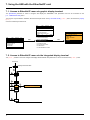
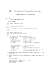
5. 2. Hardware description
LEDs
Shielded female RJ45
EtherNet/IP connector
(Port 2)
5. 3. Installing the card in the drive
See the Installation Manual.
8
MAC address
label
Shielded female RJ45
EtherNet/IP connector
(Port 1)
6. Connecting to the EtherNet/IP network
6. 1. Card RJ45 connector pinout
The EtherNet/IP card is equipped with two shielded RJ45 connectors. The shielding is connected to the drive ground.
Use an STP (shielded twisted pair) EtherNet/IP cable.
Pin
Signal
1
TD+
2
TD-
3
RD+
4
5
6
RD-
7
8........................1
8........................1
8
The transmission speed is detected automatically by the card (10 Mbps or 100 Mbps).
The card can operate in half duplex or full duplex mode, whether connected to a hub or a switch and regardless of the transmission speed
(10 Mbps or 100 Mbps).
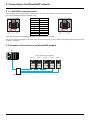
6. 2. Example of connection to an EtherNet/IP network
PLC
Daisy chain and/or star topology
ATV71
ATV71
ATV71
ATV71
ATV71
Ethernet switch
9
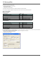
7. Using the HMI with the EtherNet/IP card
7. 1. Access to EtherNet/IP menu via graphic display terminal
The [EtherNet/IP] submenu is used to configure and display the EtherNet/IP card parameters and can be accessed via the
[1.9 - COMMUNICATION] menu.
This menu is only accessible in standard, advanced and expert mode: In the [2 ACCESS LEVEL] (LAC-) menu, set the level to [expert]
(EPr).
Can be accessed by the other level.
RDY
RDY
NET +0.00 Hz
MAIN MENU
1 DRIVE MENU
2 ACCESS LEVEL
3 OPEN / SAVE AS
4 PASSWORD
5 LANGUAGE
Code
0A
ENT
Quick
NET +0.00 Hz
0A
1 DRIVE MENU
1.1 SIMPLY START
1.2 MONITORING
1.3 SETTINGS
1.4 MOTOR CONTROL
1.5 INPUTS/OUTPUTS CFG
Code
<<
>>
Quick
1.6 COMMAND
1.7 APPLICATION FUNCT.
1.8 FAULT MANAGEMENT
1.9 COMMUNICATION
1.10 DIAGNOSTICS
1.11 IDENTIFICATION
1.12 FACTORY SETTINGS
1.13 USER MENU
1.14 PROGRAMMABLE CARD
RUN
ENT
NET
+50.00 Hz 80A
1.9 COMMUNICATION
COM. SCANNER OUTPUT
MODBUS HMI
MODBUS NETWORK
CANopen
EtherNet/IP
Code
<<
>>
Quick
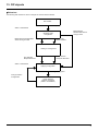
7. 2. Access to EtherNet/IP menu via the integrated display terminal
The (EtH-) submenu is used to configure and display the EtherNet/IP card parameters. It can be accessed via the (COM-) menu.
Power-up
XXX
Displays the drive state
ENT
ESC
SIM-
ESC
FLtENT
ESC
EtH-
CONESC
ESC
FCS-
ESC
LAC-
10
7. Using the HMI with the EtherNet/IP card
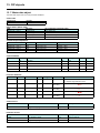
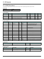
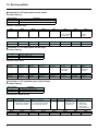
7. 3. Ethernet/IP configuration with the HMI
Detail of the Ethernet/IP configuration menu: (All these settings can also be performed from the webserver or PowerSuite). In the table,
parameters which are not followed by their parameter code (between parenthesis) are not displayed on the 7 segment display of the drive.
[1.9 - COMMUNICATION] (COM-) V menu [ETHIP] (Eth)
Parameter
Possible value
[DEVICE NAME]
16 chars.
The device name is required if the card uses
DHCP to obtain its IP Address.
[Rate Setting] (rdS)
0 : Autodetect (default)
1 : 10 Mbps Full
This field is used to set the transmission
speed and the transmission mode of the 2 : 10 Mbps Half
3 : 100 Mbps Full
card.
4 : 100 Mbps Half (do not use)
[Actual Rate] (Ard)
0 : Autodetect
1 : 10 Mbps Full
This field displays the baud rate and the
2 : 10 Mbps Half
transmission mode currently used by the
3 : 100 Mbps Full
communication card. (Display only)
4 : 100 Mbps Half
[IP mode] (IpM )
0 : Manu
1 : BOOTP
Use this parameter to select the IP address
2 : DHCP
assignment method.
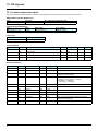
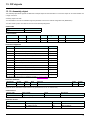
Terminal display
[ABC… ]
[IP card] (IPC-)
These fields are editable when IP mode is set to Fixed
address
(IPC1) (IPC2)
(IPC3) (IPC4)
IP address of the card
[IP Mask] (IPN-)
These fields are editable when IP mode is set to Fixed
address
(IPM1) (IPM2)
(IPM3) (IPM4)
Subnet mask
[IP Gate] (IPG-)
These fields are editable when IP mode is set to Fixed
address
(IPG1) (IPG2)
(IPG3) (IPG4)
Default gateway IP address
• If the address has been given by a BOOTP or a DHCP server, these fields are read only.
• After dynamic addressing by a BOOTP or DHCP server, the new address value is displayed.
[Services] (E E)
0 : Web Server and Email functions are disabled.
Enables web server and e-mail server *
1: Web Server activated.
This parameter is significant at the bit level. 2: Email function activated
3: Web server and Email functions are activated
Bit 0 and bit, other bits are reserved
[139.160.069.241]
(139) (160) (069) (241)
[MAC @]
MAC address display
[00-80-F4-XX-XX-XX]
[00-80-F4-XX-XX-XX]
[Auto] (AUtO)
[10 Mbps full] (10 F)
[10 Mbps half] (10H)
[100 Mbps full] (100F)
[100 Mbps half] (100H)
[Auto] (AUtO)
[10 Mbps full] (10 F)
[10 Mbps half] (10H)
[100 Mbps full] (100F)
[100 Mbps half] (100H)
[fixed] (MAnU)
[BOOTP] (bOOt)
[DHCP] (dHCP)
[255.255.254.0]
(255) (255) (254) (0)
[0.0.0.0]
(0) (0) (0) (0)
0
1
2
3
*: This functionality can only be configured from the WEB server or from PowerSuite commissioning software.
11
7. Using the HMI with the EtherNet/IP card
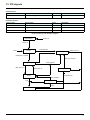
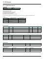
7. 4. Detail of the configured parameters
b IP address
Assigning IP addresses
The drive needs 3 IP addresses:
• The drive IP address.
• The subnet mask.
• The gateway IP address.
They can be provided by:
• A BOOTP server (correspondence between the MAC address and the IP addresses).
• Or a DHCP server (correspondence between Device Name [DEVICE NAME] and the IP addresses).
The address is assigned according to the IPmode parameter:
IP Mode value
IP mode = 0
IP mode = 1
Comments
The card uses the address defined in
IPC1, IPC2, IPC3, IPC4
The card receives its address from a BOOTP server
IP mode = 2
The card receives its address from a DHCP server
And Device name contains a valid name.
IMPORTANT: The IP mode parameter may be modified according to the configuration control attribute of the TCP/IP interface object
(CIP standard). See page 50.
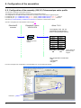
7. 5. Assemblies and scanner configuration
The assemblies are chosen at the master controller level (see for example chapter 16 Integration in RSlogix).
For the 4 ODVA set of assemblies (20,21,22,23,70,71,72,73) there are no more configuration to do at the communication scanner level.
For the Telemecanique assembly (100,101) and Allen Bradley® assembly (103,104) you must:
• configure at the drive level the size of the assembly,
• define the mapping of the additional parameters.
12
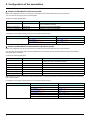
8. Configuration of the assemblies
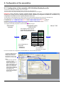
8. 1. Configuration of the assemblies: overview
VW3 A3 316 EtherNet/IP communication card
Features overview
Standard
Web
browser
IE, Mozilla
EtherNet/IP Cyclic exchanges
EtherNet/IP acyclic messages
Master
Controller
IO
Scanner
Assemblies
20 - 70
CIP basic speed control
profile
Assemblies
21 - 71
CIP extended speed control
profile
Assemblies
22 - 72
CIP speed and torque
Control profile
Assemblies
23 - 73
CIP extended speed and torque
Control profile
Assemblies
100 - 101
Telemecanique native drive
Profile
Assemblies
103 - 104
Allen Bradley drive
profile
CIP
Explicit
messaging
Parameters
management
Embedded
Web server
Drive setup
13
8. Configuration of the assemblies
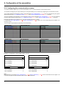
8. 2. Configuration of the assembly (100,101) Telemecanique native profile
The size of the assembly is fixed and is equal to 8.
The mapping of the other parameters is made with the communication scanner :
The configuration of the addresses defined with NCAx and NMAx can be made with the graphic keypad:
For assembly 100 : [1.9- COMMUNICATION] (COM-) menu, [COM.SCANNER OUTPUT] (OCS-) submenu.
For assembly 101 : [1.9- COMMUNICATION] (COM-) menu, [COM.SCANNER INPUT] (ICS-) submenu.
See menu [1.2 MONITORING] > COMMUNICATION MAP to monitor the communication scanner.
See also "Configuring the communication scanner" page 16.
EtherNet/IP
scanner
EtherNet/IP option
VW3 A3 316
Altivar 71/61
The mapping of the 100-101
Assemblies is made with the
ATV71 communication scanner
100-101
Native drive profile
CiA402
NCA1
NCA2
NCA3
NCA4
NCA5
NCA6
NCA7
NCA8
NMA1
NMA2
NMA3
NMA3
NMA4
NMA5
NMA6
NMA7
Assembly
100
Assembly
101
Up to 8 additional
parameters are
mapped.
This configuration is made with:
• HMI
• PowerSuite
• Keypad
Here is an example of the configuration of the assemblies 100, 101 from RSLogix software:
Fixed size !
14
8. Configuration of the assemblies
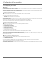
8. 3. Configuration of the assembly (103,104) Allen Bradley® profile
The size of the assembly is selectable from 2 to 10 words.
The 2 first words of the input assembly are fixed: Control word, Speed setpoint.
The 4 first words of the output assembly are fixed two pad words: Status word, Actual Speed.
IMPORTANT: NCA1 and NCA2 are already configured (default settings of the drive). It is important when configuring this
assembly set to handly remove the default assignment of NCA1 and NCA2: By setting NCA1 and NCA2 to a null address or by
configuring this two address to other required parameters of the drive.
This will avoid a conflict between NCA1 and the control word of the profile (located in the first word of the assembly 103).
The configuration of the addresses defined with NCAx and NMAx can be made with the graphic keypad:
For assembly 103 : [1.9- COMMUNICATION] (COM-) menu, [COM.SCANNER OUTPUT] (OCS-) submenu.
For assembly 104 : [1.9- COMMUNICATION] (COM-) menu, [COM.SCANNER INPUT] (ICS-) submenu.
See menu [1.2 MONITORING] > COMMUNICATION MAP to monitor the communication scanner.
See also "Configuring the communication scanner" page 16
The mapping of the other parameters is made with the EtherNet/IP scanner:
EtherNet/IP
scanner
EtherNet/IP option
VW3 A3 316
Altivar 71/61
The mapping of the 103-104
Assemblies is made with the
option card EtherNet/IP scanner
103-104
Native drive profile
CiA402
This configuration is
made with:
• Webserver
• PowerSuite
PAD WORD
PAD WORD
Control Word Status Word
Set point
Actual speed
NCA1
NMA1
NCA2
NMA2
NCA3
NMA3
NCA4
NMA3
NCA5
NMA4
NCA6
NMA5
NCA7
NMA6
NCA8
NMA7
Assembly
103
Assembly
104
Up to 8 additional
parameters are mapped.
Here is an example of the configuration of the assemblies 103, 104 from RSLogix software
The sizes indicated must be
adjusted according to the
settings defined with the
EtherNet/IP scanner setup
(webserver or Power suite).
Note:
• The size of the assembly
cannot be modified
dynamically; such change
requires a power ON.
• Given that assemblies 103
and 104 uses NCAx and
NMAx, the configuration
edited with the webserver
or Power suite software are
also applied to the
communication scanner of
the drive (like assemblies
100 and 101).
15
8. Configuration of the assemblies
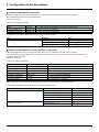
8. 4. Configuring the communication scanner
You need to read this chapter only if you use the assemblies 100 or 101 that use the drive communication scanner.
The variables exchanged by the output assembly 100 and input assembly 101 are selected by configuring the communication scanner.
The 8 output variables are assigned by means of the 8 parameters [Scan. Outp address] (nCAp). They are configured using the graphic
display terminal via the [1.9 - COMMUNICATION] (COM-) menu, [COM. SCANNER OUTPUT] (OCS-) submenu.
The 8 input variables of the assembly 101 are assigned by means of the 8 parameters [Scan. Inp address] (nMAp). They are configured
using the graphic display terminal via the [1.9 - COMMUNICATION] (COM-) menu, [COM. SCANNER INPUT] (ICS-) submenu.
Enter the logic address of the parameter (see the Communication parameters manual).
If a parameter [Scan. Outp address] (nCAp) or [Scan. Inp address] (nMAp) is equal to zero, the corresponding period variable is not
used by the drive.
These 8 assignment parameters are described in the tables below:
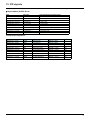
Parameter name
Output assembly 100
Default assignment
[Scan. Out1 address] (nCA1)
NCA1 = 8501
[Scan. Out2 address] (nCA2)
NCA2 = 8602
[Scan. Out3 address] (nCA3)
NCA3 = not used
[Scan. Out4 address] (nCA4)
NCA4 = not used
[Scan. Out5 address] (nCA5)
NCA5 = not used
[Scan. Out6 address] (nCA6)
NCA6 = not used
[Scan. Out7 address] (nCA7)
NCA7 = not used
[Scan. Out8 address] (nCA8)
NCA8 = not used
Parameter name
Input assembly 101
Default assignment
[Scan. In1 address] (nMA1)
NMA1=3201
[Scan. In2 address] (nMA2)
NMA2=8604
[Scan. In3 address] (nMA3)
NMA3=not used
[Scan. In4 address] (nMA4)
NMA4=not used
[Scan. In4 address] (nMA5)
NMA5=not used
[Scan. In4 address] (nMA6)
NMA6=not used
[Scan. In4 address] (nMA7)
NMA7=not used
[Scan. In4 address] (nMA8)
NMA8=not used
Example of configuration via the graphic display terminal:
RDY
NET
+0.00Hz
0A
RDY
COM. SCANNER INPUT
NET
+0.00Hz
0A
COM. SCANNER OUTPUT
Scan. In1 address
:
3204
Scan. Out1 address
:
9001
Scan. In2 address
:
3206
Scan. Out2 address
:
9002
Scan. In3 address
:
0
Scan. Out3 address
:
0
Scan. In4 address
:
0
Scan. Out4 address
:
0
Scan. In5 address
:
0
Scan. Out5 address
:
0
Code
Quick
Code
Quick
Scan. In6 address
:
0
Scan. Out6 address
:
0
Scan. In7 address
:
0
Scan. Out7 address
:
0
Scan. In8 address
:
0
Scan. Out8 address
:
0
Note:
All modifications to parameters [Scan. Outp address] (nCAp) or [Scan. Inp address] (nMAp) must be made with the motor stopped. The
master PLC program should be updated to take account of this modification.
16
8. Configuration of the assemblies
8. 5. Configuring the control
b Principle
By the configuration of the control, it is possible to decide from what channel the drive receives its commands and setpoint, either
permanently or depending on a switching command.
Numerous configurations are possible. For more information, refer to the Programming manual and Communication parameters manual.
The following configurations are some of the possibilities available.
M Control with communication scanner
If the default assemblies (100, 101) are selected, all possibilities of Altivar 71 drive are available.
It is possible to use all profiles and modes of the drive:
- I/O profile,
- Drivecom profiles with separate or non separate mode.
By the configuration of the communication scanner, it is possible to assign any relevant parameter of the drive to the 4 input and 4 output
variables of the assemblies.
See the input / output interface with the PLC can be fully customised depending on the application.
The use of the communication scanner is also the best way to interface with a "Controller Inside" card.
M Control according to ODVA AC drive profile
The ODVA AC drive profile is activated when one of the following assemblies is selected:
• 20: Basic speed control output
• 21: Extended speed control output
• 22: Speed and torque control output
• 23: Extended speed and torque control output
• 70: Basic speed control input
• 71: Extended speed control input
• 72: Speed and torque control input
• 73: Extended speed and torque control input
The advantage of using the ODVA drive profile standard is the interchangeability with other brands.
The drive must be configured in the Drivecom profile with separate mode.
The EtherNet/IP card translates the commands, behaviour and monitoring information from of ODVA profile (on the network) to the
Drivecom profile (in the drive).
M Control according to Allen-Bradley® drive profile
The Allen-Bradley® Drive profile is activated when one of the following assemblies is selected:
• 103: Allen-Bradley® drive output
• 104: Allen-Bradley® drive input
If you need to replace Allen-Bradley® drives, in an existing application, this profile is a good way to minimise the modifications.
The drive must be configured in the Drivecom profile with separate mode.
The EtherNet/IP card translates the commands, behaviour and monitoring information from of Allen-Bradley® drive profile (on the network)
to the Drivecom profile (in the drive).
17
8. Configuration of the assemblies
b Available configurations
M If you use the communication scanner:
• 100: Communication scanner output
• 101: Communication scanner input there is no limitation in the configuration of the control.
The examples below are only possible if you use the communication scanner.
M If you use the ODVA AC drive profile or Allen-Bradley® Drive profile, that is, the assemblies:
•
•
•
•
•
•
•
•
•
•
20: Basic speed control output
21: Extended speed control output
22: Speed and torque control output
23: Extended speed and torque control output
70: Basic speed control input
71: Extended speed control input
72: Speed and torque control input
73: Extended speed and torque control input
103: Allen-Bradley® drive output
104: Allen-Bradley® drive input
Parameter
Profile
Permitted value
Drivecom profile separate
Setpoint 1 configuration
Setpoint 1B configuration
Setpoint 2 configuration
Command 1 configuration
Command 2 configuration
Setpoint switching
Command switching
Network card
Terminals
Terminals
Network card
Terminals
Network card bit 12
Network card bit 13
Comment
The run commands are in Drivecom profile,
the command and the reference can come from different channels.
Setpoint 1 comes from EtherNet/IP.
Setpoint 2 comes from terminals (AI1 or AI2).
Setpoint 2 comes from terminals (AI1 or AI2).
Command 1 comes from EtherNet/IP.
Command 2 comes from terminals.
Bit 12 of the control word switches the setpoint (1 <-> 1B or 1 <-> 2).
Bit 13 of the control word switches the command.
Configuration via the graphic display terminal or the integrated display terminal:
Case 1: Setpoint 1B is connected to the functions (Summing, PID, etc) which remain active even after switching.
Menu
Parameter
Permitted value
[1.6 - COMMAND] (CtL-)
[Profile] (CHCF)
[Separate] (SEP)
[Ref.1 channel] (Fr1)
[Com. card] (nEt)
[Ref.1B channel] (Fr1b)
[Ref. AI1] (AI1) or [Ref. AI2] (AI2)
[Cmd channel 1] (Cd1)
[Com. card] (nEt)
[Cmd channel 2] (Cd2)
[Terminals] (tEr)
[Cmd switching] (CCS)
[C312] (C312)
[1.7 APPLICATION FUNCT.] (FUn-)
[Ref 1B switching] (rCb)
[C313] (C313)
[REFERENCE SWITCH.]
Case 2: Setpoint 2 is directly connected to the drive reference limit. If switching is performed, the functions that affect the reference
(summing, PID, etc.) are inhibited.
Menu
Parameter
Permitted value
[1.6 - COMMAND] (CtL-)
[Profile] (CHCF)
[Separate] (SEP)
[1.7 APPLICATION FUNCT.] (FUn-)
[Ref.1 channel] (Fr1)
[Com. card] (nEt)
[REFERENCE SWITCH.]
[Ref.2 channel] (Fr2)
[Ref. AI1] (AI1) or [Ref. AI2] (AI2)
[Cmd channel 1] (Cd1)
[Com. card] (nEt)
[Cmd channel 2] (Cd2)
[Terminals] (tEr)
[Cmd switching] (CCS)
[C312] (C312)
[Ref. 2 switching] (rFC)
[C313] (C313)
Note: It is not possible to configure the display terminal as a channel.
To switch to the display terminal, use the function force local and assign the parameter [Forced local Ref.] to [HMI] (LCC).
18
8. Configuration of the assemblies
b Control via EtherNet/IP in I/O profile
Note: This configuration can only be used if the communication scanner assemblies (100 and 101) are selected.
The command and the setpoint come from EtherNet/IP.
Control is in I/O profile.
Configure the following parameters:
Parameter
Value
Comment
Profile
I/O profile
The run command is simply obtained by bit 0 of the command word.
Setpoint 1 configuration
Network card The setpoint comes from EtherNet/IP.
Command 1 configuration
Network card The command comes from EtherNet/IP.
Configuration via the graphic display terminal or the integrated display terminal:
Menu
Parameter
Value
[1.6 - COMMAND] (CtL-)
[Profile] (CHCF)
[I/O profile] (IO)
[Ref.1 channel] (Fr1)
[Com. card] (nEt)
[Cmd channel 1] (Cd1)
[Com. opt card] (nEt)
b Control via EtherNet/IP or via the terminals in I/O profile
Note: This configuration can only be used if the communication scanner assemblies (100 and 101) are selected.
The command and the setpoint both come from EtherNet/IP or the terminals. Input LI5 at the terminals is used to switch between
EtherNet/IP and the terminals.
Control is in I/O profile.
Configure the following parameters:
Parameter
Value
Comment
Profile
I/O profile
The run command is simply obtained by bit 0 of the control word.
Setpoint 1 configuration
Network card
Setpoint 1 comes from EtherNet/IP.
Setpoint 1B configuration
Analog input 1 on the terminals Setpoint 1B comes from input AI1 on the terminals.
Setpoint switching
Input LI5
Input LI5 switches the setpoint (1 ↔1B).
Command 1 configuration
Network card
Command 1 comes from EtherNet/IP.
Command 2 configuration
Terminals
Command 2 comes from the terminals.
Command switching
Input LI5
Input LI5 switches the command.
Note: Setpoint 1B is connected to the functions (Summing, PID, etc) which remain active even after switching.
Configuration via the graphic display terminal or the integrated display terminal:
Menu
Parameter
Value
[1.6 - COMMAND] (CtL-)
[Profile] (CHCF)
[I/O profile] (IO)
[Ref.1 chan] (Fr1)
[Com. card] (nEt)
[Cmd channel 1] (Cd1)
[Com. card] (nEt)
[Cmd channel 2] (Cd2)
[Terminals] (tEr)
[Cmd switching] (CCS)
[LI5] (LI5)
[Ref.1B chan] (Fr1b)
[AI1 ref.] (AI1)
[Ref 1B switching] (rCb)
[LI5] (LI5)
[1.7 APPLICATION FUNCT.] (FUn-)
[REFERENCE SWITCH.]
19
8. Configuration of the assemblies
b Control via EtherNet/IP in Drivecom profile
Note: This configuration can only be used if the communication scanner assemblies (100 and 101) are selected.
The command and the setpoint come from EtherNet/IP.
Configure the following parameters:
Parameter
Value
Comment
Profile
Separate Drivecom profile
The run commands are in Drivecom profile, the command and the setpoint can
come from different channels.
Setpoint 1 configuration
Network card
The setpoint comes from EtherNet/IP.
Command 1 configuration
Network card
Command 1 comes from EtherNet/IP.
Configuration via the graphic display terminal or the integrated display terminal:
Menu
Parameter
Value
[1.6 - COMMAND] (CtL-)
[Profile] (CHCF)
[Separate] (SEP)
[Ref.1 chan] (Fr1)
[Com. card] (nEt)
[Cmd channel 1] (Cd1)
[Com. card] (nEt)
b Control via EtherNet/IP or the terminals in Drivecom profile
Note: This configuration can only be used if the communication scanner assemblies (100 and 101) are selected.
The command and the setpoint both come from EtherNet/IP or the terminals. Input LI5 at the terminals is used to switch between
EtherNet/IP and the terminals.
Configure the following parameters:
Parameter
Value
Comment
Profile
Separate Drivecom profile
The run commands are in Drivecom profile, the command and the
setpoint can come from different channels.
Setpoint 1 configuration
Network card
Setpoint 1 comes from EtherNet/IP.
Setpoint 2 configuration
Analog input 1 on the terminals
Setpoint 2 comes from input AI1 on the terminals.
Setpoint switching
Input LI5
Input LI5 switches the setpoint (1 ↔ 2) and the command.
Command 1 configuration
Network card
Command 1 comes from EtherNet/IP.
Command 2 configuration
Terminals
Command 2 comes from the terminals.
Command switching
Input LI5
Input LI5 switches the command.
Note: Setpoint 2 is directly connected to the drive reference limit. If switching is performed, the functions that affect the reference (summing,
PID, etc) are inhibited.
Configuration via the graphic display terminal or the integrated display terminal:
Menu
Parameter
Value
[1.6 - COMMAND] (CtL-)
[Profile] (CHCF)
[Separate] (SEP)
[Ref.1 chan] (Fr1)
[Com. card] (nEt)
[Ref.2 chan] (Fr2)
[AI1 ref.] (AI1)
[Ref. 2 switching] (rFC)
[LI5] (LI5)
[Cmd channel 1] (Cd1)
[Com. card] (nEt)
[Cmd channel 2] (Cd2)
[Terminals] (tEr)
[Cmd switching] (CCS)
[LI5] (LI5)
20
8. Configuration of the assemblies
b Control in Drivecom profile via EtherNet/IP and setpoint switching at the terminals
Note: This configuration can only be used if the communication scanner assemblies (100 and 101) are selected.
The command comes from EtherNet/IP.
The setpoint comes either from EtherNet/IP or from the terminals. Input LI5 at the terminals is used to switch the setpoint between EtherNet/
IP and the terminals.
Control is in Drivecom profile.
Configure the following parameters:
Parameter
Value
Comment
Profile
Separate Drivecom profile
The run commands are in Drivecom profile, the command and the
setpoint can come from different channels.
Setpoint 1 configuration
Network card
Setpoint 1 comes from EtherNet/IP.
Setpoint 1B configuration
Analog input 1 on the terminals
Setpoint 1B comes from input AI1 on the terminals.
Setpoint switching
Input LI5
Input LI5 switches the setpoint (1 ↔1B).
Command 1 configuration
Network card
Command 1 comes from EtherNet/IP.
Command switching
Channel 1
Channel 1 is the command channel.
Note: Setpoint 1B is connected to the functions (summing, PID, etc) that remain active, even after switching.
Configuration via the graphic display terminal or the integrated display terminal:
Menu
Parameter
Value
[1.6 - COMMAND] (CtL-)
[Profile] (CHCF)
[Separate] (SEP)
[Ref.1 chan] (Fr1)
[Com. card] (nEt)
[Cmd channel 1] (Cd1)
[Com. card] (nEt)
[Cmd switching] (CCS)
[ch1 active] (Cd1)
[Ref.1B chan] (Fr1b)
[AI1 ref.] (AI1)
[Ref 1B switching] (rCb)
[LI5] (LI5)
[1.7 APPLICATION FUNCT.] (FUn-)
[REFERENCE SWITCH.]
21
9. Fault management
9. 1. Fault management
An EtherNet/IP time out is triggered if the card does not receive any cyclic messages (regardless within a predefined time period).
This period is managed by the EtherNet/IP controller (not by the drive) and is configured in its module properties box. The duration of the
time out is defined by the RPI (Request packet intervals).
If the card is controlled by explicit messages(without periodic exchanges) There is no control of the communication time-out.
The response of the drive in case of such event can be configured.
RDY
Configuration can be performed using the graphic display terminal or
integrated display terminal using the [Network fault mgt] (CLL)
parameter in the [1.8 FAULT MANAGEMENT] (FLt-) menu, [COM.
FAULT MANAGEMENT] (CLL-) submenu.
NET
+0.00Hz
0A
COM. FAULT MANAGEMENT
Network fault mgt
:
Freewheel
CANopen fault mgt
:
Freewheel
Modbus fault mgt
:
Freewheel
:
:
Code
Quick
The values of the [Network fault mgt] (CLL) parameter, trigger a [COM. network] (CnF) drive fault, are:
Value
[Freewheel] (YES)
[Ramp stop] (rMP)
[Fast stop] (FSt)
[DC injection] (dCI)
Meaning
Freewheel stop (factory setting)
Stop on ramp
Fast stop
DC injection stop
The values of the [Network fault mgt] (CLL) parameter, which do not trigger a drive fault, are:
Value
[Ignore] (nO)
[Per STT] (Stt)
[Fallback spd] (LFF)
[Spd maint.] (rLS)
Meaning
Fault ignored
Stop according to configuration of [Type of stop] (Stt)
Switch to fallback speed, maintained as long as the fault is present and the run command is
not disabled.
The drive maintains the speed at the time the fault occurred, as the fault persists and the
run command has not been removed.
The fallback speed can be configured via the [Fallback spd] (LFF) parameter in the [1.8 FAULT MANAGEMENT] (FLt-) menu.
22
9. Fault management
9. 2. Status of the LEDs
The VW3 A3 316 Ethernet/IP card features 5 LEDs, which are visible through the Altivar 61/71 cover.
1.1
1.2
1.3
1.4
1.5
2.1
2.2
2.3
2.4
2.5
Port 1 activity
Port 2 activity
Link status
NS "Network status"
MS "Module status"
The 2 first LEDS are respectively dedicated to each Ethernet port.
The third LED is relative to the IP level.
The 2 last LEDs are specific to EtherNet/IP and CIP communication protocol.
LED
2.1
Color/ state
Off
Flashing Green/yellow
Green ON
Yellow ON
Green BLINK
Yellow BLINK
Description
No link
Power up testing.
Link at 100 Mbps.
Link at 10 Mbps.
Activity at 100 Mbps.
Activity at 10 Mbps.
2.2
Off
Flashing Green/yellow
Green ON
Yellow ON
Green BLINK
Yellow BLINK
No link
Power up testing.
Link at 100 Mbps.
Link at 10 Mbps.
Activity at 100 Mbps.
Activity at 10 Mbps.
2.3
Off
Flashing Green/red
Green ON
Green flashing 3 times
Green flashing 4 times
Green flashing 5 times
Physical connections unplugged - No IP address obtained
Power up testing.
At least one port is connected and an IP address has been obtained.
All ports are unplugged, but the card has an IP address.
Error: Duplicated IP address (1)
The card is performing a BOOTP or DHCP sequence
2.4
"NS"
Off
Flashing Green/red
Green ON
Green flashing
Red flashing
Red ON
The device does not have an IP address or powered off.
Power up testing.
The device has at least one established connection (even to the Message Router).
The device has not established connections, burt has obtained an IP address.
One or more of the connections in which this device is the target has timed out. This shall be left only if
all time out connections are reestablished or if the device is reset.
The device has detected that its IP address is already in use (1).
Off
Flashing Green/red
Green ON
Green flashing
Red flashing
Red ON
No power is supplied to the device
Power Up testing.
The device is operating correctly.
The device has not been configured.
The device has detected a recoverable minor fault.
The device has detected a non-recoverable major fault (1).
2.5
"MS"
(1) In case of duplicate IP Address, the led 2.3 is green flashing 4 times, led 2.4 and 2.5 are solid red.
23
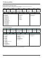
10. Configuration of monitored parameters
It is possible to select up to 4 parameters to display their values in the [1.2 - MONITORING] menu on the graphic display terminal.
The selection is made via the [6 - MONITORING CONFIG.] menu, [6.3 - COM. MAP CONFIG.] submenu.
Each parameter in the range [Address 1 select.] … [Address 4 select.]
is used to select the parameter logic address. Select an address of zero
to disable the function.
In the example given here, the monitored words are:
• Parameter 1 = Motor current (LCR): logic address 3204;
signed decimal format.
• Parameter 2 = Motor torque (OTR): logic address 3205;
signed decimal format.
• Parameter 3 = Last fault occurred (LFT): logic address 7121;
hexadecimal format.
• Disabled parameter: address 0; default format: hexadecimal format.
RDY
NET
+0.00Hz
0A
6.3 COM. MAP CONFIG.
Word 1 add. select.
:
3204
Format word 1
:
Signed
Word 2 add. select.
:
3205
Format word 2
:
Signed
Word 3 add. select.
:
7121
Code
Quick
Format word 33
:
Hex
Word 4 add. select.
Format word 4
:
:
One of the three display formats below can be assigned to each monitored word:
Format
Hexadecimal
Signed decimal
Unsigned decimal
24
Range
0000 … FFFF
-32,767 … 32,767
0 … 65,535
Terminal display
[Hex]
[Signed]
[Unsigned]
0
Hex
11. Webserver
This chapter describes the function of the integrated webserver of the EtherNet/IP card.
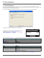
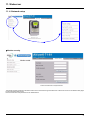
11. 1. Opening the Altivar home page
From your web browser, default http password and login are : USER, USER for monitor and setup security level and ADMIN, ADMIN for
administrator level.
From the altivar home page, you can access to 4 main menus:
• Drive,
• Network setup,
• Network diagnostic,
• Email
11. 2. Web pages structure
Each web page uses the same structure. Each main menu, "Drive", "Network setup" and "Network Diagnostics" contains each own sub
menu. This last one is displayed on the left side of web page.
The
toggle button shows or hides the left sided menu.
25
11. Webserver
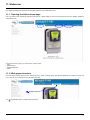
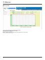
11. 3. Drive
b Drive monitor
26
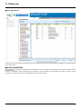
11. Webserver
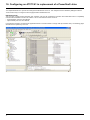
b Drive parameters
The left column is used to select a mod/imd group (or list) of parameters. The right columns displays the parameters, its Modbus address
and its current value.
bSAVING PARAMETERS
When parameters of the drive are modified from the webserver, they are not saved into drive memory (to avoid numerous write access to
the flash memory).
However, it is possible to perform the backup of the parameters from the webserver: This operation can be done by writing 2 to CMI
parameter. This operation saves ALL the parameters of the drive to flash memory.
27
11. Webserver
b Drive recorder
The trend viewer shows traces of two preselected parameters
RUN/STOP: Starts or stoppes the trends recording.
Reset : Erases the recorded trend.
Min/Max : defines the lowest and highest values that are displayed on the trend window.
Per(s) : Periodicity : Minimal value.
28
11. Webserver
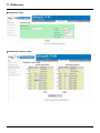
11. 4. Network setup
b Monitor security
The Monitor security password is the basic level access to the drive through the webserver: it allows the access to the different web pages
but don’t authorize write access.
New level username and password can be redefined here.
29
11. Webserver
b Setup security
- HTTP : data write.
- Data write level password.
b Administrator security
30
11. Webserver
b EtherNet/IP setup
b EtherNet/IP scanner setup
31
11. Webserver
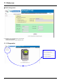
b Email management
Configuration of the email generator on the left side:
- email IP server Address
- email sender address, recipient address from θ.
11. 5. Diagnostics
32
11. Webserver
b Ethernet statistics
b Message statistics
NOTE: As a Schneider product, The EtherNet/IP option card uses internally MODBUS TCP for the web-server. (The MODBUS TCP port
is not accessible).
33
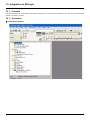
12. Integration in RSLogix
12. 1. Principle
RSX drive equipped with an EtherNet/IP card shall be configured as a "Generic Ethernet Module" in the same way as the EtherNet/IP
adapter of PowerFlex 70 drives.
12. 2. Procedure
b Create a new project
34
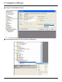
12. Integration in RSLogix
b Add a EtherNet/IP scanner to the I/O configuration
35
12. Integration in RSLogix
36
12. Integration in RSLogix
b Configure the EtherNet/IP scanner
b Add a EtherNet/IP ATV71/61 drive to the I/O configuration
37
12. Integration in RSLogix
38
12. Integration in RSLogix
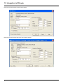
b Configure the ATV71 EtherNet/IP card
Above the Allen-Bradley drive profile is selected.
39
12. Integration in RSLogix
Below the CIP extended speed control profile is selected.
Below the CIP extended speed and torque control profile is selected.
40
12. Integration in RSLogix
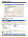
Below native RSX profile is selected.
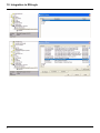
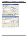
12. 3. Registering the EDS file in RSlogix
An EDS file is provided with the drive. (This file is available on the CD or on www.telemecanique.com).
It exists 1 EDS file for the ATV71 and 1 EDS file for the ATV61.
The following lines describe how to import these files in your project:
In RSnetWorx , start the EDS wizards
41
12. Integration in RSLogix
Follow the instructions:
Choose "Register" to import a new EDS file.
If you want to update an EDS file you need to "unregister" this device first.
42
12. Integration in RSLogix
Select the required file:
Then finish, the dialog box displays the result of the import operation.
43
13. CIP objects
13. 1. Supported object classes
Three categories of object classes can be defined:
• 1: CIP device on EtherNet/IP.
• 2: AC/DC drive.
• 3: VSD specific.
These objects are detailed here:
16#01
16#02
16#F6
16#F5
16#05
1
1
1
1
1
Number of
instances
1
1
1
1
1
16#28
16#29
2
2
1
1
Defines data for the motor connected to the device
Manages drive functions, operational states and control
16#2A
16#04
2
2
3
1
12
1
Provides drive configuration
Defines I/O data format
Vendor specific - drive's parameters
Object class
Class ID
Identity object (13. 2.) page 44
Message router object (13. 3.) page 45
Ethernet Link object (13. 4.) page 47
TCP/IP Interface object (13. 5.) page 50
Connection object manager (13. 6.)
page 52
Motor data object (13. 7.) page 53
Control supervisor object (13. 8.) page
54
AC/DC Drive Object (13. 9.) page 56
Assembly object (13. 10.) page 57
Application objects (13. 11.) page 58
Cat.
Effect on behavior Interface
Supports the reset service
Explicit message connection
Counter and status information
TCP/IP configuration
13. 2. Identity object
The Identity object provides identification and status information about the drive.
Class code
Hexadecimal
16#01
Decimal
1
Class attributes
Attribute ID
Access
Name
Need
Data type
Value
Details
1
Get
Revision
Opt.
UINT
1
—
2
Get
Max Instances
Opt.
UINT
1
1 defined instance
44
13. CIP objects
Instance attributes
Attribute ID
Access Name
Need Data type
Value
Details
1
Get
Vendor ID
Req.
UINT
243
Schneider Automation, Inc [243]
2
Get
Device type
Req.
UINT
16#02 AC/DC drive profile
3
Get
Product code
Req.
UINT
5 or 7
5: ATV71
7: ATV61
4
Get
Revision
Req.
Struct of:
USINT
USINT
—
Product revision of the drive (1)
5
Get
Status
Req.
WORD
—
See definition in the table below
6
Get
Serial number
Req.
UDINT
—
Serial number of the drive
7
Get
Product name
Req.
Struct of:
USINT
STRING
—
11 (product name length)
“ATV71 Drive”
8
Get
State
Opt.
USINT
—
0: Non existent
1: Device self-testing
2: Standby
3: Operational
4: Major recoverable fault
5: Major unrecoverable fault
10
Get/Set
Heartbeat interval (2)
Opt.
USINT
0–255 Interval in seconds between two heartbeat messages.
0: No message.
(1) Mapped in a word: MSB minor revision (second USINT), LSB major revision (first USINT).
Example: 517 = 16#0205 means revision V5.2.
(2) The heartbeat message broadcasts the current state of the device.
13. 3. Message router object
The Message router object is the element through which all the "Explicit messages" objects pass in order to be directed towards the objects
they are truly destined to.
Class code
Hexadecimal
16#02
Decimal
2
Class attributes
Attribute ID
Access
Name
Need
Data type
Value
Details
1
Get
Revision
Opt.
UINT
1
-
2
Get
Max instances
Opt.
UNT
1
1 Defined instance
45
13. CIP objects
Instance attributes
Attribute ID
Access Name
Need Data type
Value
Details
1
Get
Object list:
Number classes
Opt.
Struct of:
UINT
UINT [ ]
20
(codes)
List of supported objects; the first UINT is the number of
supported classes; the remaining UINTs are the codes of
these classes.
2
Get
Number available
Opt.
UINT
1
Maximum number of simultaneous connections
3
Get
Number active
Opt.
UINT
1
Number of active connections
4
Get
Active connections Opt.
UINT [ ]
1
List of active connections (referred to with their respective
Connection instance ID)
Class service
Service code
Service name
Need
Description
16#0E
Get_Attribute_Single
Req.
Read an attribute
Service code
Service name
Need
Description
16#0E
Get_Attribute_Single
Req.
Read an attribute
Instance service
46
13. CIP objects
13. 4. Ethernet Link object
This object provides the mechanism to configure a device's TCP/IP network interface.
b Class code
Hexadecimal
16#F5
decimal
245
b Class attributes
Class attributes for this object are optional.
b Instance attributes
Attribute ID
1
Access
Get
Name
Status
need
Req.
Data type
DWORD
Value
Bit level
2
Get
Configuration
capability
Req.
DWORD
Details
The interface configuration attribute has not
been configured.
1 The interface configuration contains a valid
configuration.
2-15 Reserved for future use.
0
BOOTP Client.
0
1 DNS Client.
Bit level
2 DHCP Client.
3 DHCP-DNS capable.
4 Interface configuration settable.
All other bits are reserved and shall be set to 0.
3
Get
Configuration
Req.
DWORD
0 The interface configuration is valid.
Set
control
The interface configuration must be
1
obtained with BOOTP.
The interface configuration must be
2
Bit level
obtained with DHCP..
3 Reserved.
NOTE : This attribute interacts with the Altivar 71 parameter [IPmode].
4 DNS Enable.
(see chapter 8. ).
All other bits are reserved and shall be set to 0.
4
Get
Physical link
Req.
STRUCT {
Path size: number of 16 bit words in the element
UINT path size
Path
Padded EPATH path
Path: Logical segments identifying the physical
}
link object. The path is restricted to one logical
class segment and one logical instance segment.
The maximum size is 12 bytes.
47
13. CIP objects
Attribute ID
5
Access
Get
Set
Name
Interface
configuration
need
Req.
Data type
STRUCT {
Value
UDINT IP Address
Details
IP Address: Value of 0 indicates noIP address has
been configured. Otherwise, the IP address shall be
set to a valid Class A, B, or C address and shall not
be set to the loopback address (127.0.0.1).
UDINT Network Mask
Network Mask: Value of 0 indicates no network
UDINT Gateway address mask address has been configured.
UDINT Primary Name
server
Gateway Address: Value of 0 indicates no IP
address has been configured. Otherwise, the IP
address shall be set to a valid Class A, B, or C
UDINT Secondary name address and shall not be set to the loopback
server
address (127.0.0.1).
STRING Default Domain Primary name: Value of 0 indicates no name
name
server address has been configured. Otherwise, the
name server address shall be set to a valid Class A,
}
B, or C address.
Secondary Name: Value of 0 indicates no
secondary name server address has been
configured. Otherwise, the name server address
shall be set to a valid Class A, B, or C address.
6
Get
Set
Host Name
Req.
Default domain name: ASCII characters.
Maximum length is 48 characters. Shall be padded
to an even number of characters (pad not included
in length). A length of 0 shall indicate no Domain
Name is configured.
ASCII characters. Maximum length is
64 characters. Shall be padded to an even number
of characters (pad not included in length). A length
of 0 shall indicate no Host Name is configured.
STRING
b Class service
Service Code
16#01
Service Name
Get_Attribute_All
Need
Optional
16#0E
Get_Attribute_Single
Optional
Service Code
16#01
Service Name
Get_Attribute_All
Need
Optional
16#0E
16#02
16#10
Get_Attribute_Single
Set_Attribute_All
Set_Attribute_Single
Required
optional
Required
Description
Returns a predefined listing of this objects
attributes.
Returns the contents of the specified attribute.
b Instance service
48
Description
Returns a predefined listing of this objects
attributes.
Returns the contents of the specified attribute.
Modifies all settable attributes.
Modifies a single attribute.
13. CIP objects
b Behaviour
The following state machine is used to configure the TCP/IP network interface.
Non-existent
Powerup/Reset
Status = 0x00000000
BOOTP/DHCP
Disabled AND Stored
Config is Valid
Obtaining initial
Configuration
BOOTP OR
DHCP Enabled
BOOTP/DHCP Disabled AND
Stored Config is Invalid
Waiting for Configuration
BOOTP/DHCP
Response Received
Set_Attributes
Request Received
Status = 0x00000000
Applying Configuration
Configuration Applied
Change Interface
Configuration
TCP/IP Network
Interface Configured
(Status = 0x00000001)
49
13. CIP objects
13. 5. TCP/IP Interface object
This object maintains link specific counters and status information for an Ethernet 802.3 communications interface.
b Class code
Hexadecimal
16#F6
Decimal
246
b Class attributes
Attribute ID
1
2 through 7
Access
Get
Name
Revision
Need
Req.
optional
Data type
UINT
Value
2
b Instance attributes ../
Attribute ID
1
Access
Get
Name
Need
Interface Speed Req.
Data type
UDINT
Value
Details
0,10,100 Speed in Mbps.
1000, etc.
0
Link status
1
Half/full duplex
2-4 Negotiation status
Bit
level
5
Manual setting / requires reset
6
Local Hardware fault
All other bits are reserved and shall be set to 0.
This array contains the MAC address of the
card.Format: XX-XX-XX-XX-XX-XX
2
Get
Interface flags
Req.
DWORD
3
Get
Physical
Address
Req.
ARRAY OF
6 USINTs
4…
Get
Interface
counters
Cond.
STRUCT {
UDINT In Octets
UDINT In Ucast Packets
UDINT In NUcast
Packets
UDINT In Discards
UDINT In Errors
UDINT In Unknown
Protos
UDINT Out Octets
UDINT Out Ucast
packest
UDINT Out NUcast
Packets
UDINT Out discards
UDINT
}
50
Octets received on the interface
Unicast Packets received on the interface.
Non Unicast Packets received on the interface.
Inbound packets received on the interface but
discarded.
Inbound packets that contain errors. (does not
include in Discards)
Inbound packets with unknown protocol.
Octets sent on the interface.
Unicast Packets sent on the interface.
Non Unicast Packets sent on the interface.
Outbound packets discarded
Outbound packets that contain errors
13. CIP objects
Attribute ID
5
Access
Get
Name
Need
Media Counters Cond.
6
Set
Interface control Optional
Data type
Value Details
STRUCT {
UDINT Alignment errors
Frames received that are not an integral
number of octets in length
UDINT FCS Errors
Frames received that do not pass the FCS
check
UDINT Single collisions
Successfully transmitted frames which
experienced exactly one collision
UDINT Multiple Collisions
Successfully transmitted frames which
experienced more than one collision
UDINT SQE Test Errors
Number of times SQE test error message is
generated
UDINT Deferred
Frames for which first transmission attempt
Transmissions
is delayed because the medium is busy
UDINT Late Collisions
Number of times a collision is detected later
than 512 bittimes into the transmission of a
packet
UDINT Excessive Collisions
Frames for which transmission fails due to
excessive collision
UDINT MAC Transmit errors
Frames for which transmission fails due to
an internal MAC sublayer transmit error
UDINT Carrier sense Errors
Times that the carrier sense condition was
lost or never asserted when attempting to
transmit a frame
UDINT Frame too long
Frames received that exceed the maximum
permitted frame size
UDINT MAC Receive Errors
Frames for which reception on an interface
fails due to an internal MAC sublayer
receive error
}
STRUCT {
WORD Control Bits
Interface control bits
UINT Force interface
Speed at which the interface shall be forced
Speed
to operate.
}
51
13. CIP objects
b Class service
Service Code
16#01
16#0E
16#10
Service Name
Get_Attribute_All
Get_Attribute_Single
Get_and_clear
Need
Optional
Optional
Cond.
Description
Returns a predefined listing of this objects attributes.
Returns the contents of the specified attribute.
Modifies a single attribute
Service Name
Get_Attribute_All
Get_Attribute_Single
Set_Attribute_Single
Need
Optional
Required
Required
Description
Returns a predefined listing of this objects attributes.
Returns the contents of the specified attribute.
Modifies a single attribute.
b Instance service
Service Code
16#01
16#0E
16#10
13. 6. Connection object manager
Class code
Hexadecimal
16#05
Decimal
5
Class attributes
Attribute ID
Access
Name
Need
Data type
Value
Details
1
Get
Revision
Opt.
UINT
1
—
2
Get
Max instances
Opt.
UINT
4
3 defined instances (1)
(1) Only instances 1 (explicit message), 2 (polled I/O message), and 4 (change of state/cyclic message) are supported. Instance 3 (bit
strobe) is not supported.
Attributes of instance 1—Explicit message instance
Attribute ID
Access
Name
Need
Data type
Value
Details
1
Get
State
Req.
USINT
—
0 : Non-existent
3 : Established
5 : Deferred Delete
2
Get
Instance_type
Req.
USINT
0
Explicit Message
3
Get
TransportClass_trigger
Req.
BYTE
16#83
Class 3 server
4
Get
Produced_connection_id
Req.
UINT
10xxxxxx011
xxxxxx = Node address
5
Get
Consumed_connection_id
Req.
UINT
10xxxxxx100
xxxxxx = Node address
6
Get
Initial_comm_characteristics
Req.
BYTE
16#21
Explicit messaging via Group 2
7
Get
Produced_connection_size
Req.
UINT
36
Produced data maximum size
(in bytes)
8
Get
Consumed_connection_size
Req.
UINT
36
Consumed data maximum size
(in bytes)
9
Get/Set
Expected_packet_rate
Req.
UINT
2500
2.5 sec. (TimeOut)
12
Get/Set
Watchdog_timeout_action
Req.
USINT
1 or 3
1 : Auto-Delete
3 : Deferred Delete (Default)
13
Get
Produced connection path length
Req.
UINT
0
Length of attribute 14 data
14
Get
Produced connection path
Req.
Array of UINT
Null
Empty
15
Get
Consumed connection path length
Req.
UINT
0
Length of attribute 16 data
16
Get
Consumed connection path
Req.
Array of UINT
Null
Empty
Refer to EtherNet/IP specification for more information.
52
13. CIP objects
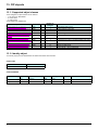
13. 7. Motor data object
The Motor data object acts as a motor parameter database.
Class code
Hexadecimal
16#28
Decimal
40
Object 28hex (Motor Data)
Path
16#28/01/06 = 40/1/6
16#28/01/07 = 40/1/7
16#28/01/09 = 40/1/9
16#28/01/0F = 40/1/15
CIP name
RatedCurrent
RatedVoltage
RatedFreq
BaseSpeed
CIP configuration parameter name
Motor Rated Cur
Motor Rated Volt
Motor Rated Freq
Motor Base Speed
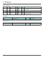
Telemecanique adaptation:
Path
16#28/01/06 = 40/1/6
16#28/01/07 = 40/1/7
16#28/01/09 = 40/1/9
16#28/01/0F = 40/1/15
Code
NCR
UNS
FRS
NSP
Altivar name
Rated mot. current
Rated motor volt.
Rated motor freq.
Rated motor speed
Logic address
16#2583 = 9603
16#2581 = 9601
16#2582 = 9602
16#2584 = 9604
Class attributes
Attribute ID
Access
Name
Need
Data type
Value
Details
1
Get
Revision
Opt.
UINT
2
—
2
Get
Max instance
Opt.
UINT
1
—
6
Get
Max ID number of class attribute
Opt.
UINT
7
—
7
Get
Max ID number of instance attribute
Opt.
UINT
15
—
Instance attributes
Attribute ID
Access
Name
Need
Data type
Value
Details
3
Get/Set
MotorType
Req.
USINT
7
6 = Wound rotor induction motor
7 = Squirrel cage induction motor
6
Get/Set
RatedCurrent
Req.
UINT
Depends on the
drive rating
[Rated mot. current] (nCr)
7
Get/Set
RatedVoltage
Req.
UINT
Depends on the
drive rating
[Rated mot. volt.] (UnS)
9
Get/Set
RatedFreq
Opt.
UINT
50/60
[Rated motor freq.] (FrS)
15
Get/Set
BaseSpeed
Opt.
UINT
Depends on the
drive rating
[Nom motor speed] (nSP)
Class service
Service code
Service name
Need
Description
16#0E
Get_Attribute_Single
Req.
Read an attribute
Service code
Service name
Need
Description
16#0E
Get_Attribute_Single
Req.
Read an attribute
16#10
Set_Attribute_Single
Opt.
Write an attribute
Instance service
53
13. CIP objects
13. 8. Control supervisor object
The Control supervisor object models the functions for managing all devices within the hierarchy of motor control devices.
Object 29hex (Control Supervisor)
Path
16#29/01/0D = 41/1/13
CIP name
FaultCode
CIP configuration parameter name
Fault Code
Telemecanique adaptation:
Path
16#29/01/0D = 41/1/13
Code
ERRD
Altivar name
CiA402 fault code
Logic address
16#219E = 8606
Class code
Hexadecimal
16#29
Decimal
41
Class attributes
Attribute ID
Access
Name
Need
Data type
Value
Details
1
Get
Revision
Opt.
UINT
2
—
2
Get
Max instance
Opt.
UINT
1
—
6
Get
Max ID number of class attribute
Opt.
UINT
7
—
7
Get
Max ID number of instance attribute
Opt.
UINT
17
—
Instance attributes
Attribute ID
Access
Name
Need
Data type
Details
3
Get/Set
Run Fwd
Req.
BOOL
On an edge (0 V1)
4
Get/Set
Run Rev
Opt.
BOOL
On an edge (0 V1)
5
Get/Set
NetCtrl
Opt.
BOOL
0: Local Control (Channel 1)
1: Network Control (default)
6
Get
State
Opt.
USINT
0 = Vendor Specific,
1 = Startup, 2 = Not_Ready, 3 = Ready,
4 = Enabled, 5 = Stopping,
6 = Fault_Stop, 7 = Faulted
7
Get
Running Fwd
Req.
BOOL
8
Get
Running Rev
Opt.
BOOL
9
Get
Ready
Opt.
BOOL
10
Get
Faulted
Req.
BOOL
12
Get/Set
FaultRst
Req.
BOOL
Fault reset (0 V1)
13
Get
FaultCode
Opt.
UINT
Refer to the Communication parameters manual:
DSP402 fault code (Errd)
15
Get
CtrlFromNet
Opt.
BOOL
0 = Local Control; 1 = Network Control
54
13. CIP objects
Class service
Service Code
Service name
Need
Description
16#0E
Get_Attribute_Single
Req.
Read an attribute
Service Code
Service name
Need
Description
16#0E
Get_Attribute_Single
Req.
Read an attribute
16#10
Set_Attribute_Single
Req.
Write an attribute
16#05
Reset
Req.
Drive reset
Instance service
Control supervisor state transition diagram
Non-Existent
Switch off
Switch on
Reset
Startup
Fault detected
Main power off
Faulted
Fault Reset
Initialization complete
Fault stop complete
Fault detected
Not_Ready
Main power on
Main power off
Fault_Stop
Fault detected
Ready
Stop complete
Run
Stopping
Stop
Enabled
55
13. CIP objects
13. 9. AC/DC Drive Object
The AC/DC Drive object models the functions (such as torque control and speed ramp) that are specific to drives.
Class code
Hexadecimal
16#2A
Decimal
42
Class attributes
Attribute ID
Access
Name
Need
Data Type
Value
Details
1
Get
Revision
Opt.
UINT
1
—
2
Get
Max instance
Opt.
UINT
1
—
6
Get
Max ID number of class attribute
Opt.
UINT
7
—
7
Get
Max ID number of instance attribute
Opt.
UINT
21
—
Instance attributes
Attribute ID
Access
Name
Need
Data type
Details
3
Get
AtReference
Opt.
BOOL
4
Get/Set
NetRef (1)
Req.
BOOL
0: Local speed setpoint (AI1 or AI2)
1: Speed setpoint via the network
5
Get/Set
NetProc
Opt.
BOOL
Not handled
6
Get/Set
Drive mode
Req.
USINT
1: Open loop
2: Closed loop (FVC)
7
Get
SpeedActual
Req.
INT
Output speed (rFrd)
8
Get/Set
SpeedRef
Req.
INT
Speed setpoint (LFrd)
9
Get
CurrentActual
Opt.
INT
Motor current (LCr)
10
Get/Set
CurrentLimit
Opt.
INT
[Mot. therm. current] (ItH)
11
Get
TorqueActual
Opt.
INT
Output torque (Otrn)
12
Get/Set
TorqueRef
Opt.
INT
Torque setpoint (LtCr)
18
Get/Set
AccelTime
Opt.
UINT
Acceleration time (ACCd)
19
Get/Set
DecelTime
Opt.
UINT
Deceleration time (dECd)
20
Get/Set
LowSpdLimit
Opt.
UINT
Parameter [Low speed] (LSP) converted in RPM
21
Get/Set
HighSpdLimit
Opt.
UINT
Parameter [High speed] (HSP) converted in RPM
Class service
Service code
Service name
Need
Description
16#0E
Get_Attribute_Single
Req.
Read an attribute
Service code
Service name
Need
Description
16#0E
Get_Attribute_Single
Req.
Read an attribute
16#10
Set_Attribute_Single
Opt.
Write an attribute
Instance service
56
13. CIP objects
13. 10. Assembly object
The Assembly object binds together the attributes of multiple objects so that information to or from each object can be communicated over
a single connection.
Assembly objects are static.
The assemblies in use can be modified through the parameter access of the network configuration tool (RSNetWorx).
The drive needs a power off to take into account a new assembly assignment.
Class code
Hexadecimal
16#04
Decimal
4
Class attribute
Attribute ID
Access
Name
Need
Data type
Value
Details
1
Get
Revision
Opt.
UINT
2
—
2
Get
Max instance
Opt.
UINT
105
13 defined instances
Instances supported
Instance
Name
Data size
20
ODVA Basic speed control output
4 bytes
21
ODVA Extended speed control output
4 bytes
22
ODVA Speed and torque control output
6 bytes
23
ODVA Extended speed and torque control output
6 bytes
100
Native drive output
16 bytes
103
Allen-Bradley® drive output
20 bytes
70
ODVA Basic speed control input
4 bytes
71
ODVA Extended speed control input
4 bytes
72
ODVA Speed and torque control input
6 bytes
73
ODVA Extended speed and torque control input
6 bytes
101
Native drive input
16 bytes
104
Allen-Bradley® drive input
20 bytes
The description of each instance is detailed in chapter 15. Device profiles
Instance attributes
Attribute ID
Access
Name
Need
3
Get/Set (1)
Data
Req.
Data type
Value
Details
(1) Set access is restricted to output instances only (instances 20, 21, 22, 23, 100 and 103).
Class service
Service code
Service name
Need
Description
16#0E
Get_Attribute_Single
Req.
Read an attribute
Instance service
Service code
Service name
Need
Description
16#0E
Get_Attribute_Single
Req.
Read an attribute
16#10
Set_Attribute_Single
Opt.
Write an attribute
57
13. CIP objects
13. 11. Application objects
Class code
Hexadecimal
16#70 to 16#A8
Decimal
112 to 424
Altivar parameters path
The Altivar parameters are grouped in classes.
Each application class has only 1 instance.
Each instance groups 200 parameters.
Each attribute in an instance relates to a parameter.
The first parameter registered in the first application class (class code: 16#70 = 112) has the logical address 3000.
Examples:
Logical address
3 000
3 100
3 200
64 318
Path Hexadecimal
16# 70 / 01 / 01
16# 70 / 01 / 65
16# 71 / 01 / 01
16# A2 / 1 / 77
Path decimal
112 / 1 / 1
112 / 1 / 101
113 / 1 / 1
418 / 1 / 119
Refer to the Communication parameters manual.
Class attributes
Attribute ID
Access
Name
Need
Data type
Value
1
Get
Revision
Opt.
UINT
1
2
Get
Max instance
Opt.
UINT
1
6
Get
Max ID number of class attribute
Opt.
UINT
7
7
Get
Max ID number of instance attribute
Opt.
UINT
X
Instance attributes
Attribute ID
Access
Name
Data type
Value
1
Get/Set
First parameter of the class
UINT / USINT
Value returned by the drive
...
...
...
...
...
X
Get/Set
Last parameter of the class
UINT / USINT
Value returned by the drive
Note: Depending on the parameter, write access may be prohibited. Refer to the Communication parameters manual for more information.
Class service
Service code
Service name
Need
Description
16#0E
Get_Attribute_Single
Req.
Read an attribute
Service code
Service name
Need
Description
16#0E
Get_Attribute_Single
Req.
Read an attribute
116#0
Set_Attribute_Single
Opt.
Write an attribute
Instances service
58
13. CIP objects
b Object 2Ahex (AC/DC Drive)
Path
16#2A/01/07 = 42/1/7
16#2A/01/08 = 42/1/8
16#2A/01/09 = 42/1/9
16#2A/01/0A = 42/1/10
16#2A/01/0B = 42/1/11
16#2A/01/0C = 42/1/12
16#2A/01/12 = 42/1/18
16#2A/01/13 = 42/1/19
16#2A/01/14 = 42/1/20
16#2A/01/15 = 42/1/21
CIP name
SpeedActual
SpeedRef
CurrentActual
CurrentLimit
TorqueActual
TorqueRef
AccelTime
DecelTime
LowSpdLimit
HighSpdLimit
CIP configuration parameter name
Speed Actual
Speed Reference
Current Actual
Current Limit
Torque Actual
Torque Reference
Accel Time
Decel Time
Low Speed Limit
High Speed Limit
Telemecanique adaptation:
Path
16#2A/01/07 = 42/1/7
16#2A/01/08 = 42/1/8
16#2A/01/09 = 42/1/9
16#2A/01/0A = 42/1/10
16#2A/01/0B = 42/1/11
16#2A/01/0C = 42/1/12
16#2A/01/12 = 42/1/18
16#2A/01/13 = 42/1/19
16#2A/01/14 = 42/1/20
16#2A/01/15 = 42/1/21
Code
RFRD
LFRD
LCR
ITH
Otrn
n.a.
ACCD
DECD
LSPD
HSPD
Altivar name
Output velocity
Speed setpoint
Motor current
Mot. therm. current
Output torque (Nm)
Torque setpoint (Nm)
CIP acceleration time
CIP deceleration time
CIP Low speed limit
CIP High speed limit
Logic address
16#219C = 8604
16#219A = 8602
16#0C84 = 3204
16#2596 = 9622
16#2A0B = 10763
16#2A0C = 10764
16#2A12 = 10770
16#2A13 = 10771
16#2A14 = 10772
16#2A15 = 10773
Unit Id
251
251
251
251
251
251
59
14. Explicit Messaging
The following example shows an example of explicit messaging: The value of the ACC parameter ( Modbus @ = 9001 / CIP address
16#2A:1:16#12 ) is modified when the variable "bit01" is toggled ON.
The detailed configuration of the message Box:
60
15. Device profiles
EtherNet/IP card provides several profiles:
• CIP AC drive profile (0x02) (default setting),
• Allen Bradley drive profile,
• Telemecanique: CiA 402 and I/O.
The profile is chosen by the selection of the right input assembly and output assembly.
In this manual, the chapter "Integration in RSLogix 5000" shows how the user may select the assemblies.
b List of assemblies
Output assemblies
Assembly name
CIP basic speed control output
CIP extended speed control output
CIP speed and torque control output
CIP extended speed and torque control output
Native drive output
Allen-Bradley® drive output
Number
20
21
22
23
100
103
Size
2 words (4 bytes)
2 words (4 bytes)
3 words (6 bytes)
3 words (6 bytes)
2 to 10 words (4 to 20 bytes)
2 to 10 words (4 to 20 bytes)
Number
70
71
72
73
101
104
Size
2 words (4 bytes)
2 words (4 bytes)
3 words (6 bytes)
3 words (6 bytes)
2 to 10 words (4 to 20 bytes)
2 to 10 words (4 to 20 bytes)
Input assemblies
Assembly name
CIP basic speed control input
CIP extended speed control input
CIP speed and torque control input
CIP extended speed and torque control input
Native drive input
Allen-Bradley® drive input
IMPORTANT REMARK:
For the assemblies 20 and 22, the default settings defines that the speed setpoint is originated from the terminals. To fully control the drive
from the network the following operation is required:
The object 2A/1/4 (netref) must be changed from 0 to 1 (byte). Such assignment can be done:
• By program, with an MSG() instruction block.
• With the Class instance editor:
(
61
15. Device profiles
b Assembly 20: CIP basic speed control output
Assembly mapping
Word number
0
1
Definition
CIP basic command word
Speed setpoint (rpm)
CIP basic command word
Bit 7
Not used
Bit 6
Not used
Bit 5
Not used
Bit 4
Not used
Bit 3
Not used
Bit 2
Fault reset (1)
Bit 1
Not used
0 = No command
1 = Fault reset
Bit 0
Run Forward (2)
0 = Stop
1 = Run
(1) Active on rising edge.
(2) Active on level.
Bit 15
Not used
Bit 14
Not used
Bit 13
Not used
Bit 12
Not used
Bit 11
Not used
Bit 10
Not used
Bit 9
Not used
Bit 8
Not used
Bit 3
Not used
Bit 2
Running
Bit 1
Not used
Bit 0
Faulted
b Assembly 70: CIP basic speed control input
Assembly mapping
Word number
0
1
Definition
CIP basic status word
Actual speed (rpm)
CIP basic status word
Bit 7
Not used
Bit 6
Not used
Bit 5
Not used
Bit 4
Not used
0 = Stopped
1 = Running
Bit 15
Not used
Bit 14
Not used
Bit 13
Not used
Bit 12
Not used
Bit 11
Not used
Bit 10
Not used
0 = No fault
1 = Fault
Bit 9
Not used
Bit 8
Not used
b Assembly 21: CIP extended speed control output
Assembly mapping
Word number
0
1
Definition
CIP extended command word
Speed setpoint (rpm)
CIP extended command word
Bit 7
Bit 6
Not used Network setpoint
Bit 5
Network command
0 = Setpoint by terminals
1 = Setpoint by network
Bit 15
Bit 14
Not used
Not used
(1) Active on rising edge.
62
Bit 4
Bit 3
Bit 2
Not used Not used Fault reset (1)
0 = Command by terminals
1 = Command by network
Bit 13
Not used
Bit 12
Not used
0 = No command
1 = Fault reset
Bit 11
Not used
Bit 10
Not used
Bit 1 Bit 0
Run forward / reverse
00 = Quick stop
01 = Run forward
10 = Run reverse
11 = Freewheel stop
Bit 9
Not used
Bit 8
Not used
15. Device profiles
b Assembly 71: CIP extended speed control input
Assembly mapping
Word number
0
1
Definition
CIP extended status word
Actual speed (rpm)
CIP extended status word
Bit 7
At reference
0 = Reference
not reached
1 = Reference
reached
Bit 6
Setpoint from
network
0 = Setpoint
from terminals
1 = Setpoint
from network
Bit 5
Bit 4
Command from Ready
0 = Not ready
network
0 = Command 1 = Ready
from terminals
1 = Command
from network
Bit 3
Bit 2
Running forward / reverse
Bit 1
Warning
00 = Stopped
01 = Running forward
10 = Running reverse
11 = Not used
0 = No warning
1 = Warning
Bit 15
Not used
Bit 14
Not used
Bit 13
Not used
Bit 11
Not used
Bit 12
Not used
Bit 0
Not used
Bit 10
Bit 9
Bit 8
Bit 8 to bit 10 are used for the drive state
000 = Not used
001 = Startup
010 = Not Ready
011 = Ready
100 = Enabled
101 = Stopping
110 = Fault Stop
111 = Faulted
b Assembly 22: CIP speed and torque control output
Assembly mapping
Word number
0
1
2
Definition
CIP basic command word (1)
Speed setpoint (rpm)
Torque setpoint (Nm)
(1) Refer to assembly 20.
b Assembly 72: CIP speed and torque control input
Assembly mapping
Word number
0
1
2
Definition
CIP basic status word (1)
Actual speed (rpm)
Actual torque (Nm)
(1) Refer to assembly 70.
b Assembly 23: CIP extended speed and torque control output
Assembly mapping
Word number
0
1
2
Definition
CIP extended command word (1)
Speed setpoint (rpm)
Torque setpoint (Nm)
(1) Refer to assembly 21.
63
15. Device profiles
b Assembly 73: CIP extended speed and torque control input
Assembly mapping
Word number
0
1
2
Definition
CIP extended status word (1)
Actual speed (rpm)
Actual torque (Nm)
(1) Refer to assembly 71.
b Assembly 100: Native drive output
Assembly mapping
Word number
0
1
2
3
4
5
6
7
Definition
Control word
Velocity setpoint
Scanner write word 1
Scanner write word 2
Scanner write word 3
Scanner write word 4
Scanner write word 5
Scanner write word 6
Altivar 71/61 assignment
Word number
0
1
2
3
4
5
6
7
Code
Name
NC1 Communication scanner, value of write word 1
(default value :CMD, Control word)
NC2 Communication scanner, value of write word 2
(default value: LFRD, velocity setpoint)
NC3 Communication scanner, value of write word 3
NC4 Communication scanner, value of write word 4
NC5 Communication scanner, value of write word 5
NC6 Communication scanner, value of write word 6
NC7 Communication scanner, value of write word 7
NC8 Communication scanner, value of write word 8
Logic address
16#31D9 = 12761
16#31DA = 12762
16#31DB = 12763
16#31DC = 12764
16#31DD = 12765
16#31DE = 12766
16#31DF = 12767
16#31E0 = 12768
Note: The default assignment of NC1 and NC2 must be changed to "Not assigned".
64
15. Device profiles
b Assembly 101: Native drive input
Assembly mapping
Word number
0
1
2
3
4
5
6
7
Definition
Scanner read word 1
Scanner read word 2
Scanner read word 3
Scanner read word 4
Scanner read word 5
Scanner read word 6
Scanner read word 7
Scanner read word 8
Altivar 71/61 assignment
Word number
0
1
2
3
4
5
6
7
Code
Name
NM1 Communication scanner, value of read word 1
(default value: Status word, ETA)
NM2 Communication scanner, value of read word 2
(default value: Velocity actual value, RFRD)
NM3 Communication scanner, value of read word 3
NM4 Communication scanner, value of read word 4
NM5 Communication scanner, value of read word 5
NM6 Communication scanner, value of read word 6
NM7 Communication scanner, value of read word 7
NM8 Communication scanner, value of read word 8
Logic address
16#31C5 = 12741
16#31C6 = 12742
16#31C7 = 12743
16#31C8 = 12744
16#31C9 = 12745
16#31CA = 12746
16#31CB = 12747
16#31CC = 12748
65
15. Device profiles
b Assembly 103: Allen-Bradley® drive output
Assembly mapping
Word number
0
1
2
3
4
5
6
7
8
9
Definition
Allen-Bradley® drive logic command
Standardized speed setpoint (reference)
Scanner write word 1
Scanner write word 2
Scanner write word 3
Scanner write word 4
Scanner write word 5
Scanner write word 6
Scanner write word 7
Scanner write word 8
Altivar 71/61 assignment
Word number
0
1
2
3
4
5
6
7
8
9
Code
n.a.
LFR
NC1
NC2
NC3
NC4
NC5
NC6
NC7
NC8
Name
Allen-Bradley® drive logic command
Frequency setpoint
Communication scanner, value of write word 1
Communication scanner, value of write word 2
Communication scanner, value of write word 3
Communication scanner, value of write word 4
Communication scanner, value of write word 5
Communication scanner, value of write word 6
Communication scanner, value of write word 7
Communication scanner, value of write word 8
Logic address
n.a.
16#2136 = 8502
16#31D9 = 12761
16#31DA = 12762
16#31DB = 12763
16#31DC = 12764
16#31DD = 12765
16#31DE = 12766
16#31DF = 12767
16#31E0 = 12768
Note: The default assignment of NC1 and NC2 must be changed to another value or to not assigned..
66
15. Device profiles
b Allen-Bradley® drive logic command
The logic command is a 16-bit word of control produced by the scanner and consumed by the EtherNet/IP card.
If enabled, the Logic command word is always word 0 in the output image.
Bit 7
MOP Increment
Bit 6
Local control
Bit 5 Bit 4
Direction
Bit 3
Clear faults (3)
Jog
Bit 1
Start (2)
Bit 0
Stop (1)
0 = Not Increment
1 = Increment
0 = No local
control
1 = Local control
00 = No command (4)
01 = Forward command
10 = Reverse command
11 = Hold direction
control
0 = Not clear faults
1 = Clear faults
0 = Not jog
1 = Jog
0 = Not start
1 = Start
0 = Not stop
1 = Stop
Bit 15
MOP Decrement
Bit 14
Bit 13
Reference select
Bit 12
0 = Not decrement
1 = Decrement
000 = No command (7)
001 = Setpoint 1 channel (Fr1)
010 = Setpoint 2 channel (Fr2)
011 = Ref. 3 (Preset 3)
100 = Ref. 4 (Preset 4)
101 = Ref. 5 (Preset 5)
110 = Ref. 6 (Preset 6)
111 = Ref. 7 (Preset 7)
Bit 2
Bit 11 Bit 10
Bit 9 Bit 8
Decel rate
Accel rate
00 = No command (6)
01 = Decel rate 1 command
10 = Decel rate 2 command
11 = Hold decel rate
00 = No command (5)
01 = Accel rate 1 command
10 = Accel rate 2 command
11 = Hold accel rate
(1) Stop: Active at level.
(2) Start: Active on rising edge. A Not stop condition (logic 0 = 0) must first be present before a Start condition (logic 1 = 1) will start the drive.
(3) Clear faults: Active on rising edge. To perform this command, the value must switch from "0" to "1."
(4) Direction \ No command: If a direction is selected acts like Hold direction control.
(5) Accel rate \ No command: If a rate is selected acts like Hold accel rate.
(6) Decel rate \ No command: If a rate is selected acts like Hold decel rate.
(7) Reference select \ No command: If a rate is selected acts like Hold command.
b Altivar 71/61 assignment
Bit 7
Not used
Bit 6
Not used
Bit 5 Bit 4
Direction
00 = No command (4)
01 = Forward command
10 = Reverse command
11 = Hold direction control
Bit 15
Not used
Bit 14
Bit 13
Setpoint select
Bit 12
Bit 11
Not used
Bit 10
Not used
Bit 3
Clear faults (3)
0 = Not clear faults
1 = Clear faults
Bit 2
Not used
Bit 1
Start (2)
Bit 0
Stop (1)
0 = Not start
1 = Start
0 = Not stop
1 = Stop
Bit 9
Not used
Bit 8
Not used
000 = No command
001 = Terminals
010 = Control by network
011 = Preset 3
100 = Preset 4
101 = Preset 5
110 = Preset 6
111 = Preset 7
67
15. Device profiles
b Standardised setpoint
The setpoint (16 bits only) is produced by the controller and consumed by the EtherNet/IP card.
If enabled, the setpoint is always word 1 in the output image.
The setpoint value is a standardised (e.g. scaled) value; it is not an engineering value.
Telemecanique adaptation
[Frequency setpoint] (LFr) shall be configured in high resolution: standardised value on 16 signed bits at maximum frequency. The value
32767 corresponds to the parameter [Max frequency] (tFr). The default value of the parameter [Max frequency] (tFr) is 60 Hz, and
the resolution is then approximately 0.0018 Hz.
Note:
The commanded maximum speed can never exceed the value of the parameter [High speed] (HSP).
The table below shows example setpoints and their results on an Altivar drive that has its parameter [Max frequency] (tFr) set to 130 Hz
and its parameter [High speed] (HSP) set to 60 Hz.
Scale
Setpoint value
32767 (1)
16384
8192
0
Percent
100%
50%
25%
0%
Value
130 Hz
65 Hz
32.5 Hz
0 Hz
Output speed
60 Hz (2)
60 Hz (2)
32.5 Hz
0 Hz
Feedback value
15123 (3)
15123 (3)
8192
0
(1) A value of 32767 is equivalent to the parameter [Max frequency] (tFr) frequency value. Values greater than 32767 reverse speed.
(2) The drive runs at 60 Hz instead of 130 Hz or 65 Hz because the parameter [High speed] (HSP) sets 60 Hz as the maximum speed.
(3) The feedback value is also scaled based on the value of the parameter [Max frequency] (tFr), for example, 60/130 = 0.46 so
32767 x 0.46 = 15123.
b Assembly 104: Allen-Bradley® drive input
Assembly mapping
Word number
0
1
2
3
4
5
6
7
8
9
Definition
Allen-Bradley® drive logic status
Speed feedback (actual value)
Scanner read word 1
Scanner read word 2
Scanner read word 3
Scanner read word 4
Scanner read word 5
Scanner read word 6
Scanner read word 7
Scanner read word 8
Word number
0
1
2
3
4
5
6
7
8
9
Code
n.a.
RFR
NM1
NM2
NM3
NM4
NM5
NM6
NM7
NM8
Name
Allen-Bradley® drive logic status
Output frequency
Communication scanner, value of read word 1
Communication scanner, value of read word 2
Communication scanner, value of read word 3
Communication scanner, value of read word 4
Communication scanner, value of read word 5
Communication scanner, value of read word 6
Communication scanner, value of read word 7
Communication scanner, value of read word 8
Logic address
n.a.
16#0C82 = 3202
16#31C5 = 12741
16#31C6 = 12742
16#31C7 = 12743
16#31C8 = 12744
16#31C9 = 12745
16#31CA = 12746
16#31CB = 12747
16#31CC = 12748
Note: The default assignment of NM1 and NM2 must be changed to "Not assigned".
68
15. Device profiles
b Allen-Bradley® drive logic status
The Logic Status is a 16-bit word of status produced by the EtherNet/IP card and consumed by the scanner.
If enabled, the Logic status word is always word 2 in the input image.
Bit 7
Fault
Bit 6
Alarm
Bit 5
Decelerating
Bit 4
Accelerating
Bit 3
Bit 2
Bit 1
Actual direction Command direction Active
0 = No fault 0 = No alarm 0 = Not decelerating 0 = Not accelerating 0 = Reverse
1 = Fault
1 = Alarm
1 = Decelerating
1 = Accelerating
1 = Forward
Bit 15
Reference
Bit 14
Bit 13
Bit 12
0000 = Ref A auto
0001 = Ref B auto
0010 = Preset 2 auto
0011 = Preset 3 auto
0100 = Preset 4 auto
0101 = Preset 5 auto
0110 = Preset 6 auto
0111 = Preset 7 auto
1000 = Term blk manual
1001 = DPI 1 manual
1010 = DPI 2 manual
1011 = DPI 3 manual
1100 = DPI 4 manual
1101 = DPI 5 manual
1110 = DPI 6 manual
1111 = Jog reference
Bit 11
Local control
Bit 10
0 = Reverse
1 = Forward
Bit 0
Ready
0 = Not active 0 = Not ready
1 = Active
1 = Ready
Bit 9
Bit 8
At speed
000 = Port 0 (TB)
001 = Port 1
010 = Port 2
011 = Port 3
100 = Port 4
101 = Port 5
110 = Port 6
111 = No local
0 = Not at reference
1 = At reference
Telemecanique adaptation
Bit 7
Fault
Bit 6
Alarm
Bit 5
Decelerating
Bit 4
Accelerating
Bit 3
Bit 2
Bit 1
Actual direction Command direction Running
0 = No fault 0 = No alarm 0 = Not decelerating 0 = Not accelerating 0 = Reverse
1 = Fault
1 = Alarm
1 = Decelerating
1 = Accelerating
1 = Forward
Bit 15
Bit 14
Setpoint source
Bit 13
0000 = Terminals
0001 = not used
0010 = Preset 2
0011 = Preset 3
0100 = Preset 4
0101 = Preset 5
0110 = Preset 6
0111 = Preset 7
1000 = not used
1001 = Graphic display terminal
1010 = Modbus
1011 = CANopen
1100 = PowerSuite
1101 = EtherNet/IP card
1110 = Controller inside
1111 = not used
Bit 12
Bit 11
Control source
Bit 10
000 = Terminals
001 = Graphic display terminal
010 = Modbus
011 = CANopen
100 = PowerSuite
101 = EtherNet/IP card
110 = Controller inside
111 = not used
0 = Reverse
1 = Forward
Bit 9
Bit 0
Ready
0 = Not active 0 = Not ready
1 = Active
1 = Read
Bit 8
At speed
0 = Not at reference
1 = At reference
Note: When the value of Setpoint source (bits 12, 13, 14 and 15) is Preset speed x, it means that the corresponding command is given by
the assembly 103 via Setpoint select (bits 12,13 and 14) (not by the terminals).
69
16. Configuring an ATV71/61 in replacement of a Powerflex® drive
This chapter illustrates of to proceed to exchange Powerflex® drive an ATV71. This example has been realized by RSlogix® software.
There are three way to configure the drive equipped with an EtherNet/IP card.
IMPORTANT NOTE:
The ATV71/61 provides several assembly sets. Assembly 103 and 104 emulates the Powerflex drive assemblies. But for compatibility
reasons these assemblies can also use number 1 and 2. This means that in the ATV71/61:
• output assembly 103 and 2 are identical,
• input assembly 104 and 1 are identical.
In the following example, we start with an application based on a network made of a single VSD (a Powerflex drive). The following pages
describe how to replace it by an ATV71 .
70
16. Configuring an ATV71/61 in replacement of a Powerflex® drive
Put the RSlogix environment Offline:
Then edit the module properties of the "ETHERNET MODULE Powerflex" by double-clicking in the navigation tree.
71
16. Configuring an ATV71/61 in replacement of a Powerflex® drive
Notice that only the Module Name is changed.
Here, we have used Assemblies 1 and 2 (As Powerflex VSD).
But Assemblies 103 and 104 could also be used, like in the dialog box below.
Confirm the modification by OK, save the project and download it to the PLC.
72
16. Configuring an ATV71/61 in replacement of a Powerflex® drive
Now, switch to RSnetworx, The old configuration is always displayed:
Browse the whole Network:
73
16. Configuring an ATV71/61 in replacement of a Powerflex® drive
Once the network has been scanned, you should obtain this:
This last screen shows the data screen of the ATV71.
74
atv61/71_Ethernet/IP_EN_V1
2007-10