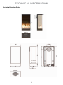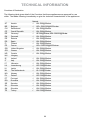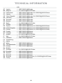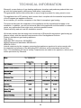
1
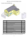
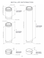
User- and installation manual
Sirius
WARNING - THE COMBUSTION CHAMBER OF THIS
STOVE SHOULD ONLY BE OPENED AND SERVICED BY A
REGISTERED GAS INSTALLER
(i.e. GAS SAFE REGISTERED ENGINEER[GB])
These instructions should be left with the customer
for future reference
This Manual Covers the following appliances:
Sirius
Contents
GENERAL INFORMATION............................................................................................................3
Important Safety Notice..................................................................................................................3
General Fitting Information....................................................................................................4
USER INFORMATION...................................................................................................................5
Remote Control Electronic Ignition System RCE GV60................................................................5
INSTALLER INFORMATION.......................................................................................................10
Ventilation............................................................................................................................10
General Balanced Flue Notes / Appliance Fireplace installation.........................................10
Terminal Locations Wall Mounting.......................................................................................12
Terminal Locations Roof Termination...................................................................................13
Concentric Flue Parts Identification.....................................................................................14
Rigid Balanced Flue Connection Possibilities......................................................................21
Vertical Roof Terminations...................................................................................................22
Installing Remote Control Electronic Ignition System GV60........................................................23
Arranging The Ceramic Fire-bed..................................................................................................24
Log Arrangements...............................................................................................................24
Gravel Arrangements...................................................................................................................25
COMMISSIONING THE APPLIANCE..........................................................................................25
Installation tips.............................................................................................................................26
Installing gasfire Sirius .............................................................................................................26
Servicing Instructions...................................................................................................................28
Troubleshooting............................................................................................................................29
TECHNICAL INFORMATION.......................................................................................................31
Dimensions...................................................................................................................................31
Technical Details..........................................................................................................................32
Warranty.......................................................................................................................................35
2
GENERAL INFORMATION
Important Safety Notice
a registered gas installer be employed for this
task. The engineer will provide you with information about the safety limits of the installation and
should fix a notice plate in a place where it can
be readily seen.
This appliance has a ceramic Fire-bed arrangement; this contains Refractory Ceramic Fibres,
which are man-made vitreous silicate fibres. Excessive exposure to these materials can cause
irritation to eyes, skin and respiratory organs.
Hence we recommend that when handling these
materials the release of dust should be kept to
a minimum. During installation and servicing we
recommend that a HEPA filtered vacuum be used
to remove any dust and soot in and around the
fire. If any of the ceramic fire-bed components
need to be replaced we recommend that the removed parts be sealed in a heavy-duty polythene
bag, and be labelled as RCF waste. RCF is not
“Hazardous waste” and can be disposed of at a
licensed tipping site for the disposal of industrial
waste.
This appliance is designed as an efficient heating
device and consequently all body parts become
very hot in use. Except for the control knob and
control access door, which are designed to stay
cool, all other parts are working surfaces and
should not be touched.
The glass and frame on this appliance acts as
a fireguard conforming to BS: 1945 – 1971 and
satisfies the Heating Appliance (Fireguards)
regulations 1991. No part of the window or frame
should be permanently removed. It does not give
protection for young children aged or infirm,
extra guarding(conforming to BS8423: 2002)
should be considered so the special hazards that
exist in nurseries and other places where there
are young children, aged or infirm persons are
minimized.
The appliance incorporates a permanent pilot.
This is located on the front of the burner, and
must not be adjusted by the installer. This system
must not be put out of operation, and if any parts
require changing, only original manufacturer parts
shall be used.
Bearing in mind that the heat given off by this
appliance may affect articles placed close to it,
curtains should not be placed within 30cm.
This appliance is designed to be used either Natural or LPG gas however, each individual appliance
is only capable of running off the type of gas
specified at the time of purchase. It is important
to note that once a type of gas has been specified the stove cannot run off any other type. The
type of gas that your stove is capable of burning
is stated on the data information panel.
The appliance is not designed as a dryer. It is not
therefore recommended that the appliance be
used in such a manner. Do not place any articles
within 30cm of this appliance as this may result
in damage to the articles.
The installation must be carried out in accordance
with the following regulations:
This appliance has been designed, tested and
approved to meet standards in place for product use, performance and safety. Installation of
your appliance must comply with current building regulations. It is therefore recommend that
The Building Regulations issued by the Depart
3
GENERAL INFORMATION
ment of the Environment, the Building Standards
(Scotland) (Consolidation) Regulations issued by
the Scottish Development Department.
If the appliance is to be fitted against a wall with
combustible cladding, the cladding must be removed from the area covered, above and around.
BS 5440 part 1, BS 5871 part 2 and BS 6891.
As on all heat producing appliances, soft furnishes such as blown vinyl wallpaper placed too
near to the appliance may become scorched or
discoloured. This should be born in mind when
installing the appliance.
In the Republic of Ireland the installation must
also conform to the relevant standards, particularly in regard to flue sizing and ventilation. Refer
to documents IS813, ICP3, IS327 and any other
rules in force.
Note:
Since the appliance is a source of heat, circulation
of air occurs. Therefore it is of importance that you
do not use the appliance shortly after a renovation
of the home. Because of the natural circulation
of air, moist and volatile components from paint,
building materials, carpet etc. will
be attracted. These components can settle themselves down onto cold surfaces in the form of soot.
This appliance must be installed in accordance
with the rules in force and used only in a sufficiently ventilated space, and is intended for use
on a gas installation with a governed meter.
Before installation, ensure that the local distribution conditions (identification of the type of gas
and pressure) and the adjustment of the appliance
are compatible. The technical specification of this
appliance is given on the rear page of this manual.
Prevention of Rust:
Always switch off the fire completely after use.
Do not leave pilot flame on.This saves gas
and prevents corroding of your fire.
Do not use the appliance if the glass front door
or panel has been broken, removed or is open.
General Fitting Information
Inlet pipe connection
8mm compression
Chimney requirements Balanced Flue
Flue monitor
Permanent Pilot
Positioning the appliance
This appliance has been designed to hang
against a wall. This wall must be made of noncombustible and heat resistant material.
User control: Variable rotary control inc. integrated Piezo ignition, Permanent pilot facility, Flame
failure device and Oxygen Depletion Cut-out.
The plaster of the wall has to be resistant to a high
temperature. Use therefore the plaster materials
especially made for this to prevent discoloring
(min. 100 degrees temperature resistant).
Before installation of these appliances, the area
into which the fire is to be fitted must be cleared
of all debris (including dust), in particular combustible material.
4
Remote control electronic ignition
system RCE GV60
- temperature display in degrees Celsius or
Fahrenheit;
- time;
thermostat function;
The appliance
supplied with
a remotesyscontrol. --temperature
display in degrees Celsius or
Remote
control iselectronic
ignition
temperature
display
in degrees
Celsius or
Remote
control
electronic
ignition
timer
for
thermostat
function.
controlling the flame height and switch- Fahrenheit;
temIgnition,
RCE GV60
Fahrenheit;
system
RCE
GV60
ing off
are performed
by the remote control that - time;
- time;Setting the communication code
operates ais receiver
thea control
The appliance
supplied in
with
remote hatch.
control.For - thermostat function;
- thermostattofunction;
The appliance
is suppliednowith
a remote
control.
putting
the application
some
appliances,
control
hatch
supplied. -Prior
timer for
thermostat
function. into operation, a
Ignition,
controlling
the flame
height
andisswitchtimer
for
thermostat
function.
Ignition,
controlling
height
and switchcommunication code must be set between the
In are
that
case, the
the flame
receiver
is placed
under
ing off
performed
by
the remote
control
that the
ing offappliance.
are performed
by the remote
controlcontrol
that
remote control and the receiver. The code is choTheinreceiver
andhatch.
remote
operates a receiver
the control
For someare Setting the communication code
Setting
communication
code available codes.
operates
a receiver
in the receiver
control hatch.
For
senthe
randomly
the 65000
battery
powered.
requires
Prior
to puttingfrom
the application
into operation, a
appliances,
no
controlThe
hatch is supplied.
In 4that
Prior to
putting
the
application
into
operation,
a
somepenlite
appliances,
no control
hatchthe
is remote
supplied.
As
a
result,
the
chance
that
other
remote
controls
(AA
type)
batteries,
control
communication code must be set
between
the
case, the receiver is placed under the appliance.
communication
code
must
be
set code
between
the the
In thatrequires
case, the
receiver
is
placed
under
the
near
you
are
using
the
same
and
affect
3 xremote
AAA penlites
The receiver and
control .At
are normal
battery use,
pow- the remote control and the receiver. The code is choremote
control and
the receiver.
The code
choappliance.
The
receiver
and
remote
control
are
operation
of your
very is
small.
will have
an average
life of one year. sen
randomly
fromappliance
the 65000isavailable
codes. As
ered.batteries
The receiver
requires
4
sen randomly from the 65000 available codes.
battery
powered.
The
receiver
requires
4
You(AA
cantype)
also use
an optional
adapter.control
Ask your a result, the chance that other remote controls
penlite
batteries,
the remote
As a result,
chance
that other
remotebelow:
controls
penliteinstaller
(AA type)
batteries,
the
remote
control
Followthe
the
procedure
described
information.
that case
requires 3 x for
AAA
penlites .AtInnormal
use,you
thewill near you are using the same code and affect the
aredown
usingthe
the same button
code and
the
requires
AAAVpenlites
.At normal
use,
the near you
Hold
onaffect
the
receiver,
need3will
ax 230
appliance.
operation
of yourreset
appliance is very
small.
batteries
have connection
an averagenear
life your
of one
year.
your
appliance
is very small.
batteries will have an average life of one year. operation
untilof
you
hear
two consecutive
sound signals
You can also use an optional adapter. Ask your
You can also use an optional adapter. Ask your
(see fig.
After thedescribed
second, below:
longer signal,
Follow
the2).
procedure
installer for information. In that case you will need
procedure
described
below:
installer for information. In that case you will Followletthe
godown
of thethe
reset
button.
Hold
reset
button on the receiver,
a 230 V connection near your appliance.
down the
reset button on the receiver,
need a 230 V connection near your appliance. Hold Press
button
until you
hear two consecutive sound signals
until you hear two consecutive sound signals
(see fig. 2). After the second, longer signal, let
(see fig.
2). After
the control
second,within
longer20
signal,
onof
the
seconds,
go
theremote
reset button.
let gountil
of the reset
button.
hear
a sound signal: this is the
Press you
button
Pressconfirmation
button
of a correct communication.
USERINFORMATION
INFORMATION
USER
!Caution
When
installing
a new
remote conon
the remote
control
within
20 seconds,
until
on the
remote
control
within
20
seconds,
trol
or
receiver,
you
must
set
a
new
commuyou hear a sound signal: this is the confirmauntil nication
you hearcode.
a sound signal: this is the
tion of a correct
communication.
confirmation of a correct communication.
!Caution When installing a new remote control
!Caution When installing a new remote conor receiver, you must set a new communicatrol or receiver, you must set a new commuThe appliance’s standard functions such as igni- tion code.
nication code.
tion, controlling the flame height, standby (pilot
burner) position and switching off ,are performed
in the MAN position.
the display
of the
remote
The appliance’s
standardInfunctions
such
as igniThe appliance’s
standard
functions
as ignican see
theflame
letters
MAN.such
tion, you
controlling
the
height,
standby (pilot
tion, controlling
the
height,
standby
(pilot
In addition,
theflame
remote
control
canperformed
also
be used
burner)
position and
switching
off ,are
burner)
position
and switching
off ,are performed
set aposition.
number
of the
additional
in thetoMAN
In
displayfunctions:
of the remote
in the MAN position. In the display of the remote
you can see the letters MAN.
you can see the letters MAN.
In addition, the remote control can also be used
In addition, the remote control can also be used
to set a number of additional functions:
to set a number of additional functions:
1
1
2
2
5
5
5
USER
INFORMATION
USER
INFORMATION
USER
INFORMATION
MAN
MANposition
position
MAN position
ByBybriefly
brieflypressing
pressingthe
theSET
SETbutton,
button,you
you will
will go
go
By briefly pressing the SET button, you will go
through
the
following
functions:
through the following functions:
through the following functions:
MAN
→ →TEMP
→ (P*)TIMER
→
MAN→→ TEMP
TEMP
TEMP
→ (P*)TIMER
MAN →
TEMP → TEMP → (P*)TIMER
MAN
→ MAN
→ MAN
where,
where,depending
dependingononthe
thetimer
timersetting:
setting:
where, depending on the timer setting:
(P*)
is
displayed
as
P1
,
,
P1
,,
(P*) is displayed as P1 , , P1 , P2
, P2
(P*) is displayed as P1 , , P1
, P2
,
P2P2 . .
P2
.
✹
ow
llo
I gIngi nt ei t et h teh ea pappl ipalni ac n
e c ea s a sf o l fl o
s :w s :
Ignite the appliance as follows:
S e button
t button
n t hgas
e g acontrol
s contro
Set
A A
ono the
tol t o
Set button A on the gas control to
(button
B is
controlled
automatically).
ONON
(button
B is
controlled
automatically).
ON (button B is controlled automatically).
The
gas
control
locatedininthe
thecontrol
controlhatch
hatch or
The
gas
control
is islocated
The gas control is located in the control hatch
or is
is placed
placed under
under the
the appliance.
appliance.
or is placed under the appliance.
✹
You
position by
Youcan
canalso
alsogo
goback
backto
to the
the MAN
MAN position
by
You can also go back to the MAN position by
pressing
the
button
(large
flame)
or
Simultaneously
press
buttons
pressing the button
(large flame) or Simultaneously
press
thethe
buttons
pressing the button
(large flame) or Simultaneously press the buttons
(small
flame).
and
remote
control.
(small
flame).
and
onon
thethe
remote
control.
(small flame).
and
on the remote control.
!Caution
- When
pressing
the buttons
(with the
!Caution
- When
pressing
the buttons
!Caution - When pressing the buttons
exception
the SET button),
the transmission
(with theofexception
of the SET
button), the
(with the exception of the SET button), the
symbol
(
)symbol
will appear
indicate
that
transmission
(
)towill
appear
to
transmission symbol (
) will appear to
transmission
is
taking
place
between
the
remote
indicate that transmission is taking place
indicate that transmission is taking place
control
andthe
theremote
receiver;
between
control and the receiver;
between the remote control and the receiver;
- -The
receiver
acknowledges
transmission
The receiver acknowledges the
the transmission
- The receiver acknowledges the transmission
with
a sound
signal;
with
a sound
signal;
with a sound signal;
- -The
appliance
The appliancewill
will automatically
automatically enter
enter the
the
- The appliance will automatically enter the
standby
position,
if there
is no
transmission
for
standby
position,
if there
is no
transmission
standby position, if there is no transmission
6 for
hours.
6 hours.
for 6 hours.
Set
the
remote
control
to the
MANMAN
position.
Set
the
remote
control
to the
position.
Set the remote control to the MAN position.
Ignition
Ignition
Ignition
Caution
- During
the ignition
process,
you areyou
not
Caution
- During
the ignition
process,
Caution - During the ignition process, you
allowed
operate to
control
button
B
are nottoallowed
operate
control
button B
are not allowed to operate control button B
onon
the
gas
control
manually
the
gas
control
manually
on the gas control manually
- Always
wait
5
minutes
- Always wait 5 minutesafter
afterthe
thepilot
pilot burner
burner
- Always wait 5 minutes after the pilot burner
has
hasgone
goneout,
out,before
beforeyou
youre-ignite
re-ignite
has gone out, before you re-ignite
the
appliance;
the appliance;
the appliance;
33
BB
AA
buttons
when
a short
sound
LetLet
gogo
of of
thethe
buttons
when
a short
sound
Let go of the buttons when a short sound
signal
indicates
that
ignition
process
signal
indicates
that
thethe
ignition
process
hashas
signal indicates that the ignition process has
been
started.
been
started.
been started.
succession:
In In
succession:
In succession:
- thecontinuous
continuoussignals
signals will
will indicate
- the
indicate that
thatthe
theigni- the continuous signals will indicate that the
tion process
ignition
processisisactive;
active;
ignition process is active;
a short
sound
signalwill
willindicate
indicatethat
thatthe
theigniignition
- a- short
sound
signal
- a short sound signal will indicate that the igniprocess
has
finished;
tion
process
has
finished;
tion process has finished;
- the
appliance
automatically
switch
through
- the
appliance
willwill
automatically
switch
through
- the appliance will automatically switch through
highest
position
of the
main
burner,
which
to to
thethe
highest
position
of the
main
burner,
which
to the highest position of the main burner, which
start
burn
a few
seconds.
willwill
start
to to
burn
in in
a few
seconds.
will start to burn in a few seconds.
Caution
- Ifthe
thepilot
pilot burner
Caution
- If
burner is
isnot
notburning
burningafter
Caution - If the pilot burner is not burning
3 ignition
attempts,
youyou
must
close
the gas
after
3 ignition
attempts,
must
close
the tap
after 3 ignition attempts, you must close the
and
the
installer;
gas
tapcall
and
call
the installer;
gas tap and call the installer;
When
igniting
pilot
burner,
- When igniting thethe
pilot
burner,
youyou
willwill
hearhear
- When igniting the pilot burner, you will hear
sound
signals.After
Afterthe
the last
last short
sound
signals.
short sound
soundsigsound signals. After the last short sound
nal, the
burner
should
be largely
ignited
signal,
themain
main
burner
should
be largely
signal, the main burner should be largely
withinwithin
aboutabout
10 seconds.
If thisIf is
not
ignited
10 seconds.
this
is the
ignited within about 10 seconds. If this is
case,
you must
close
the the
gasgas
taptap
and
warn
not
the case,
you must
close
and
not the case, you must close the gas tap and
your
installer;
warn
your
installer;
warn your installer;
If
the
appliance
igniteswith
with a
a pop
- If the appliance ignites
pop sound,
sound,you
- If the appliance ignites with a pop sound,
must
close
thethe
gas
taptap
and
you
must
close
gas
and
you must close the gas tap and
contact
your
installer.
contact your installer.
contact your installer.
!Tip
A little
motor
start
to run
when
!Tip
A little
motor
willwill
start
to run
when
the the
!Tip A little motor will start to run when the
main
burneroperates,
operates,you
you will
will be
main
burner
beable
abletotohear
main burner operates, you will be able to
it. it.
hear
hear it.
66
6
USER INFORMATION
Flame height / standby
The flame height can be adjusted continuously by
using the buttons
and
Time
The display can indicate time.
After placing the battery or simultaneously pressing
(large flame) and
By continuing to lower the flame height, the appliance can be set to the standby position; this
means that only the pilot burner will still be burning.
Press button
(small flame) to lower the
flame height and/or to set the appliance in the
standby position.
Press the button
(large flame) to raise the
flame height and/or to switch on the main burner
from the standby (pilot burner) position.
(small flame), the time indication will flash on the
display and you will be able
to adjust the time.
Simultaneously press and until the time indication
flashes on the display.
Press the button
(large flame)
to set the hours.
Press the button
minutes.
(small flame) to set the
Caution - If you continue to press down button
Press OFF
to return to the MAN position,
or wait for the system to automatically return to
the MAN position.
(large flame) on the remote control,
the main burner should be largely ignited
within about 10 seconds. If this is not the
case, you must close the gas tap and warn
your installer;
- If the appliance ignites with a pop sound,
you must close the gas tap and contact your
installer.
Thermostat function
Using the thermostat function you can set
two temperatures, which can be controlled
thermostatically. These temperatures are referred
to as day temperature and night temperature.
The
TEMP and
TEMP symbols on
the display refer to day and night temperature
respectively.
The room temperature is compared to the set
day/night temperature and then the flame height
is automatically controlled in order to reach the
set temperature.To be able to use the day/night
temperature function, the appliance must be
in the standby position.
✹
Switching off
Switch the appliance off by pressing the OFF
button.
The pilot burner will also go out.
Temperature display
The room temperature can be indicated on the
display in degrees Celsius (°C) using a 24 hour
clock or degrees Fahrenheit (°F) using a 12 hour
clock.
Simultaneously press OFF
flame)
and
!Caution - Always leave the remote control at
the same place, so that the thermostat is
able to ‘feel’ the room temperature;
- Make sure this place is free from influences
such as draught, heat from radiators
and direct sunlight.
(small
, until the correct display appears.
7
USER INFORMATION
Timer for thermostat function
Using the timer enables you to set two times per
24 hours for switching on the day temperature
and two times per 24 hours for switching on the
night temperature.
In order to control the night temperature, it should
be set to at least 5 °C / 40 °F.
If the night temperature is set to the “-- ” position,
the appliance will remain in the standby position.
The appliance will only switch on at the next
switch-on time of the day temperature.
The appliance must be in standby position in order
to be controlled by the timer.
Example
By using the Y TEMP function you can keep the
day temperature at 20 °C; while
you use the 4 TEMP function at night to maintain
a temperature of 15 °C.
Setting day/night temperature
By using the SET button, you will go through the
following functions:
MAN →
TEMP →
TEMP → (P*)TIMER
→ MAN
✹
Briefly press the SET button to enter
the
TEMP or the
TEMP position.
Press the SET button until the temperature on the
display flashes.
Set the required temperature by using the buttons
and
✹
Example of switch times
You have set a day temperature and night
temperature of, for example, 20 °C and 15 °C.
P1
TIMER = 7 hours; the temperature will go
to 20 °C at 7 am.
P1
TIMER = 9 hours; the temperature will
go to 15 °C at 9 am.
P2
TIMER = 17 hours; the temperature will
go to 20 °C at 5 pm.
P2 TIMER = 22 hours; the temperature returns
to 15 °C at 10 pm.
✹
!Caution - The minimum temperature you can set
is 5 °C / 40 °F;
- Control of the night temperature is switched off
by lowering the temperature
until two stripes (“--”) appear on the display.
Press the OFF button or wait until position
TEMP or
TEMP appears on the
display.
✹
✹
Activating the thermostat function
For activating the thermostat function, you must
proceed with the following
steps:
Place the appliance in the standby (pilot burner)
position using button
(small flame).
Set the day/night temperature.
✹
Choose the
TEMP or
the SET button.
TEMP function using
8
USER INFORMATION
Setting times for the timer
To set the timer, proceed as follows:
Set the day and night temperature as described
above
Briefly press the SET button to enter the (P*)
TIMER position.
Press the SET button until P1
TIMER is
displayed and the time flashes.
Set the first switch on time of the day temperature
Replacing the battery
If the battery is almost empty, the display will
show “BATT”.
To replace the battery, proceed as follows:
Remove the cover at the back side of the
remote control.
Disconnect the 9V block battery from / connect
the 9V block battery to the connector.
✹
large flame) and
using the buttons
(small flame)
.
Briefly press the SET button to set the next time
of the cycle, P1
TIMER.
Successively set the times P2
TIMER and
P2
TIMER.
Press the OFF button or wait until position (P*)
TIMER appears on the display.
!Caution - Observe the “+” and “-” poles of the
batteries and the connector;
- Use alkaline batteries;
- Batteries are regarded as “small chemical
waste” and may therefore not be disposed
with the household rubbish.
✹
Place the battery in the holder.
Replace the cover.
Activating the timer function
Follow the steps below for activating the timer
control:
Place the appliance in the standby (pilot burner)
(small flame).
position using button
Set the day/night temperature if you have not yet
done so;
Set the timer times P1
TIMER, P1
TIMER,
P2
TIMER and P2
TIMER.
✹
✹
Choose the (P*) TIMER function using the SET
button.
9
INSTALLER INFORMATION
Installation
the supplier, thus the appliance must only be
installed with the original flue system, no others
may be used
Before beginning the installation, check that the
details on the rating plate correspond to the gas
type and pressure to which the appliance will be
connected.
The gas fire, in combination with the concentric
flue system , has been approved in accordance
with the European CE-norm for gas appliances
and may therefore be used only with this system.
The guarantee is invalidated if the appliance is
(completely or partially) installed using a different system.
Ventilation
This appliance can be installed in a completely
sealed or mechanically ventilated house without
extra ventilation and/or fume extraction.
The concentric flue systems can be used with
either a newly-built or existing chimney.
General Balanced Flue Notes
These appliances are designed with the “Firebox” raised up off the ground level by the built in
“Base unit”.
There are many possibilities for installing this
Concentric Balanced Flue system into a building,
both Roof and Wall terminations are possible,
and the flue can either be built into an existing
chimney or a completely new flue system may
be constructed.
Thus these appliances require no special Hearth
arrangements, as the floor will not get hot and is
protected by the steel construction of the “Base
unit”.
The system is based upon a Concentric Flue
system which utilises an inner flue of 100 or 130
mm diameter which passes through an outer flue
of 150 or 200 mm diameter. The flue gasses that
are the products of combustion of the fire, pass
through the inner flue and are safely vented to
the outside environment. The gap between the
inner and outer flues is the channel by which the
stove is supplied with air for combustion.
The appliance must not be fitted against a rear
wall constructed from a combustible material.
If the appliance has to be located in an opening,
a minimum clearance of 50mm should be allowed
to non-combustible materials.
The stove must be located at least 280mm from
any combustible materials.
These concentric flues terminate outside of the
property in a terminal, this terminal will keep the
expelled gasses and the fresh air for combustion
separate. It is important that the terminal is not
blocked, a suitable guard maybe required if the
terminal is located at a “Low” level (usually when
the terminal is within 2m of floor level).
Appliance Fireplace Installation
After selecting the appliance location, install a gas
connection for the appliance in approximately the
desired location of the gas controls.
The gas controls are already connected to the
appliance. The controls are located in the control
access box, which is located under the fire.
The Balanced Flue gas appliance can be installed
as an insertion into an existing or new fireplace.
If an existing Flue or Chimney is to be utilised,
then the installation engineer must be consulted.
If the chimney has been previously used it must
be professionally cleaned and certified as being
sound and fit for use.
The European CE approval on this appliance is
restricted to the Flue systems as specified by
10
INSTALLER INFORMATION
Basements,Lightwells and Retaining
walls
The appliance and Flue system should be fitted
with a minimum clearance of 500mm from any
combustible objects or materials, this includes
any combustible materials used for the fireplace
construction.
Flue terminals should not be sited within the confines of a basement area, light well or external
space formed by a retaining wall, unless steps
are taken to ensure the products of combustion
can disperse safely at all times. It may be possible to install this Balanced Flue system in such a
location provided that it is not sited lower than 1m
from the top level of that area to allow combustion
products to disperse safely.
The appliance is fully supported off of the rear
bracket supplied with the appliance. This bracket
must first be securely fixed to the wall with the flue
located in the circular cut-out. The appliance can
then be secured to this bracket using the supplied
fixings. The controls for this appliance are fully
housed within the Frame, so no Control Encosure
is required for this appliance.
Flue terminals should be sited to ensure total
clearance of the combustion products in accordance with the inclosed information.
Timber Frame Construction
Whilst it is possible to install room-sealed appliances in timber frame properties, great care needs
to be taken to ensure that the flue assembly does
not interfere with the weather proofing qualities
of any outer wall which it may penetrate. Before
attempting this work, further details need to be
referenced, (e.g. “Gas Installations in Timber
Frame Buildings” from the CORGI installer series
in the UK).
When the products of combustion are discharged,
they should not cause a nuisance to adjoining or
adjacent properties and they should be positioned
so that damage cannot occur to other parts of the
building. If the outer wall surface is constructed
of combustible material, a non-combustible plate
should be fitted behind the terminal projecting
25mm beyond the external edges of the terminal.
Carport or Building Extension
Where a flue terminal is sited within a carport or
building extension, it should have at least two
completely open and unobstructed sides. The
distance between the lowest part of the roof and
the top of the terminal should be at least 600mm.
Note: A covered passageway should not be
treated as a carport. Flues should not be sited in
a covered passageway between properties.
11
INSTALLER
INFORMATION
INSTALLER
INFORMATION
Terminal
TerminalLocations
LocationsWall
WallMounting
Mounting
Dimension Terminal Position
Distance (mm)
Dimension Terminal Position
Distance (mm)
A*
Directly below an opening,air brick, opening window etc.
600
A*
Directly below an opening,air brick, opening window etc.
600
B
Above an opening,air brick, opening window etc.
300
B
Above an opening,air brick, opening window etc.
300
C
Adjacent to an opening,air brick, opening window etc.
400
C
Adjacent to an opening,air brick, opening window etc.
400
D
Below gutters, soil pipes or drain pipes
300
D
Below gutters, soil pipes or drain pipes
300
E
Below eaves
300
E
Below eaves
300
F
Below balconies of car port roof
600
F
Below balconies of car port roof
600
G
From a vertical drain pipe or soil pipe
300
G
From a vertical drain pipe or soil pipe
300
H
From an internal or external corner
600
H
From an internal or external corner
600
I
Above ground roof or balcony level
300
I
Above ground roof or balcony level
300
J
From a surface facing the terminal
600
J
From a surface facing the terminal
600
K
From a terminal facing the terminal
600
K
From a terminal facing the terminal
600
L
From an opening in the car port (e.g. door , window into the dwelling)
1200
L
From an opening in the car port (e.g. door , window into the dwelling)
1200
M
Vertically from a terminal on the same wall
1500
M
Vertically from a terminal on the same wall
1500
N
Horizontally from a terminal on the same wall
300
N
Horizontally from a terminal on the same wall
300
P
From a vertical structure on the roof
600
P
From a vertical structure on the roof
600
Q
Above intersection with roof
150
Q
Above intersection with roof
150
* I addition,
the terminal
should
not be
thanthan
300mm
to antoopening
in the
fabric
* I addition,
the terminal
should
notnearer
be nearer
300mm
an opening
in building
the building
fabric
formed
for the
of accomodating
a built
in element
suchsuch
as aas
window
frame.
formed
for purpose
the purpose
of accomodating
a built
in element
a window
frame.
12
12
INSTALLER INFORMATION
Terminal Locations Roof Termination
“Distance” = minimum distance required for positioning of the outlet to avoid adverse effects with
respect to:
A.
A ventilation opening serving an occupied room, a toilet or a bathroom
B.
A heating air supply, when the supply flows through an occupied room.
C.
A window that can be opened and that is near an occupied room, a toilet or a bathroom.
Distance: outlet -
To avoid adverse effects
(*)
A,B or C
At the same roof level
>6 m (*)
At a different roof level
>3 m (*) (**)
At a lower positioned wall
>2 m (**)
At a higher sloping surface
>6 m (***)
If the required distance cannot be achieved, the outlet position rules take precedence.
(**)
If the outlet is positioned at least 1 m higher than the intake supply opening, or a window that
can be opened.
(***) If the required distance cannot be achieved, the position of the outlet must be at least 1 m above
the highest facade/roof.
Important note for Roof Terminations (C31).
When installing the appliance with a roof termination (classification C31), it is important to fit a flue
restriction strip across the flue outlet inside the stove, see following notes.
Minimum Vertical Length notes.
Roof terminations may be installed from a minimum height 1.0 m this is shown on the pages that follow.
13
INSTALLER INFORMATION
Concentric Flue Parts Identification
The following pages identify the parts that may be used in the Balanced Flue installation of this
appliance.
The Item number in the table refers to the item number of the part in the Identification pages, this
Item number is also the number that will be used to identify parts in the Installation suggestion
diagrams.
Item
Description
A
B
C
D
E
F
G
1
2
3
4
5
6
7
8
9
10
11
12
13
14
15
16
Appliance
Appliance Connector
Flue Adaptor
Chimney or Flue, Fully Gas Tight Ø150 minimum
Chimney or Flue, Fully Gas Tight Ø160 minimum
Stainless Steel Flexible Chimney Liner Ø100, AISI 316Ti
Stainless Steel Flexible Chimney Liner Ø150, AISI 316Ti
Concentric Flue Pipe 250mm Length
Concentric Flue Pipe 500mm Length
Concentric Flue Pipe 1m Length
Locking Band
Protection Band
Concentric Flue Pipe Adjustable Length 50 - 300mm
Vertical Terminal
Horizontal Terminal (Excentric Exit) Ø100
Mounting Band
Wall Band Adjustable
Concentric Flue 90°
Concentric Flue 45°
Concentric Flue 15°
Storm Collar
Flat Roof Flashing (Aluminium)
Flat Roof Flashing
18
19
20
21
22
23
24
25
Slope Roof Flashing 5° - 30°
Slope Roof Flashing 20° - 45°
Adjustable Roof Plate (Supplied as pair)
Wall Cover
Flue reducer Ø130 - Ø100
Horizontal Terminal (Excentric Exit) Ø130
Concentric Flue 90° with Inspection Cover
Inspection Element
14
Ø100
Part No.
US 25 100
US 50 100
US 100 100
USKB 100
USAB 100
USPP 100
USDVC2 100
USDHCE 100
USEB 100
USMB 100
USB 90 100
USB 45 100
USB 15 100
USSR 100
USDPAL 100
USDP 100
USDH 100
USLS 100
USCP 100
USMPG 100
USBI 100
USI 100
Ø130
US 25 130
US 50 130
US 100 130
USKB 130
USAB 130
USPP 130
USEB 130
USMB 130
USB 90 130
USB 45 130
USB 15 130
USSR 130
USDPAL 130
USDP 130
USDH 130
USLS 130
USCP 130
USMPG 130
USVK 10 130
USDHC 130
USBI 130
USI 130
INSTALLER
INSTALLERINFORMATION
INFORMATION
15
15
INSTALLERINFORMATION
INFORMATION
INSTALLER
1616
INSTALLER INFORMATION
INFORMATION
INSTALLER
17
17
INSTALLER
INSTALLER INFORMATION
INFORMATION
18
18
INSTALLER
INSTALLERINFORMATION
INFORMATION
22
USVK 100 130
REDUCER Ø130 - Ø100
23
USDHC 130
HORIZONTAL TERMINALØ130
19
19
INSTALLER INFORMATION
INSTALLER INFORMATION
24
USBI 100 130
Elbow 90° with inspection cover
25
USI 100 130
Inspection Element
20
20
INSTALLER INFORMATION
INSTALLER INFORMATION
Rigid Balanced Flue Connection Possibilities
Horizontal Wall Termination
Sirius has a rear back flue and can be installed directly with a wall terminal 200/130. In this situation the maximum horizontal flue is 1.5 meter.
When using a direct wall terminal it is important to fit the 60 mm flue restrictor across the flue
outlet inside the fire.
Horizontal Wall Termination with elbow
Use flue size 200/130
1 meter vertical gives maximum 3 meter horizontal
2 meter vertical gives maximum 6 meter horizontal
21
21
INSTALLER
INSTALLER INFORMATION
INFORMATION
Vertical Roof Terminations
Vertical Roof Terminations
When installing the appliance with a roof termination (classification 31) it is important to fit a flue
When installing
appliance
with the
a roof
restrictor
across thethe
flue
outlet inside
fire.termination (classification 31) it is important to fit a flue
restrictor
acrosswill
theneed
flue outlet
the restrictors
fire.
Roof
terminations
the 80inside
mm flue
fitting. This is delivered with the fire.
Roof terminations will need the 80 mm flue restrictors fitting. This is delivered with the fire.
Distance “V” = 1m– 11m (min – max)
Distance “V” = 1m– 11m (min – max)
We recommend using flue reducer
We recommend using flue reducer
USVK to flue dimension 150/100.
USVK to flue dimension 150/100.
22
22
INSTALLERINFORMATION
INFORMATION
INSTALLER
Installing
controls
Installing
the the
controls
Electronic
Ignition
System
RCE
GV60)
Electronic
Ignition
System
RCE
GV60)
requires
no external
electrical
power
This This
requires
no external
electrical
power
to to
operate.
The receiver
unit
has
only
one
lead.
operate.
The receiver
unit has
only
one
lead.
This
has one
single
plug.
This
lead This
has lead
one single
plug.
This
plug
fitsplug
into fits
theinto
the connector
on theoffront
theControl
Gas Conconnector
block onblock
the front
the of
Gas
the orientation
of this
plug is important.
unit, trol
the unit,
orientation
of this plug
is important.
Install
the batteries
receiver
Install
the batteries
intointo
the the
receiver
andand
thethe
handset;
will
4 xAA
1,5V
AA alkaline
handset;
thesethese
will be
4 xbe
1,5V
alkaline
and
and alkaline
3 x AAA respectively.
alkaline respectively.
3 x AAA
Setting
electronics
code:
Setting
the the
electronics
code:
The receiver
to select
the of
code
the handThe receiver
has tohas
select
the code
the of
handset,
set,follow
please
the procedure:
please
thefollow
procedure:
1) Power
up handset
1) Power
up handset
2) Power
up receiver
flashes)
2) Power
up receiver
(LED(LED
flashes)
3) Push
“reset”
button
on receiver
till long
3) Push
“reset”
button
on receiver
till long
beepbeep
4) Push
“flame
button
on sender
till short
4) Push
“flame
low”low”
button
on sender
till short
beepbeep
5) Gas
is now
ready
for ignition.
options
5) Gas
fire isfire
now
ready
for ignition.
SeeSee
options
in user
in user
part.part.
The receiver
unitbe
can
be hidden
The receiver
unit can
hidden
away away
underunder
or
or behind
the stove,
that
the receiver
behind
the stove,
ensureensure
that the
receiver
is
is located
in an
area
that
has a temperature
located
in an area
that
has
a temperature
bebelowand
60ºC,
that the customer
knows
low 60ºC,
thatand
the customer
knows where
where the
receiver
for future
battery rethe receiver
is for
future is
battery
replacement.
placement.
Check the system.
Check the system.
23
23
INSTALLER INFORMATION
Log Arrangements - Sirius
Only the ceramics supplied with this appliance are to be used. The ceramics must be laid only as
shown on this page. Replacement parts are available from your dealer, but should only be installed by
a qualified installation engineer.
Ensure that the grate is sitting firmly in the base of the fire box, with the long slot in the centre of the
Grate aligning with the centre slots on the Burner Tube. The Pilot flame must be visible through the
grate and the cut-out in the Pilot Shield. First place the two coals against the backwall. Make sure there
is a gap between the center back log and the back wall of the fire.
ber of holes in the Grate and the Pilot area are free of embers.
mbers and logs according to the figures sprinkle some ashes over t
Ensure that a number of holes in the Grate and the Pilot area are free of embers.
After placing the embers and logs according to the figures sprinkle some ashes over the logs
and embers.
Finally
checkno
the pilot
is clear, have
no embers
have entered
thePilot
Pilot area
and the
cross
lighting
is good
ilot is
clear,
embers
entered
the
area
and
the
cross
lighti
before the glass is replaced.
glass
replaced.
This is
appliance
does have a second thermocouple.
Also this area must be clear of any ceramic materials.
ave Make
a second
sure thatthermocouple.
second thermocouple is nicely in flames.
e clear of any ceramic materials.
d thermocouple is nicely in flames.
24
Gravel Arrangements / Blackstones /
Brilliants
Commissioning the appliance
A soundness test MUST be made before the
INSTALLER INFORMATION
Ensure that the Grate , is sitting firmly in the base
of the fire box, with the long slot in the centre of
the GrateArrangements
aligning with the centre
slots on the /
Gravel
/ Blackstones
Burner Tube. The Pilot flame must be visible
Brilliants
throughthat
the the Grate , is sitting firmly in the base
Ensure
grate
andbox,
the with
cut-out
theslot
Pilot
Shield.
of
the fire
the in
long
in the
centre of the
installed stove is left with the customer.
Commissioning the appliance
Ensure that the fire is burning at full rate for a
minimum
of 5 minutes
to warm
flue.before the inA soundness
test MUST
bethe
made
stalled stove is left with the customer.
Grate aligning with the centre slots on the Burner If there are problems, the flue may require
Scatter
evenly
the Gravel
over
the through
top of the
Tube.
The
Pilot flame
must be
visible
the attention.
Ensure that the fire is burning at full rate for a
Grateand
andthe
Burner.
Make
sure
that
some holes
grate
cut-out
in the
Pilot
Shield.
minimum of 5 minutes to warm the flue.
of grate are still visible. Ensure that none of the The stove will produce an odour and/or smoke
gravel enters
enclosure.
first are
fewproblems,
hours of use.
Please
Scatter
evenlythe
the pilot
Gravel
over the top of the Grate for the
If there
the flue
may ventilate
require
the
room.
Also
please
note
that
during
this
initial
and Burner. Make sure that some holes of grate
attention.
are still visible. Ensure that none of the gravel burning period, a grey dust deposit will be formed
on the
theproduce
window,anplease
enters the pilot enclosure.
Theinside
stoveofwill
odourclean
and/orthis
smoke
before
leaving
withPlease
the customer.
for the
first the
few appliance
hours of use.
ventilate the
room. Also please note that during this initial burning period, a grey dust deposit will be formed on
the inside of the window, please clean this before
leaving the appliance with the customer.
No
No pebbles
pebbles in
in pilot
pilot area!
area!
The Gravel
Gravel arrangement
The
arrangement is
isnow
nowcomplete,
complete,HowHowever, it
it is
ever,
is important
important to
to check
check that
that no
nostones
stones
have
entered
the
pilot
area
and
the
have entered the pilot area and thecross
cross
lighting is
is good
lighting
good before
before the
theglass
glassis
isreplaced.
replaced.
The LPG log arrangement is now complete, However, it is important to check that the Pilot Flame
is still visible.
25
25
INSTALLER INFORMATION
INSTALLATION TIPS
Then remove the 3 screws to remove the
bottom frame of the fire. Remove the bottom by
sliding it of.
Please read first the general fitting information
which one can find on page 4 of this booklet.
Loosen the site glass clamps which keep the
glass fixed to the chassis. Make sure that there
is enough room at the front now for removing
the front glass. Please make sure that site glass
remains attached to the fire.
This appliance has been designed to hang
against a non combustible wall.
The plaster of the outside has to be resistant
to a high temperature. Use therefore the plaster
materials especially made for this, to prevent
discoloring. (min. 100 degrees C temperature
resistant.)
The front glass can being removed by undoing
the bolds of the metal bracket at the bottom.
Now remove the bottom clamp ,and gently slide
the glass out of the top clamp.
We advise to use a suction lifter.
If the appliance is to be fitted against a wall
with combustible cladding, the cladding must
be removed from the area covered above, and
around.
Installing gasfire Sirius
The Sirius is delivered in a crate, which can be
opened by taking out the 4 screws at the sides
of the bottom of the crate. The top part of the
crate can now be lifted easily.
Lifting the fire from the crate;
The fire and wall brackett is placed between 2
wooden blocks. Always lift the fire from the
crate with 2 persons.
Removing the front glass;(see pictures on
next page)
Remove the siite trims of fire which are being
attached with magnets;
Remove the top frame by sliding it of gently.
Remove the metal bottom plate of the fire after
taking out the two bottomscrews. Leave the
bottom plate hanging loose.
26
INSTALLER INFORMATION
Installing the wall bracket:
Determine the position for the flue and fix the
metal wall bracket to the wall with the flue
located in the center of the circular cut out. The
wall should be made out of non-combustible
materials only.
Now you can hang the fire on the wall bracket.
For this purpose the fire has some slots.
Installing the fire
Connect the fire to the gaspipe. Install the GV60
remote control set and test the appliance.Now
the log set can be placed following instructions
on page 24.
CHECK CORRECT WORKING OF THE
APPLIANCE
Mounting the frame:
After checking of proper working of the fire
the metal bottom frame can be placed over
the glass and tightened with the screws. Then
mount the bottom plate again. Place the top
frame over the glass and click the metal side
panel, using the magnets, on their positions.
Installing the flue restrictor;
When using a wall terminal install the 60 mm
flue restrictor.
When using a roof terminal install the 80 mm
flue restrictor.
The 60 mm flue restrictor is located inside
the fire. Undo one of the screws and slide the
restrictor over the flue outlet.
The 80 mm flue restrictor is delivered
seperately with the appliance.
Mounting the cover plate of the flue outlet:
Now place the cover plate in front of the flue
outlet using the slots in the fire.
27
SERVICING
SERVICINGINFORMATION
INFORMATION
Servicing instructions
Servicing instructions
Troubleshooting
Troubleshooting
The following outlines only the minimum work that
The following outlines only the minimum work
should be performed on an annual basis. This
that should be performed on an annual basis.
service work, like any other work on the appliance,
This service work, like any other work on the
must only be done by a qualified and competent
appliance, must only be done by a qualified and
engineer who is Gas Safe registered.
competent engineer who is Gas Safe registered.
Open the door and remove all ceramics.
Open the door and remove all ceramics.
Remove Grate from the firebox.
Remove Grate from the firebox.
Remove any debris from the top of the burner
Remove any debris from the top of the burner
using a vacuum cleaner and brush.
using a vacuum cleaner and brush.
Inspect the burner unit.
Inspect the burner unit.
Perform an ignition check.
Perform an ignition check.
Perform a flame failure check
Perform a flame failure check
There should be no need to service the burner. If
There should be no need to service the burner.
however this is required, then the engineer should
If however this is required, then the engineer
check the setting pressure at inlet to burner;
should check the setting pressure at inlet to
the correct pressure is shown at the rear of the
burner; the correct pressure is shown at the rear
manual.
of the manual.
Brush off and replace ceramic arrangement as
Brush off and replace ceramic arrangement as
earlier in this manual, replacing any broken or
earlier in this manual, replacing any broken or
damaged pieces.
damaged pieces.
Check all seal on door (including glass) and reCheck all seal on door (including glass) and
place the Door.
replace the Door.
Check the installation for gas leaks.
Check the installation for gas leaks.
Check flue for clearance of products of combusCheck flue for clearance of products of combustion.
tion.
On the next pages you will find remedies for
On the next pages you will find remedies for
problems which may accur when using fires
problems which may accur when using fires
with full electronic ignition RCE GV60
with full electronic ignition RCE GV60
If any parts need to be replaced use only genuIf any parts need to be replaced use only genuine manufacturer parts, non-standard parts will
ine manufacturer parts, non-standard parts will
invalidate the guarantee and may be dangerous.
invalidate the guarantee and may be dangerous.
2828
Figures troubleshooting
Figures troubleshooting
Figure 1
A
Figure 2
TROUBLE SHOOTING
"Problem”
"Possible cause”
"Remedy”
A. No transmission
(motor will not run)
1. The (new) communication code
between receiver and remote control
must still be confirmed.
1. Hold down the reset button of the
receiver, until you hear a long beep
. Let go of the reset button after the
second, longer sound signal and press
button
(small flame) or button
(large flame) on the remote control
within 20 sec., until you hear an extra
long sound signal confirming that the
new code has been set.
2. Replace batteries.
!Caution Avoid short circuit between
the batteries and metal parts of the
appliance.
3. Replace the receiver and confirm
the code (remedy 1).
4. Replace the remote control and
confirm the code (remedy 1).
5. Replace the motor cable.
6. Make sure that the pins of the
8-wire connector are straight.
7. Change the position of the antenna.
2. Empty batteries.
3. Receiver is damaged.
4. Remote control is damaged.
5. Motor cable at valve/receiver is
broken.
6. Bent pins of the 8-wire connector.
B. No ignition (spark)
7. If the receiver is surrounded by
metal, this could decrease the transmission range.
1. Button A in position MAN.
2. Ignition cable runs over and/
or alongside metal parts.
C. No sound signal
D. One continuous sound signal of 5
sec.
(Possible 7 short beeps prior to the 5
sec. sound signal)
3. Ignition pen corroded.
4. 60-second delay before the full
restart is not yet finished.
1. Receiver is damaged.
2. 60-second delay before the full
restart is not yet finished.
1. Loose wiring between receiver and
gas control.
2. Receiver is damaged.
3. Bent pins of the 8-wire con- nector.
E. No pilot burner flame
4. Damaged magnetic valve.
1. Air in the pilot burner pipe.
2. Wires of thermocouple have been
cross-connected.
3. No spark at the pilot burner.
4. Injector is blocked up.
29
1. Switch button A on the gas control
to
ON (figure 1)
2 Do not place the ignition cable over
and/or along metal parts. This will
weaken the spark;
If necessary, replace the ignition cable.
3. Replace the ignition pen.
4. Wait until the delay time has
passed.
1. Replace the receiver and confirm
the code (remedy 1 at A)
2. Wait until the delay time has
passed.
1. Connect the wiring properly.
2. Replace the receiver and confirm
the code (remedy 1 at A)
3. Make sure that the pins of the
8-wire connector are straight.
4. Replace the gas control.
1. Flush the pipe or start the ignition
process several times.
2. Check the polarity of the thermocouple wiring.
Connect the thermocouple wiring properly, if necessary.
3.1 Check if the ignition cable is lying
free from metal parts;
If necessary, move it away from the
metal parts.
3.2 If necessary, replace the ignition
cable.
3.3 If necessary, replace the ignition
pen.
4.1 Clean the injector.
4.2 If necessary, replace the injector.
TROUBLE SHOOTING
“Problem”
“Possible cause”
F. Electronics keep sparking while the 1. Receiver is damaged.
pilot burner is ignited
G. Pilot burner is burning, but magnetic valve closes after ca. 10 seconds
or when the appliance gets hot
1. Thermocouple does not function.
2. Batteries (almost) empty.
H. There are short sound sig- nals,
but no sparks and no sound / clicks
can be heard of the magnet opening
the valve
I. Pilot burner is burning, but there is
no gas flow to the main burner
1. Batteries (almost) empty.
1. Button A in position MAN.
2. Appliance in the pilot flame position.
3. Pre-pressure of the gas is too low.
J. Main burner ignites, but goes out
again after approx. 22 seconds
4. Damaged magnetic valve.
1. Wiring of 2nd thermocouple is
loose.
2. Wires of 2nd thermocouple have
been cross-connected.
3. Short-circuit in the wiring of thermocouple
4. Broken wire in the wiring of thermocouple
5. 2 nd Thermocouple is dirty.
6. 2nd Thermocouple is not positioned
correctly in the flame
7. Thermocouple is defective.
8. Receiver is defective.
30
“Remedy”
1. Replace the receiver and confirm
the code
(remedy 1 at A)
1.1 Measure the voltage, using a
digital mul- timeter, set to mV range,
by connecting the cables to the cable
shoe. The cable shoe is located on the
outside, directly next to the magnet nut
at the rear of the gas control;
The voltage should be at least 5mV
within
20 seconds.
It may not be lower when the appliance is warm.
If the voltage is too low:
- the thermocouple should be placed
bet- ter in the flame or
- the thermocouple should be replaced.
1.2 Check the size of the pilot burner
flame.
Correct a flame that is too small.
1.3 Check the wiring of the thermocouple to the receiver.
If necessary, replace the wiring.
2. Replace the receiver’s batteries.
!Caution Avoid short circuit between
the batteries and metal parts of the
appliance.
1. Replace the receiver’s batteries.
!Caution Avoid short circuit between
the batte- ries and metal parts of the
appliance.
1. Turn button A on the gas control to
ON
2. Increase the flame height by pressing button (large flame) on the remote
control.
3. Check pre-pressure.
If necessary, contact gas company.
4. Replace the gas control
1. Connect the wiring properly.(figure
2)
2. Connect the wiring properly. (figure
2)
3. Replace wiring.
4. Replace wiring.
5. Clean the thermocouple.
6. Position the thermocouple correctly in the flame.
7. Check the voltage across thermocouple just before the main burner
goes out.
If the voltage is lower than 1.8 mV, replace thermocouple
8. Check the voltage across thermocouple just before the main burner
goes out.
If the voltage is higher than 1.8 mV,
replace the receiver.
TECHNICAL INFORMATION
TECHNICAL INFORMATION
Technical drawing Sirius
Technical drawing Sirius
31
31
TECHNICAL INFORMATION
Countries of Destination
The following table gives detail of the Countries that these appliances are approved for use
within. The tables following immediately on give the technical characteristics of the appliances.
AT
BE
CH
CZ
Austria
Belgium
Switzerland
Czech Republic
DE
DK
EE
ES
FI
FR
GB
GR
HR
HU
IE
IT
LT
LU
LV
NL
NO
PL
PT
RO
SE
SL
SK
TR
Germany
Denmark
Estonia
Spain
Finland
France
United Kingdom
Greece
Croatia
Hungary
Ireland
Italy
Lithuania
Luxembourg
Latvia
The Netherlands
Norway
Poland
Portugal
Romania
Sweden
Slovenia
Slovakia
Turkey
Natural
ü I2H G20@20mbar
ü I2E+ G20/G25@20/25mbar
ü I2H G20@20mbar
ü I2H G20@20mbar
ü
ü
ü
ü
ü
ü
ü
ü
ü
I2E G20@20mbar; I2ELL G20/G25@20mbar
I2H G20@20mbar
I2H G20@20mbar
I2H G20@20mbar
I2H G20@20mbar
I2E+ G20/G25@20/25mbar
I2H G20@20mbar
I2H G20@20mbar
I2H G20@20mbar
ü
ü
ü
ü
ü
ü
ü
ü
ü
ü
ü
ü
ü
ü
I2H G20@20mbar
I2H G20@20mbar
I2H G20@20mbar
I2E G20@20mbar
I2H G20@20mbar
I2L G25@25mbar
I2H G20@20mbar
I2E G20@20mbar
I2H G20@20mbar
I2H G20@20mbar
I2H G20@20mbar
I2H G20@20mbar
I2H G20@20mbar
I2H G20@20mbar
32
TECHNICAL INFORMATION
AT
BE
CH
CY
CZ
DE
DK
EE
ES
FI
FR
GB
GR
HR
HU
IE
IT
LT
LU
LV
MT
NL
NO
PL
PT
RO
SE
SL
SK
TR
Austria
Belgium
Switzerland
Cyprus
Czech Republic
Germany
Denmark
Estonia
Spain
Finland
France
United Kingdom
Greece
Croatia
Hungary
Ireland
Italy
Lithuania
Luxembourg
Latvia
Malta
The Netherlands
Norway
Poland
Portugal
Romania
Sweden
Slovenia
Slovakia
Turkey
LPG
ü I3B/P G30/G31@50mbar
ü I3+ G30/G31@28-30/37mbar
ü I3B/P G30/G31@50mbar, I3+ G30/G31@28-30/37mbar
ü I3B/P G30/G31@30mbar
ü I3B/P G30/G31@50mbar, I3+ G30/G31@28-30/37mbar
ü I3B/P G30/G31@50mbar
ü I3B/P G30/G31@30mbar
ü I3B/P G30/G31@30mbar
ü I3+ G30/G31@28-30/37mbar
ü I3B/P G30/G31@30mbar
ü I3B/P G30/G31@30mbar, I3+ G30/G31@28-30/37mbar
ü I3B/P G30/G31@30mbar, I3+ G30/G31@28-30/37mbar
ü I3B/P G30/G31@30mbar, I3+ G30/G31@28-30/37mbar
ü I3B/P G30/G31@30mbar
ü I3B/P G30/G31@30mbar
ü I3+ G30/G31@28-30/37mbar
ü I3+ G30/G31@28-30/37mbar
ü I3B/P G30/G31@30mbar
ü I3B/P G30/G31@30mbar
ü I3B/P G30/G31@30mbar
ü I3B/P G30/G31@30mbar
ü
ü
ü
ü
ü
ü
I3+ G30/G31@28-30/37mbar
I3B/P G30/G31@30mbar
I3B/P G30/G31@30mbar
I3B/P G30/G31@30mbar
I3B/P G30/G31@30,50mbar, I3+ G30/G31@28-30/37mbar
I3B/P G30/G31@30mbar
33
TECHNICALINFORMATION
INFORMATION
TECHNICAL
Element4, a manufacturer of gas heating appliances, develops and produces products that comply with the highest quality, performance and safety requirements.
This guarantees that the user will be able to enjoy using his product for many years to come.
This appliance has a CE marking, which means that it complies with the essential requirements
of the European gas appliance directive.
As an installer, you must be competent in the field of atmospheric gas heating.
This manual discusses the installation of the appliance and the regulations that apply to the
installation. In addition, you will find technical data for the appliance and information on maintenance, any malfunctions that might occur and their possible causes.
Please carefully read and use this installation manual.
We hereby declare that the design and construction of Element4’s atmospheric gas heating appliance comply with the essential requirements of the Gas Appliance Directive.
Product: atmospheric gas heating appliance
Type: Sirius
Applicable EEC directives: 90/396/EEC
Applied harmonized standards: NEN-EN-613
NEN-EN-613/A1
Internal measures by the company guarantee that appliances produced in series comply with
the essential requirements of the prevailing EEC directives and the standards derived from
them. This declaration will lose its validity if adjustments are made to the appliance, without prior
written permission by Element4.
Pin: 0359CN1268
34
34
WARRANTY
Warranty
The warranty for your Element4 appliance will be provided by your supplier. In case
of complaints, you must always contact him. Your supplier will contact Element4
if necessary.
The factory warranty is valid for 24 months after date of purchase.
35
September 2014
Element4 B.V.
Paxtonstraat 23
8013 RP Zwolle
The Netherlands