1
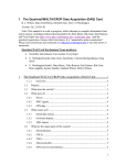
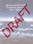
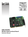
Technical Information Manual Revision n. 2 18 May 2010 MOD. FW1495SC V1495 FPGA SCALER FIRMWARE NPO: 00117/09:FWSCL.MUTx/02 CAEN Tools for Discovery n V1495scaler - Reference Guide Revision 2 CAEN will repair or replace any product within the guarantee period if the Guarantor declares that the product is defective due to workmanship or materials and has not been caused by mishandling, negligence on behalf of the User, accident or any abnormal conditions or operations. CAEN declines all responsibility for damages or injuries caused by an improper use of the Modules due to negligence on behalf of the User. It is strongly recommended to read thoroughly the CAEN User's Manual before any kind of operation. CAEN reserves the right to change partially or entirely the contents of this Manual at any time and without giving any notice. 2 CAEN Tools for Discovery n V1495scaler - Reference Guide Revision 2 Index 1 Functional Description............................................................................................4 2 Registers and VME interface ..................................................................................6 2.1 2.2 2.3 Register Description ........................................................................................................................ 6 Event Data Format .......................................................................................................................... 8 Firmware upgrade ........................................................................................................................... 8 List of Figures Fig. 1.1: Block Diagram................................................................................................................................................................... 4 List of Tables Tab. 2.1: Register Map..................................................................................................................................................................... 6 3 CAEN n Tools for Discovery V1495scaler - Reference Guide Revision 2 1 Functional Description FW1495SC is a FPGA firmware for CAEN V1495 model that allows to use the Mod. V1495 as a Multievent latching scaler housing up to 128 independent counting channels. Each channel has 32 bit counting depth and accepts LVDS/ECL/PECL differential inputs; the maximum input frequency is 250 MHz. The standard version of the board houses 64 input channels on two P50E-068-P1-SR1-TG connectors; in order to implement 96 or 128 channels it is necessary to plug the Mod. A395A expansion boards into the D and/or E slot. A Multievent latching Scaler with NIM/TTL input signals is achievable using the Mod. A395D expansion boards (8 NIM/TTL input channels on each A395D). USER FPGA TRIGGER CNTRES TEST INHIBIT G1 WRITE EVENT BUILDER G1 MODE CH. ENABLE MASK ENABLE AUTORESET G0 EXT TRIGGER SW TRIGGER ENABLE EXT. TRG PERIODIC TRIGGER GENERATOR VME FIFO (MEB) LATCH VME INTERFACE 32bit COUNTER RESET LOCAL BUS INTERFACE X 128 INPUTS ENABLE PER. TRG DWELL TIME Fig. 1.1: Block Diagram Each channel counts on the input signals leading edge; as a trigger arrives, all counters are latched simultaneously. This operation takes place independently from the counting that can continue unaffected; thanks to synchronization technique the readout value is always significant, even if the counter changes its value when is readout. After the trigger has arrived and the latch are loaded, the FPGA reads the latches and writes the enabled channels values into the FIFO memory (Multi Event Buffer) with a Header and an optional Trigger Time Tag, thus making an Event, that can be readout via VME. Once the event is written, the Scaler can accept another trigger even if the previous event is not readout yet, as long as the FIFO memory has enough space left for other data. The trigger signal can be either fed to the G0 connector (NIM or TTL) or internally generated by the FPGA, with a certain trigger period (DWELL TIME), from 1µs to 4000 s with 1 µs step. The trigger can also be sent via VME, by a write access to a certain register. The counters value can be also read via VME on the fly, independently from the counting, the trigger and the relevant event recording. The G1 connector can be used in three ways: counting inhibit test signal in order to allow all channels counting in parallel counters reset 4 CAEN Tools for Discovery n V1495scaler - Reference Guide Revision 2 The counters reset can be also asserted every time the trigger is sent (auto-reset option); in this way, the read values represent the counting value between two triggers instead of the absolute counting value from the beginning. The counters can also be reset via VME command (see § 2.1). 5 CAEN Tools for Discovery n V1495scaler - Reference Guide Revision 2 2 Registers and VME interface All the module’s registers can be accessed via D32 VME mode, with either A32 or A24 address in any mode (USER/SUPERVISOR, DATA/PROGRAM, CR/CSR, etc…). The data space (MEB) readout can be done either via D32 single cycle or via Block Transfer (32bit BLT). The following table reports the FPGA USER address offsets, to be added to the module’s base address; the FPGA VME address offsets are the same as reported in the V1495 User’s Manual. Register Address MEB 0x0000 (*) Type Description R Multi Event Buffer ACQ_CTRL 0x1000 R/W Control Register ACQ_CTRL_SET 0x1004 R/W Control Register BitSet ACQ_CTRL_CLR 0x1008 R/W FWREV 0x100C R Control Register BitClear Firmware Revision STATUS 0x1010 R Status Register COMMANDS 0x1014 W Commands Register CHEN_A 0x1020 R/W Channel Enable Mask for the group A CHEN_B 0x1024 R/W Channel Enable Mask for the group B CHEN_D 0x1028 R/W Channel Enable Mask for the group D CHEN_E 0x102C R/W Channel Enable Mask for the group E DWELL_TIME 0x1030 R/W Dwell Time (period of the internal trigger) COUNTERS_A 0x1100 – 0x117C R Direct read access to the counters of the group A COUNTERS_B 0x1180 – 0x11FC R Direct read access to the counters of the group B COUNTERS_D 0x1200 – 0x127C R Direct read access to the counters of the group D COUNTERS_E 0x1280 – 0x12FC R Direct read access to the counters of the group E (*) any address between 0x0000 and 0xFFFC is mapped onto the MEB. Tab. 2.1: Register Map 2.1 Register Description ACQ_CTRL address 0x1000, 0x1004, 0x1008, R/W There are three ways to access this register; by writing to address 0x1000: the value is directly written to the register 0x1004: bits written to 1 are set; bits written to 0 remain unchanged 0x1008: bits written to 1 are reset; bits written to 0 remain unchanged bit name description [0] EN_EXTTRG 0 => External Trigger Disabled, 1 => External Trigger Enabled [1] EN_INTTRG 0 => Internal Trigger Disabled, 1 => Internal Trigger Enabled [2] G_PORT_TYPE 1 => G ports are TTL, 0 => G ports are NIM [3] [5:4] [6] AUTO_RESET 0 => AutoReset Disabled, 1 => the counters are reset with the trigger G1_MODE [00] => G1 is used as INHIBIT [01] => G1 is used to reset the counters [10] => G1 is used as TEST SIGNAL [11] => RESERVED EN_TIMETAG 0 => Time Tag not reported in the event data, 1 => Time Tag reported in the event data FWREV address 0x100C, R only This read-only register reports the FPGA USER firmware revision with the following format (32bit): 6 CAEN Tools for Discovery n V1495scaler - Reference Guide Revision 2 YMDDMMmm (each letter corresponds to one nibble) Y = year (9 stands for 2009) M = month (1 =JAN, C = DEC) DD = day (decimal: ‘12’ stands for, not for 18) MM = major number = 0x80 (128 decimal, code corresponding to Scaler) mm = minor number (example: if mm = 2, version is 128.2) STATUS address 0x1010, R only bit name description [0] MEB FULL when 1, the MEB is full and no more trigger can be accepted until the MEB is read and there is enough space to write an event COMMANDS address 0x1014, W only A write access to this register allows the FPGA to execute one or more command; bit must be set to one in order to perform the corresponding function. bit name description [0] SWTRG Generates a software trigger (not maskable) [1] SWCNTRES Reset to 0 all counters [2] SWCLR Clear MEB [4] BDRESET Board reset CHEN_X address 0x1020, 0x1024, 0x1028, 0x102C R/W This register allows to enable the channels of A (0x1020), B (0x1024), D (0x1028) and E (0x102C) connectors; each register’s 32bit correspond to the relevant channel on the connector (1 = ch enabled). DWELL_TIME address 0x1030, R/W This register allows to set the internal trigger period: TTRG = N * 1µs With N = register value (32 bit); in order to use the internal trigger it is also necessary to enable by setting bit 1 of the Control Register. COUNTERS_X address from 0x1100 to 0x12FC, R only A read access to one of these addresses allows to read “on the fly” the value of the corresponding counter. The address of channel N is given by 0x1100 + N * 4. 7 CAEN Tools for Discovery n V1495scaler - Reference Guide Revision 2 2.2 Event Data Format One event’s data are organized as shown by the following figure: 31 30 29 28 27 26 25 24 23 22 21 20 19 18 17 16 15 14 13 12 11 10 9 8 EVENT COUNTER 7 6 5 4 3 2 1 0 EVENT SIZE (num. of words) TRIGGER TIME TAG COUNTERS (all enabled channels) 0 = No Time Tag 1 = Time Tag Present The Trigger Time Tag is optional (bit 6 of control register); if enabled, it represents the arrival time of the trigger (µs) from the latest board reset. Counters value are in sequential order. Bit 31 allows to either have (1) or have not (0), the Trigger Time Tag written. 2.3 Firmware upgrade It is possible to upgrade the board firmware via VME, by writing the Flash: for this purpose, download the software package and the CVUpgrade tool, both available at: http://www.caen.it/nuclear/product.php?mod=V1495 The instructions are explained by the README text file included in the CVUpgrade folder. 8