1
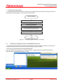
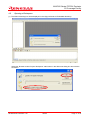
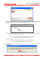
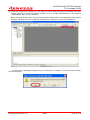
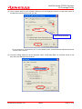
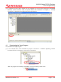
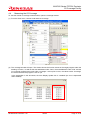
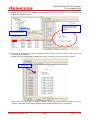
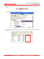
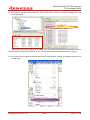
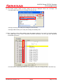
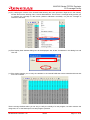
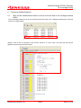
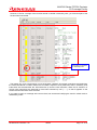
Application Note
M16C/60 Series PC7501 Emulator
C0 Coverage Facility
Summary
The full-spec emulator PC7501 for the M16C/60 series incorporates the C0 coverage facility. This
document explains how to use the C0 coverage facility while using the PC7501 emulator.
Explained in this document is for the case where the user system incorporating an M16C/60 series
microcomputer and the PC7501 emulator are used in combination. The content of this document may be
used in common for even a different target microcomputer providing it is one of the M16C/60 series
microcomputers.
Table of Contents
1.
Overview ........................................................................................................................................... 2
2.
Facilities Used ................................................................................................................................... 2
3.
3.1
3.2
3.3
Preparing the Software ..................................................................................................................... 2
Getting Started .................................................................................................................................. 2
Installing the Software Supplied with the PC7501 Emulator............................................................. 2
Auto Update Utility............................................................................................................................. 2
4.
4.1
4.2
4.3
4.4
Operational Description..................................................................................................................... 3
Starting the High-performance Embedded Workshop ...................................................................... 3
Opening a Workspace....................................................................................................................... 4
Downloading the Target Program ..................................................................................................... 8
Measuring the C0 Coverage ............................................................................................................. 9
5. Frequently Asked Questions ........................................................................................................... 18
5.1 Why do the measurement result in source units and that in the coverage window differ?............. 18
6.
Related Documents......................................................................................................................... 20
REJ06J0070-0100/Rev.1.00
2009.2
Page 1 of 22
M16C/60 Series PC7501 Emulator
C0 Coverage Facility
1.
Overview
The coverage facility refers to the one that measures the extent of a test covered. The coverage rate of a
test program measured while it was run is used to determine the validity of the test program. The coverage
facility comes in several types such as C0 coverage and C1 coverage. Incorporated in the PC7501 is the C0
coverage. Also known as instruction coverage, the C0 coverage allows measuring the coverage of whether
instructions were executed. On the other hand, the C1 coverage, also referred to as branch coverage, allows
measuring the coverage of whether a branch occurred on true or false side of a conditional branch
instruction.
The PC7501 can not only display the result of a C0 coverage measurement in the C0 coverage window,
but also permits you to verify instruction execution or non-execution in source line units using the editor
window columns, as well as verify instruction execution or non-execution in address units in the memory
window. The coverage measurement area can be any area comprised of 1 to 32 blocks (up to 8 Mbytes)
beginning with the 256-kbyte boundary. There is another thing to be noted for the PC7501’s C0 coverage
facility that its measurement result includes prefetches.
2.
Facilities Used
In this document, the method of C0 coverage measurement is explained using the sample program
included in the CD-ROM supplied with the PC7501 emulator or a downloaded package from the Renesas
website.
The tool versions used are listed below.
M16C R8C PC7501 Emulator Debugger V.1.03 Release 00 for the M16C series
3.
Preparing the Software
3.1
Getting Started
Install the software included in the CD-ROM that is supplied with the PC7501 emulator.
The sample program (tutorial workspace) used in this document will be expanded in your PC.
The software included in the CD-ROM that is supplied with the PC7501 emulator may also be installed in a
PC that has had the High-performance Embedded Workshop already installed. In this case, part of the
dialogs displayed during the installation work will be omitted.
3.2
Installing the Software Supplied with the PC7501 Emulator
Execute M16cPc7501 Debugger.exe present in the CD-ROM supplied with the PC7501 emulator.
For details on how to install, see the PC7501 emulator setup guide published at the Renesas website.
During installation work, follow the instructions displayed on the screen. The installation procedure is omitted
here.
3.3
Auto Update Utility
If you’ve selected the auto update utility when installing the software, it is possible to confirm via the
Internet whether the latest version of each tool is available.
REJ06J0070-0100/Rev.1.00
2009.2
Page 2 of 22
M16C/60 Series PC7501 Emulator
C0 Coverage Facility
4.
Operational Description
This section describes the method for using the C0 coverage facility after starting the High-performance
Embedded Workshop (HEW). The procedure is shown below.
Start of operation
Starting the HEW
Opening a workspace
Downloading the target program
Measuring C0 coverage
End
Figure 4.1 Example Program Execution Procedure
4.1
Starting the High-performance Embedded Workshop
To begin with, first connect the PC7501 emulator that has the user system connected to it and the host
computer with USB cable, and check to see that everything is ready to debug.
Next, start the High-performance Embedded Workshop.
From All Programs on the Start menu, choose Renesas → High-performance Embedded Workshop →
High-performance Embedded Workshop, to start.
REJ06J0070-0100/Rev.1.00
2009.2
Page 3 of 22
M16C/60 Series PC7501 Emulator
C0 Coverage Facility
4.2
Opening a Workspace
(1) The Welcome! dialog box will be displayed in the High-performance Embedded Workshop.
Select the “Browse Another Project Workspace” radio button in the Welcome! dialog box and click the
OK button.
REJ06J0070-0100/Rev.1.00
2009.2
Page 4 of 22
M16C/60 Series PC7501 Emulator
C0 Coverage Facility
(2) The Open a Workspace dialog box will be displayed.
If the installation of the CD-ROM of this product is complete, the workspace “Tutorial.hws” is stored as
standard in the folder position shown below. Check folder positions in order while you locate. When the
workspace “Tutorial.hws” is found, specify it and click the Select button.
C:\WorkSpace\Tutorial\PC7501\M16C\Tutorial\Tutorial.hws
C:\WorkSpace
Tutorial
PC7501
M16C
Tutorial
Tutorial.hws
[Note] Depending on the software version used, it will occur that the above directory cannot be specified.
In such a case, select the directory given below.
<Directory in which the High-performance Embedded Workshop is installed>
\Tools\Renesas\DebugComp\Platform\E8\M16C\Tutorial
Examples of directory:
C:\hew3\Tools\Renesas\DebugComp\Platform\E8\M16C\Tutorial
C:\hew2\Tools\Renesas\DebugComp\Platform\E8\M16C\Tutorial
(3) If the workspace version is old, the dialog box shown below is displayed. To update it to a new version,
click the OK button.
REJ06J0070-0100/Rev.1.00
2009.2
Page 5 of 22
M16C/60 Series PC7501 Emulator
C0 Coverage Facility
(4) When the workspace is opened, you are ready to use the High-performance Embedded Workshop.
Change sessions to connect the PC7501 emulator. To do it, change “DefaultSession” in the toolbar to
“SessionM16C_R8C_PC7501_Emulator.”
Before changing sessions here, be sure that the interface select switch on the back panel of the PC7501
emulator main body is set to the USB side, and then turn the power for the PC7501 emulator on.
If a dialog box is displayed prompting for your confirmation of whether to save the previous session,
click the Yes button.
REJ06J0070-0100/Rev.1.00
2009.2
Page 6 of 22
M16C/60 Series PC7501 Emulator
C0 Coverage Facility
(5) The Init (M16C R8C PC7501 Emulator) dialog box will be displayed. Select the “USB” radio button on
the MCU tab of the dialog box and click OK.
Automatically selected
y If your emulator is connected via LPT or LAN instead of USB, visit the Renesas website and see the
PC7501 user’s manual.
(6) The MCU Setting dialog box will be displayed. Select “Single-Chip Mode” for Processor Mode on the
MCU tab of the dialog box and click OK.
REJ06J0070-0100/Rev.1.00
2009.2
Page 7 of 22
M16C/60 Series PC7501 Emulator
C0 Coverage Facility
(7) A connection of the PC7501 emulator will be completed, by which the High-performance Embedded
Workshop screen becomes ready to operate. When this connection is complete, a message
“Connected” is displayed on the Debug tab of the output window.
4.3
Downloading the Target Program
First, download the target program.
(1) In the example here, we’ll download the program “Tutorial.x30 - 00000000” appearing beneath
Download Modules in Workspace. Double-click it to download.
Execute
When the program is successfully downloaded, its icon is marked by a down arrow.
REJ06J0070-0100/Rev.1.00
2009.2
Page 8 of 22
M16C/60 Series PC7501 Emulator
C0 Coverage Facility
4.4
Measuring the C0 Coverage
To view the results of coverage measurements, open the coverage window.
(1) From the View menu, choose Code and then Coverage.
(2) The coverage window will open. The window shows the function names of the target program under the
heading “Function,” as well as the start addresses under “Start,” the end addresses under “End” and the
C0 coverage measurement result under “Coverage.” At this point in time, the values under “Coverage”
are 0.00% because the program is not run yet.
In the explanation in this document, the Auto Display Update icon is “enabled” (the icon is depressed
when enabled).
REJ06J0070-0100/Rev.1.00
2009.2
Page 9 of 22
M16C/60 Series PC7501 Emulator
C0 Coverage Facility
• Description of the icons
Source selection: Selects the source file for which the results of coverage measurements are
displayed.
When you select the Source Select icon, the Select Source Files dialog box is displayed, allowing
you to display only a selected source file in the coverage window.
the icon is depressed when enabled
Automatic display update: Automatically updates the displayed coverage measurement result when
the target program stops.
Display update: Updates the displayed coverage measurement result.
Initialization: Initializes the coverage measurement result.
REJ06J0070-0100/Rev.1.00
2009.2
Page 10 of 22
M16C/60 Series PC7501 Emulator
C0 Coverage Facility
(3) Double-click any function line displayed in the coverage window. The function you’ve selected will be
displayed in the editor window.
The selected function is
displayed in the editor
window.
Double-click any line.
(4) We’ll now try stopping the program immediately before a call to the sort function to see how the C0
coverage will be measured.
Double-click in the Address Match Breakpoint column at line No. 40 of the source file “Tutorial.c.”
Double-click
Since we’ve set the program to break immediately before the source address “F4276” of the sort
function is executed, the functions change and abort present ahead of it are not executed.
REJ06J0070-0100/Rev.1.00
2009.2
Page 11 of 22
M16C/60 Series PC7501 Emulator
C0 Coverage Facility
(5) Run the target program to measure the C0 coverage. Select the Run After Reset icon to run the
program.
The program can also be run from the Debug menu.
(6) While a C0 coverage measurement is in progress, the “Coverage” values in the coverage window are
shown as “– %.”
REJ06J0070-0100/Rev.1.00
2009.2
Page 12 of 22
M16C/60 Series PC7501 Emulator
C0 Coverage Facility
(7) The program will stop at the breakpoint, showing the result of the C0 coverage measurement in the
coverage window.
In this case, the function change to be called after the function sort and the function abort used for
interrupts were not executed. Therefore, as you can see, their measured values are shown as “0.00%.”
(8) The result of C0 coverage can also be verified in the editor window. Choose “Set Display Columns” from
the Edit menu.
REJ06J0070-0100/Rev.1.00
2009.2
Page 13 of 22
M16C/60 Series PC7501 Emulator
C0 Coverage Facility
(9) The Entire Column State of Editor dialog box will be displayed. Select the “Coverage” and
“Coverage-ASM” check boxes in the dialog box and click OK.
Coverage: Permits you to verify C0 coverage in C source units.
Coverage-ASM: Permits you to verify C0 coverage in assembly units.
(10) The “Coverage” column will be added in the editor window, allowing you to verify C0 coverage visually.
The yellow part of this column represents executed instructions, and the gray part represents
unexecuted instructions.
In mixed mode or disassembly mode too, it is possible to verify C0 coverage visually in the same way.
REJ06J0070-0100/Rev.1.00
2009.2
Page 14 of 22
M16C/60 Series PC7501 Emulator
C0 Coverage Facility
(11) What’s more, it is possible to verify C0 coverage visually in address units using the memory window.
Choose CPU and then Memory from the View menu.
(12) The Display Start Address dialog box will be displayed. Set “H’F4270” for Display Start Address in this
dialog box and click OK.
REJ06J0070-0100/Rev.1.00
2009.2
Page 15 of 22
M16C/60 Series PC7501 Emulator
C0 Coverage Facility
(13) The memory window will open. Right-click in the window and from the ensuing menu, choose Coverage
and then Enable.
(14) The memory window will be color-coded. Shown in the blue part are the executed instructions, and
those in the gray part are the unexecuted instructions.
REJ06J0070-0100/Rev.1.00
2009.2
Page 16 of 22
M16C/60 Series PC7501 Emulator
C0 Coverage Facility
(15) Try verifying the content of the internal RAM following the same procedure. Right-click in the memory
window and from the ensuing menu, choose Start Address. The PC7501’s coverage facility permits you
to measure the coverage of data areas (whether addresses accessed), not just the coverage of
instruction execution.
(16) The Display Start Address dialog box will be displayed. Set “H’400” for Address in this dialog box and
click OK.
(17) The window permits you to verify the variables in the internal RAM that were accessed and those that
were not accessed.
These coverage facilities allow you not only to verify the validity of a test program, but also measure the
usage rate, etc. of the RAM space in actual program operation.
REJ06J0070-0100/Rev.1.00
2009.2
Page 17 of 22
M16C/60 Series PC7501 Emulator
C0 Coverage Facility
5.
5.1
Frequently Asked Questions
Why do the measurement result in source units and that in the coverage window
differ?
Run the sample program once up until it ends and see the result of C0 coverage measurement. It will look
like the one shown below.
Taking a look at the C0 coverage of the function tutorial in C source units, you’ll find that the function
appears to have been executed in whole.
REJ06J0070-0100/Rev.1.00
2009.2
Page 18 of 22
M16C/60 Series PC7501 Emulator
C0 Coverage Facility
However, if the C0 coverage of the function tutorial is verified in assembly units, you’ll find that part of the
function was unexecuted.
Executed up until here
in assembly units
The reason why such a phenomenon occurs is because a prefetch is involved. Instructions are loaded into
the cache beforehand no matter whether the next data is required. Once prefetched, when in assembly units,
instructions are executed after the JEQ instruction up until the next instruction. When this is verified in C
source units, instructions are assumed to have been executed up until “j = –j,” so that it appears on the
surface that all instructions were executed.
If you want to verify C0 coverage at the source level, we recommend verifying the result in mixed mode or
disassembly mode.
REJ06J0070-0100/Rev.1.00
2009.2
Page 19 of 22
M16C/60 Series PC7501 Emulator
C0 Coverage Facility
6.
Related Documents
The PC7501 emulator and the HEW have numerous other convenient facilities and features not discussed
in this document. Detailed specifications, technical information, limitations and other useful information on
each product are described in the related documents listed below. Please see these manuals along with this
document.
[PC7501 emulator related documents]
• M16C R8C PC7501 Emulator Debugger User’s Manual (for the M16C/60, M16C/30, M16C/Tiny and
R8C/Tiny series)
• M16C R8C PC7501 Emulator Debugger Release Notes (for the M16C/60, M16C/30, M16C/Tiny and
R8C/Tiny series)
• PC7501 Setup Guide (M16C Family Emulator)
• PC7501 User’s Manual (M16C Family Emulator)
[High-performance Embedded Workshop related documents]
• High-performance Embedded Workshop User’s Manual
• High-performance Embedded Workshop Release Notes
[CPU related documents]
• M16C/60 Series Hardware Manual
• M16C/60, M16C/20, M16C/Tiny Series Software Manual
[M16C/60 series C compiler related documents]
• M3T-NC30WA C Compiler Guidebook (C compiler package for the R8C/Tiny, M16C/60, M16C/30,
M16C/20, M16C/10 and M16C/Tiny series)
• M3T-NC30WA Assembler User’s Manual (C compiler package for the R8C/Tiny, M16C/60, M16C/30,
M16C/20, M16C/10 and M16C/Tiny series)
To see more information on the PC7501 emulator, please visit the Renesas websites given below.
Japan site:
http://japan.renesas.com/pc7501
Global site:
http://www.renesas.com/pc7501
REJ06J0070-0100/Rev.1.00
2009.2
Page 20 of 22
M16C/60 Series PC7501 Emulator
C0 Coverage Facility
Home Page and Where to Contact for Support
Renesas Technology home page
http://www.renesas.com/
Where to contact
http://www.renesas.com/inquiry
Revision Record
Rev.
1.00
Issue date
2009.2.13
REJ06J0070-0100/Rev.1.00
Page
—
Contents of revision
Points
First edition issued
2009.2
Page 21 of 22
M16C/60 Series PC7501 Emulator
C0 Coverage Facility
© 2009. Renesas Technology Corp., All rights reserved.
REJ06J0070-0100/Rev.1.00
2009.2
Page 22 of 22