1
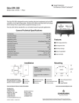
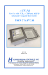
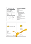
PRO-FINISHER Doc rev 012915 ‐ Patent Pending Copyright Engineering Innova on Mfg, LLC. 2014 Pro—Finisher Manufactured by Engineering Innovation Mfg, LLC Cedar Rapids, IA 52411 Phone: 319-294-2321 Email: [email protected] Call 319-294-2321 for Technical Support We warranty our product to be free from manufacturing defects for a period of 1 year from date of purchase. See last page for info to register and active your warranty. Doc rev 012915 ‐ Patent Pending Copyright Engineering Innova on Mfg, LLC. 2014 PRO-FINISHER—SM Specifica ons: Unit Dimensions: 27L x 16W x 13.875H (12 gallon water capacity) Cleaning tank: 13L x 12W x 8.25H Auto‐separator tank design Waste wax is skimmed off top of cleaning tank by water flow Waste wax is separated to minimize wax intrusion to pump. Waste wax automaƟcally drains off to removable drawer to be discarded External pump/plumbing for water circula on Water level maintained automa cally via reservoir tank Thermo‐ sta cally con‐ Doc rev 012915 ‐ Patent Pending Copyright Engineering Innova on Mfg, LLC. 2014 PRO-FINISHER—LG Specifica ons: Unit Dimensions: 45L x 19W x 17.86H (26 gallon water capacity) Cleaning tank: 22L x 16W x 11.75H Auto‐separator tank design Waste wax is skimmed off top of cleaning tank by water flow Waste wax is separated to minimize wax intrusion to pump. Waste wax automaƟcally drains off to removable drawer to be discarded External pump/plumbing for water circula on Water level maintained automa cally via reservoir tank Thermosta cally controlled water temperature Doc rev 012915 ‐ Patent Pending Copyright Engineering Innova on Mfg, LLC. 2014 NOTE BEFORE SETUP Important: Before turning on the Pro-FINISHER, be certain that the tank is full of water. Applying electrical current to the heating element while not submerged in water will destroy the element and void warranty. SETUP 1) Place tank on level countertop height surface able to support 300 lbs. 2) Plug pump into electrical outlet on side of tank. 3) Fill all compartments with water to level of rear divider. NOTE—due to evaporation, it is necessary to add water periodically, The right tank acts as a reservoir and is designed to fluctuate in depth as large parts are introduced to the left tank displacing the water. Turn the unit on (main switch) aŌer filling with water. (see last page for fill level) Red light will indicate when unit is “on”. Orange light indicates that the tank is heaƟng and will go out once operaƟng temperature is met, approximately 148 degrees . Turn on Pump during processing—do not leave the pump on conƟnuously. The removable basket of the cleaning tank is designed to be lifted out in order to retrieve parts. It may be placed on top of the tank as shown. Doc rev 012915 ‐ Patent Pending Copyright Engineering Innova on Mfg, LLC. 2014 OPERATIONS—CLEANING PROTOTYPE PARTS Recommended tools: Paper towels Tongs (small and large) Fish tank dip net for handling smaller parts. Doc rev 012915 ‐ Patent Pending Copyright Engineering Innova on Mfg, LLC. 2014 Remove support wax from part by manual scraping where possible. Using Tongs, slowly immerse part in main tank chamber. CAUTION—WATER is EXTREMLY HOT! DO NOT DROP PARTS IN as it may cause splashing of hot water leading onto user or surrounding work area. After a few seconds you will notice wax melt, float up, and be carried to the second chamber. You may speed the process slightly by “stirring” the part gently using the tongs. Doc rev 012915 ‐ Patent Pending Copyright Engineering Innova on Mfg, LLC. 2014 NEEDLE JET OPERATION A four inch needle jet hose assembly has been added to aid in flushing wax from small holes and internal cavities. The unit is shipped with a cap on the end of the hose which prevents flow through the hose when not in use with the needle. The cap and the needle are connected or disconnected by turning 1/4 turn clockwise or counter clockwise respectively. NOTE—Slightly closing the ball valve on the main tank will increase the pressure delivered to the needle jet. It is not recommended to close the valve completely. After it appears that there is little or no wax surfacing, remove the part from the tank and dry with paper towels. Re-dip as needed. The part shown was cleaned in approximately 9 minutes. NOTES ON OPERATIONS: For smaller parts, you may want to use a fish tank dip net to prevent losing them in the tank. See image below. Doc rev 012915 ‐ Patent Pending Copyright Engineering Innova on Mfg, LLC. 2014 NOTES ON OPERATIONS (cont’d): You will notice the wax accumulate in the skimmer tank. As more wax enters this tank, the wax level will rise until wax begins to flow down the stand pipe tube. Approximately 3 inches of wax will accumulate before wax begins to drain down the standpipe. Periodically you must remove the drawer from the unit and discard the accumulated wax. Exercise caution as it may be HOT. Alternatively, your unit may be placed over a hole in the counter or cart support shelf, allowing the wax to fall directly into a waste container. Always discard the waste wax material according to instructions provided by your rapid prototype machine manufacturer. Doc rev 012915 ‐ Patent Pending Copyright Engineering Innova on Mfg, LLC. 2014 SHUTTING DOWN THE SYSTEM To shut the finisher down for any reason, take the following steps. 1.) Remove wax from the separating chamber before draining the tank. Block the exit path of the water at the rear of the rear divider temporarily causing the water level to rise under the wax, forcing it to drain. A 3x12 piece of cardboard held against divider works well. Unblock the flow just before water begins to drain down the tube. Cloudy water can be expected with extended use and is not a problem, nor will it the slow the cleaning process. 2.) Close the ball valves and disconnect the hoses at the pump and direct them into a bucket and open the ball valve to drain the tank. NOTE: After main tank and reservoir tanks are empty, remove the rubber stopper from the bottom rear corner of the rear divider allowing separator to drain. RECOVERING from inadvertent shutdown If your unit loses power for a long enough time, the wax in the separator will solidify. Before turning the unit on, switch off the pump to prevent water overflowing the separator drain. Remove some or all of the solidified wax by carving out or drilling holes in it to create a total area opening of at least 2 square inches. This will allow the water to flow through the separator. As the water heats up, the remaining wax will melt returning the system back to normal operation. You can begin cleaning parts immediately, as wax will build up and over any solidified wax, while water will run out through the separating dividers. Doc rev 012915 ‐ Patent Pending Copyright Engineering Innova on Mfg, LLC. 2014 TIPS FOR BEST OPERATION Open both ball valves to allow water levels to equalize. Fill to a level just below the right hand divider. This will allow for processing most common sized prototype parts as the reservoir tank will rise and fall to accommodate the part while maintaining the “full” level of the main tank. See image to right. Due to evaporation, additional water will need to be added occasionally. While in operation, the right tank should be at least 3” deep. It is best to regulate the water flow to a slow rate. !!! Ideally, the water should “wrap” over the divider, not pour. This will minimize mixing of the wax and water. It also helps minimize heat loss due to stirring action. The ball valve on the inlet to the main tank should be closed to about half of its travel position. See image to right. Doc rev 012915 ‐ Patent Pending Copyright Engineering Innova on Mfg, LLC. 2014 Registration of your unit Register your product to activate the warranty and be included in any service bulletins on components or operational improvements of the unit. By email: Email to [email protected] the following; Company Name Company Contact person name Phone number of contact person Date of Purchase (enter here for your records)_____________ Serial number of unit EI-######-# _______________________ (format is EI followed by characters) (found on rear return flange—top right of rear of unit.) By phone: Call Engineering Innovation at 319-294-2321. Doc rev 012915 ‐ Patent Pending Copyright Engineering Innova on Mfg, LLC. 2014 Doc rev 012915 ‐ Patent Pending Copyright Engineering Innova on Mfg, LLC. 2014