1
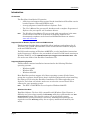
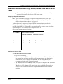
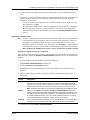
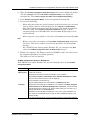
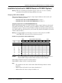
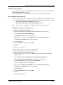
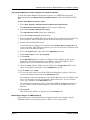
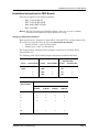
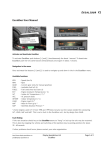
Installation and Troubleshooting
Welcome to Excalibur Systems suite of boards, cards and modules. This document
describes Excalibur hardware and software installation, and troubleshooting and
support information.
Introduction ...................................................................................................................... 2
CD Contents ..........................................................................................................................
Supported Carrier Boards, Express Cards and PCMCIA Cards............................................
Supported Operating Systems...............................................................................................
Maximum Modules per Carrier Board ....................................................................................
2
2
2
3
Installation Instructions for PCI[e] Boards, Express Cards and PCMCIA Cards ....... 4
Assigning a Unique ID to the Board.......................................................................................
Installing the Board or Card ...................................................................................................
Verifying Board/Card Installation ...........................................................................................
Installing the Software Tools..................................................................................................
Running a Test Program........................................................................................................
Multiple Board Support for PCI[e] Boards, Express Cards and PCMCIA Cards....................
4
4
5
6
8
8
Installation Instructions for VME/VXI Boards on PCI-MXI-2 Systems......................... 9
Assigning a Device ID to the Board ....................................................................................... 9
Installing the Board .............................................................................................................. 10
Installing the Software Tools................................................................................................ 11
Verifying VME/VXI User Window Size ................................................................................. 11
Viewing Global Module Information Registers (for Windows 2000/XP) ............................... 12
Multiple Board Support for VME/VXI Boards ....................................................................... 12
Installation Instructions for PMC Boards .................................................................... 13
Assigning a Unique ID to the Board..................................................................................... 13
Installing a PMC Board on a [c]PCI Carrier Board............................................................... 14
Installing a PMC Board on a VME Carrier Board under VxWorks ....................................... 14
Troubleshooting............................................................................................................. 15
Software Installation Issues ................................................................................................. 15
General Troubleshooting ..................................................................................................... 16
Contacting Technical Support.............................................................................................. 16
Installation and Troubleshooting
page 1
Introduction
Introduction
CD Contents
The Excalibur Installation CD contains:
•
All drivers and support files required for the installation of Excalibur carrier
boards, Express cards and PCMCIA cards.
•
A setup program to install Excalibur's Software Tools.
•
The User’s Manual for your specific hardware and a complete Programmer’s
Reference for your specific set of software drivers.
Note:
The Excalibur Installation CD you received with your package is the most
recent release of the CD as of the date of shipping. Software and
documentation updates can be found and downloaded from our website:
www.mil-1553.com.
Supported Carrier Boards, Express Cards and PCMCIA Cards
This document describes how to install Excalibur hardware and software for all
PCI, PCIe, cPCI, VME, VXI and PMC carrier boards and their modules; Express
cards and PCMCIA cards.
For ISA boards running on Windows 9x/ME/NT4, see the installation instructions
in the Programmer’s Reference for your module or board. For ISA boards running on
Windows 2000/XP, see the ISA KernelDriver support for Windows 2000.txt
file on the root folder of the Excalibur Installation CD.
Supported Operating Systems
This document contains installation instructions for the following Windows
operating systems:
•
Windows 9x/ME
•
Windows NT4
•
Windows 2000/XP
Most Excalibur products support all of these operating systems. Each of these
groups has a separate kernel driver that is installed automatically when installing
the Software Tools using the Excalibur Installation CD. When upgrading your
Software Tools from our website, make sure to select the correct kernel driver
software for your operating system.
Note:
The EXC-1553PCMCIA/Px card requires Windows 2000/XP.
Windows Vista Note
Excalibur Software Tools are fully compatible with Windows Vista. However, a
difficulty may arise when running the ExcConfig utility due to Microsoft's new User
Account Control feature. This feature requires you to specifically request
administrative privileges whenever necessary. Administrative privileges are
required to run the ExcConfig utility due to registry modifications made by the
utility.
page 2
Excalibur Systems
Introduction
Therefore, you can no longer run ExcConfig by double-clicking on its icon, nor can you
run ExcConfig by choosing it from the Start menu. Attempting either of these options
will result in an error message. Instead, right-click on the icon (or menu item) and
choose Run as administrator.
Maximum Modules per Carrier Board
The Software Tools support the use of multiple modules per carrier board, and
multiple carrier boards simultaneously. The following table lists the maximum
modules per carrier board:
EXC-4000PCI[e],
EXC-4000cPCI
EXC-4000VME/VXI
EXC-2000PCI
M4K1553Px
4
8
N/A
M4KMMSI
4
8
N/A
M4K1553MCH
4
8
N/A
M4K429RTx
4
8
2
M4KDiscrete
4
8
2
M4KSerial
4
8
2
M4KH009
2
4
N/A
M4KCAN
4
8
2
M4K708
4
8
2
Note:
•
•
•
The EXC-4000P104plus carrier board supports two removable M4K
modules, one built-in M4K429RTx module and two built-in M4K1553Px
modules.
The EXC-1553ccVME/Px board comes with up to 16 built-in M4K1553Px
modules.
For information on multiple board support, see Multiple Board Support for PCI[e]
Boards, Express Cards and PCMCIA Cards on page 8 and Multiple Board Support for
VME/VXI Boards on page 12.
Installation and Troubleshooting
page 3
Installation Instructions for PCI[e] Boards, Express Cards and PCMCIA Cards
Installation Instructions for PCI[e] Boards, Express Cards and PCMCIA
Cards
Warning:
Whenever handling an Excalibur board, make sure to wear a suitably
grounded electrostatic discharge (ESD) wrist strap.
Assigning a Unique ID to the Board
Note:
This section does not apply to Express cards and PCMCIA cards. For
Express cards and PCMCIA cards, instead of assigning a Unique ID use the
Socket Number where the card is inserted.
Each board must be assigned a Unique ID. This information is stored in the
Windows System Registry and is used when accessing the board.
Set DIP switch SW1 to a Unique ID by setting the switch contacts open (or off) to
represent logic ‘1’ and closed (or on) to represent logic ‘0’.
Set the DIP switch contacts as follows:
For Board ID #:
Set the Contacts as Follows:
Contact #1
Contact #2
Contact #3
Contact #4
0
0
0
0
0
1
0
0
0
1
2
0
0
1
0
3
0
0
1
1
1
1
1
1
•
•
•
15
Installing the Board or Card
To install an Excalibur carrier board or card:
1. Do one of the following:
•
For carrier boards: Make sure the computer is turned off. Insert the board
into one of the available slots. (For more information see the Installation
section in the User’s Manual for the board you are using.) Start your
computer and wait until Windows boots up.
•
For Express cards and PCMCIA cards: Turn on the computer and wait until
the operating system boots up. Insert the card into an appropriate slot.
When the card is almost all the way in the slot, push firmly but gently, to
ensure a firm connection with the computer. Do not force the card into
position.
page 4
Excalibur Systems
Installation Instructions for PCI[e] Boards, Express Cards and PCMCIA Cards
2. For Windows operating systems that support "Plug and Play" (9x/ME/2000/XP),
a wizard is displayed to help you install your new hardware. When the wizard
asks for a disk or CD containing the driver for the board, select the root folder of
the CD. The operating system will find the correct file, and install the kernel
driver.
Note:
If the EXC-1553ExCARD/Px is not automatically recognized by Windows
when plugged into an ExpressCard slot, open the Windows Device Manager,
right-click on any device and select Scan for hardware changes.
Note:
It is recommended to always insert the EXC-1553ExCARD/Px when the
computer is off.
Note:
Windows NT does not automatically recognize new hardware. For Windows
NT, continue with Installing the Software Tools on page 6, reboot your computer,
then run a test program (see Running a Test Program on page 8).
3. If the wizard is not displayed, do the following:
•
For Windows 9x/ME: Right-click My Computer and select Properties. Click the
Device Manager tab then double-click Excalibur PCI or PCMCIA Cards. Double-click
the Excalibur PCI or PCMCIA Cards, click the Driver tab, then click Update Driver.
Follow the Update Device Driver Wizard.
•
For Windows 2000/XP: Right-click My Computer and select Properties. Click the
Hardware tab, then click Device Manager. Double-click Excalibur PCI or PCMCIA
Cards. Right-click the Excalibur PCI or PCMCIA Cards and select Update Driver.
Follow the Hardware Update Wizard.
4. Insert the Excalibur Installation CD in the CD drive and follow the wizard to
install the new hardware.
The board installation is complete.
5. If you are prompted to reboot your computer, reboot now.
Verifying Board/Card Installation
To verify board/card installation:
Note:
The following instructions do not apply to Windows NT. For Windows NT, to
verify installation install the software (see Installing the Software Tools on
page 6), reboot your computer, then run a test program (see Running a Test
Program on page 8).
1. Make sure that the Excalibur board/card is in place in the computer.
2. Right-click My Computer and select Properties.
The System Properties dialog box is displayed.
3. Do one of the following:
•
For Windows 9x/ME: In the System Properties dialog box, click the Device
Manager tab.
•
For Windows 2000/XP: In the System Properties dialog box, click the Hardware
tab, then click Device Manager.
4. Double-click Excalibur PCI or PCMCIA Cards.
Installation and Troubleshooting
page 5
Installation Instructions for PCI[e] Boards, Express Cards and PCMCIA Cards
5. Verify that the Excalibur board/card is listed next to a gray diamond-shaped
icon.
If you see a yellow exclamation point (!) superimposed on the gray diamond or a
yellow question mark (?), this indicates that the board/card is not properly
installed. In this case:
•
Verify that there is enough memory available in the system. If not, free up
more memory or IRQs.
•
For Windows 9x/ME: Verify that the computer is Plug and Play compatible.
Many computers claim to be “Plug and Play” but are not fully compatible
with the Plug and Play specification. See step 3 of Installing the Board or Card on
page 4.
Installing the Software Tools
Note:
If there is already a previous version of Software Tools for the same module/
card installed on the computer, the new version will overwrite it. However,
the software installation works best on a system that does not have any
Excalibur products installed on it. Therefore, it is strongly recommended to
uninstall the previous version before installing the new version by selecting
Start | Control Panel | Add/Remove Programs or Start | Control Panel | Uninstall a program.
To install the Software Tools for your module/card:
If you want to save the earlier version, you can choose to install the new version in a
different folder when the Excalibur InstallShield Wizard prompts you for an installation
location.
1. Insert the Excalibur Installation CD in the CD drive.
The Excalibur InstallShield Wizard is displayed.
2. Click the Software Tools Installation button.
3. Follow the on-screen instructions to select the software that matches your
product.
4. When an Excalibur product is already installed, the following options are
displayed:
Option
Description
Modify
When you select Modify, the Excalibur InstallShield Wizard detects all Excalibur
software on your computer and then allows you to install/uninstall additional products
from the system. Use this option to install new products, or to uninstall products. Select
the items that should remain on the system. Deselect those that you want to remove.
Note: The Modify option detects only those items installed using this installation program.
Repair
When you select Repair, the installation Excalibur InstallShield Wizard detects all
Excalibur products that are installed, and reinstalls them without any user interaction. Use
this option to repair a possibly faulty installation, or to install the latest released version of
all currently installed products on top of the currently installed versions on your system.
This is especially useful for installing an updated version of the software.
Remove
When an Excalibur product is installed, you can select Remove to remove all unmodified
Excalibur files from your system. New and modified files remain, and are unaffected.
5. Continue with the Excalibur InstallShield Wizard.
page 6
Excalibur Systems
Installation Instructions for PCI[e] Boards, Express Cards and PCMCIA Cards
6. When the Excalibur Configuration Utility (ExcConfig) main screen is displayed, doubleclick the Card Type field. (If the Excalibur Configuration Utility is not displayed
automatically, select Start | Programs | Excalibur | ExcConfig Board Setup Utility.)
7. In the Excalibur Configuration Wizard, select the appropriate board/card.
8. Do one of the following:
•
When using more than one carrier board (or card) of the same type, you must
select a unique value for each board/card in the Unique ID or Socket Number
field. This number must match the DIP switches of the board or the Socket
Number of card. (See Assigning a Unique ID to the Board on page 4.) In the
remaining fields, leave the Auto values and click Save. Repeat steps 6–8 for
each board/card.
•
When using one carrier board or card, leave all the Auto values and click Save.
Note:
•
•
Make a note of the row number in the Excalibur Configuration Utility assigned to
the device. This device number is used as the parameter for the Init_Module
function.
For a PCMCIA card running under Windows NT, you cannot use the Auto
values. See PCMCIA Configuration Values for Windows NT on page 7.
9. Reboot your computer. For Express cards and PCMCIA cards, leave the card in
the computer throughout the reboot operation.
The Software Tools are installed.
PCMCIA Configuration Values for Windows NT
For PCMCIA cards under Windows NT, use the following values in the Excalibur
Configuration Wizard:
Name of Field
Enter the Value
Type
Select the appropriate PCMCIA card.
Memory base
A 72K area of memory
To determine which memory areas are available on your computer:
Select Start | Programs | Administrative Tools | Windows NT Diagnostics | Memory. The memory areas currently in use are displayed.
Find a 72K block of unused memory.
Type the starting address of the unused block in the Memory base field.
Interrupts
To determine which interrupts are available on your computer, select Start | Programs
| Administrative Tools | Windows NT Diagnostics | Resources. You will see which
Interrupt Numbers are currently in use. Find a number that is not in use (often 5 or 7),
and type that number into the Interrupt field.
Sometimes an Interrupt (IRQ) is not listed as “in use”, but is in fact unavailable. You
may need to try several IRQs before you find one that is available and allows you to
continue working.
If you are not using interrupts, it is recommended to leave the Interrupt field undefined.
Installation and Troubleshooting
page 7
Installation Instructions for PCI[e] Boards, Express Cards and PCMCIA Cards
Running a Test Program
The Software Tools for each module/card includes various demo programs to verify
that the specific module/card is operating properly. The source code is provided with
the demo programs as a guide to develop your own applications using the Software
Tools for the module/card.
To run a test program:
•
Select Start | Programs | [Module/Card Name] | [Demo Program Icon].
Multiple Board Support for PCI[e] Boards, Express Cards and PCMCIA Cards
You can use any combination of up to 16 PCIe, PCI or cPCI boards simultaneously.
When using more than one Excalibur board on a single machine, you must:
1. Assign a Unique ID to each board using DIP switch SW1 on the PCI[e] board.
See Assigning a Unique ID to the Board on page 4. (This step is not applicable to
Express cards or PCMCIA cards.)
2. After installing the board, use the ExcConfig utility to assign a device number to
the board, by associating a device number with the board’s Unique ID or Socket
Number. (The Socket Number is the slot number in which the Express card or
PCMCIA card is located.)
For each board, enter the appropriate values in the ExcConfig screen:
Name of Field
Enter the Value
Type
Select EXC-4000PCI from the
drop-down list.
Unique ID
Enter the Unique ID previously
assigned to the board. See
Assigning a Unique ID to the
Board on page 4.
Memory
Accept the default value.
Interrupt Setup
Accept the default value.
I/O ports
Accept the default value.
Note:
•
•
page 8
The ExcConfig utility is not for use with VME/VXI boards. For multiple VME/
VXI boards, see Multiple Board Support for VME/VXI Boards on page 12.
To use more than four boards, you must be using Software Tools released on
or after September 2007.
Excalibur Systems
Installation Instructions for VME/VXI Boards on PCI-MXI-2 Systems
Installation Instructions for VME/VXI Boards on PCI-MXI-2 Systems
Warning:
Whenever handling an Excalibur board, make sure to wear a suitably
grounded electrostatic discharge (ESD) wrist strap.
Assigning a Device ID to the Board
This section discusses how to assign a unique logical address to the board, and
contains the following sections:
•
Assigning a Device ID to an EXC-4000VME/VXI Board on page 9
•
Assigning a Device ID to an EXC-1553ccVME/Px Board on page 10
Assigning a Device ID to an EXC-4000VME/VXI Board
Before installing the board, you must assign a unique logical address to the board
using DIP switch SW1. The board requires a 1MB area of memory (within A24 or
A32 memory space). Choose a logical address (within A16 memory space) that does
not conflict with any other devices in your system. By default, the board is set to the
address 80H (128 Dec.).
Warning:
If a logical address is already in use and it is also used for the EXC4000VME/VXI, the board will not function properly.
Examples of Logical Address Switch (SW1) Settings:
MSB
Logical Address Switch (SW1)
LSB
‘1’
‘1’
1
2
3
4
5
6
7
8
A15
A14
A13
A12
A11
A10
A9
A8
A7
A6
Logical Address
Hex
Switch Settings
Dec
1
1
0
0
0
0
0
0
0
1
20
32
0
0
1
0
0
0
0
0
80
128
1
0
0
0
0
0
0
0
81
129
1
0
0
0
0
0
0
1
C0
192
1
1
0
0
0
0
0
0
FF
255
1
1
1
1
1
1
1
1
Example:
For a logical address of C0 (H) [=A16 Address F000 (H)], set position 1
and 2 to OFF or Open and all other switches to ON or Closed.
Switch ON or Closed = logic 0 at switch position
Switch OFF or Open = logic 1 at switch position
Note:
•
•
•
The numbers in the above table under Switch Settings indicate switch
positions.
Address lines A15 and A14 are always decoded as ‘1’.
Address lines A5–A0 are always decoded as ‘0’.
Installation and Troubleshooting
page 9
Installation Instructions for VME/VXI Boards on PCI-MXI-2 Systems
Assigning a Device ID to an EXC-1553ccVME/Px Board
Before installing the board, you must assign a unique logical address to the board
using jumpers JP1–JP8. The board requires a 2MB area of memory (within A24 or
A32 memory space). Choose a logical address (within A16 memory space) that does
not conflict with any other devices in your system. By default, the board is set to the
address 80H (128 Dec.).
Warning:
If a logical address is already in use and it is also used for the EXC1553ccVME/Px, the board will not function properly.
Examples of Logical Address Jumper (JP1–JP8) Settings:
MSB
Logical Address Jumpers (JP1–JP8)
‘1’
‘1’
JP1
JP2
JP3
A15
A14
A13
A12
A11
Logical Address
Hex
LSB
JP4
JP5
JP6
JP7
JP8
A10
A9
A8
A7
A6
Jumper Settings
Dec
1
1
0
0
0
0
0
0
0
1
20
32
0
0
1
0
0
0
0
0
80
128
1
0
0
0
0
0
0
0
81
129
1
0
0
0
0
0
0
1
C0
192
1
1
0
0
0
0
0
0
FF
255
1
1
1
1
1
1
1
1
Example:
For a logical address of C0 (H) [=A16 Address F000 (H)], short jumpers
JP3–JP8, and do not short jumpers JP1 and JP2.
Jumper shorted = logic 0
Jumper open = logic 1
Note:
•
•
•
The numbers in the above table under Switch Settings indicate jumper
positions.
Address lines A15 and A14 are always decoded as ‘1’.
Address lines A5–A0 are always decoded as ‘0’.
Installing the Board
To install a VME/VXI board:
1. Make sure the computer is turned off.
2. Insert the board into one of the available slots.
3. Start your computer and wait until Windows boots up.
4. Ensure the National Instruments PCI-MXI-2 system is installed correctly.
5. Run Resman, the resources manager, to establish a connection to the board.
Note:
page 10
Earlier versions of the National Instruments PCI-MXI-2 may also require
running VXIINIT, the hardware initialization program.
Excalibur Systems
Installation Instructions for VME/VXI Boards on PCI-MXI-2 Systems
Installing the Software Tools
The software installation for VME/VXI boards is the same as for PCI[e] boards. See
Installing the Software Tools on page 6.
Note:
Software Tools for VME/VXI boards were written for VISA standard.
Verifying VME/VXI User Window Size
This section discusses how to verify that there is enough memory (user window size)
on the VME/VXI machine for the board (8 MB), and contains the following sections:
•
Verifying User Window Size for Windows 9x on page 11
•
Verifying User Window Size for Windows NT/2000/XP on page 11
Note:
If there is not enough memory, the board may not work properly.
Verifying User Window Size for Windows 9x
To verify user window size for Windows 9x:
1. Install NI-VXI VISA for PCI Based MXI-2 Windows 9x (version 2.0).
2. Select Start | Programs | NiVXI | T&M Explorer.
The T&M Explorer main screen is displayed.
3. In System view, right-click on PCI-MXI-2 and select Hardware Configuration.
The Settings for PCI-MXI-2 dialog box is displayed.
4. Click the PCI tab.
5. In the User window size field, select 8 MB.
6. Click OK.
7. Reboot your computer.
Verifying User Window Size for Windows NT/2000/XP
To verify user window size for Windows NT/2000/XP:
1. Install NI-VXI_VISA Tools for PCI Based MXI-2 for Windows NT/2000/XP
(version 3.3).
2. Select Start | Programs | National Instruments | Measurements & Automation.
The Measurements & Automation Explorer main screen is displayed.
3. Under Configuration, double-click Devices and Interfaces.
All devices and interfaces are displayed.
4. Right-click on VXI Systems 0 (PCI-MXI-2), and select Hardware Configuration.
The Settings for PCI-MXI-2 dialog box is displayed.
5. Click the PCI tab.
6. In the User window size field, select 8 MB.
7. Click OK.
8. Reboot your Computer.
Installation and Troubleshooting
page 11
Installation Instructions for VME/VXI Boards on PCI-MXI-2 Systems
Viewing Global Module Information Registers (for Windows 2000/XP)
To view the Global Module Information registers on a VME/VXI board using
National Instruments Measurements & Automation Explorer utility (for Windows 2000/
XP):
To view a Global Module Information register:
1. Select Start | Programs | National Instruments | Measurements & Automation.
The Measurements & Automation Explorer main screen is displayed.
2. Select Tools | NI-VISA | VISA Interactive Control.
The VISA Interactive Control dialog box is displayed.
3. Select the View by Connection option button.
4. Find the Excalibur VME/VXI board in the list. You can identify the board by its
device number, which is defined by the DIP switch settings on the board.
5. Double-click the Excalibur board.
A new dialog box is displayed, with three tabs (Template, Basic IO, Register IO) and
several sub-tabs. This dialog box enables you to access the board, read from and
write to the A16 & A24/32 spaces.
6. Select the Register IO tab, then select the viMapAddress sub-tab.
7. Under Address Space, select VI_A16_SPACE.
8. Click Execute.
In the Map Address field, an address is displayed. This address points to the
beginning of the Global Registers area. Make a note of this address. This
address can be used in other functions (viPeek, viPoke).
9. Click the viPeek sub-tab. Make sure the address in the Map Address field is the
same as the address displayed on the viMapAddress sub-tab.
10. Under Width, select 16-bits.
11. To view the data value in any Global Module Information register, add a hex
value to the address displayed in the Map Address field.
For example, if the starting address of the Global Registers area is 1232000, add
32 to view the data value in the Module 1 Information area. To view its data
value, type 1230032 in the Map Address field.
For information on the hex values of the Global Module Information registers,
see the section on Board Global Registers in the EXC-4000VME/VXI User’s
Manual.
12. Click Execute.
The value at this address is displayed in the Data Value field.
Multiple Board Support for VME/VXI Boards
Support for the use of multiple boards is implemented via the module specific
Init_Module function. See the Programmer’s Reference for your module.
page 12
Excalibur Systems
Installation Instructions for PMC Boards
Installation Instructions for PMC Boards
This section applies to the following boards:
•
EXC-1553[cc]PMC/Px
•
EXC-1553[cc]PMC/MCH
•
DAS-429[cc]PMC/RTx[D]
•
EXC-708ccPMC
Warning:
Whenever handling an Excalibur board, make sure to wear a suitably
grounded electrostatic discharge (ESD) wrist strap.
Assigning a Unique ID to the Board
Each board must be assigned a Unique ID (or ‘Selected ID’) by setting jumpers JP1–
JP4, which correspond to bits 00–03 of the Board Identification Register.
•
Jumper shorted = logic 0 at bit position
•
Jumper open = logic 1 at bit position
The factory default setting for these jumpers is shorted, for a Unique ID (or
‘Selected ID’) of 0.
The following table shows which jumper represents each Selected ID bit:
EXC-1553[cc]PMC/Px
EXC-1553[cc]PMC/MCH
DAS-429[cc]PMC/RTx[D],
EXC-708ccPMC
Jumper
Selected ID Bit
Jumper
Selected ID Bit
Jumper
Selected ID Bit
JP163
0
JR36
0
JP1
0
JP162
1
JR33
1
JP2
1
–
2
JR30
2
JP3
2
–
3
JR27
3
JP4
3
Set the bits as follows:
For Unique ID #:
(Selected ID #:)
Set the Bits as Follows:
Selected
ID Bit #3
Selected
ID Bit #2
Selected
ID Bit #1
Selected
ID Bit #0
0
0
0
0
0
1
0
0
0
1
2
0
0
1
0
3
0
0
1
1
1
1
1
1
•
•
•
15
Installation and Troubleshooting
page 13
Installation Instructions for PMC Boards
Installing a PMC Board on a [c]PCI Carrier Board
When installing a PMC Board on a [c]PCI carrier board, after setting the Unique ID
jumpers and installing the PMC Board on the [c]PCI carrier board, the rest of the
installation is the same as a PCI[e] carrier board. See Installation Instructions for PCI[e]
Boards, Express Cards and PCMCIA Cards on page 4.
Installing a PMC Board on a VME Carrier Board under VxWorks
Installation of the PMC board on a VxWorks system is accomplished by determining
the board’s Unique ID (or ‘Selected ID’) jumper settings, plugging the PMC board
into its VME carrier board, then into the VME chassis. After installing the Software
Tools on the VxWorks Windows host machine, download the drivers to the VxWorks
target. To verify board installation, run the test programs that are included in the
Software Tools package.
Downloading the Software Tools
Download the driver functions first. They are located in the installed Workspace,
under the Project whose title is the product name. Other Projects include programs
that can be used to test the card installation and serve as user applications in
various modes operation, and the Phex Project – a debug that displays the memory
of the card and the configuration registers.
Note:
page 14
The Software Tools for PMC boards were written on WindRiver Tornado
Version 2.2.1/VxWorks 5.5.1. They are for use with the MVME6100 Carrier
Board or Radstone PowerPC. (See documentation for the specific board or
module.)
Excalibur Systems
Troubleshooting
Troubleshooting
Software Installation Issues
This section contains troubleshooting information for software installation from the
Excalibur Installation CD.
•
If the Excalibur webpage does not open automatically when you insert the
Excalibur Installation CD into the CD drive, double-click the CD drive in My
Computer, then double-click setup.exe.
•
When the Setup program starts, you may be advised by Setup: "Do you want
to install and run setup.exe? The publisher cannot be determined due to
the problems below: Authenticode signature not found." The Excalibur CD is
made in-house, and is virus free, so there is no risk in running the Setup
program. Click Yes, to proceed with setup.
•
When running the installation the first time, you may get a message that the
system is installing items such as Windows Messaging, and that the system
must now reboot before continuing. This is normal, depending on the current
setup of your system. The installation will proceed after rebooting.
•
If you selected MerlinPlus or MerlinMCH, at the end of the installation of
the selected Software Tools, the installation wizard will install the Merlin
product. Upon completion of the Merlin installation, select the checkbox to
Launch the program file. Follow the on-screen instructions:
•
During Merlin installation, the Borland Database Engine (BDE) is
installed, and a configuration file for Merlin is set up. At the end of this
screen text, press any key, and the BDE Administrator will run. Select
Object | Open Configuration from the menu.
•
Select the file C:\Program Files\Excalibur\Merlin\merlin.cfg.
Close the BDE Administrator, and answer Yes to the question "Use
C:\...\merlin.cfg as default configuration?"
•
See the file readme.txt (in the MerlinPlus or MerlinMCH folder) for
other troubleshooting tips.
•
If you receive a system error message "Unknown database, Alias:
DevDB_BDE" when you first run a Merlin application, the correct
configuration file was not selected in BDE Administrator. Select Control Panel
| BDE Administrator | Object | Open Configuration | merlin.cfg from the Merlin folder
(C:\Program Files\Excalibur\Merlin), or from the BDE folder
(C:\Program Files\Common Files\Borland Shared\BDE). Exit the
BDE Administrator and save this as your default configuration.
•
Errors 2711, -1603, 1309: The folder structure for all VxWorks products has
been changed. Therefore, when installing any Software Tools with a CD
newer than your original installation, the error reports Error 2711, Error 1603 and Error 1309 may occur. Solution:
•
Write down the Excalibur products installed on your computer.
•
Run the Excalibur Installation Wizard. See Installing the Software Tools on page 6.
•
Select Remove. This removes all unmodified Excalibur files from your
system. New and modified files remain, and are unaffected.
Installation and Troubleshooting
page 15
Troubleshooting
•
Run the Excalibur Installation Wizard again, and select the specific products
you want to install.
General Troubleshooting
•
•
•
Check the DIP switch or jumper settings (if any).
Check that you have installed the board properly for your operating system,
as described in Installation Instructions for PCI[e] Boards, Express Cards and PCMCIA
Cards on page 4 or Installation Instructions for VME/VXI Boards on PCI-MXI-2 Systems
on page 9.
Run a demo program to test if the board is working, as described in Running a
Test Program on page 8.
Contacting Technical Support
Excalibur Systems is ready to assist you with any technical questions you may
have. For technical support, see the Technical Support section of our website:
www.mil-1553.com. You can also contact us by phone. To find the location nearest
you, see the Contact section of our website.
When contacting Technical Support, please provide the following, to help us provide
you with a quick and accurate solution.
Provide the following information with your support request:
•
•
•
•
•
The exact board name as found on the white strip on the back of the board.
The board/module serial numbers (if any).
The operating system are you using.
The name of the Software Tools installed and the revision number. Check
RevisionHistory.txt or readme.rev, in the installation folder, or in
Explorer, right-click the dll name and select Properties | Version tab.
The revision number of the hardware drivers. Search for the files
exc2000.sys and frontdesk.dll for Windows 2000/XP; excalbr.vxd
for Windows 9x/ME; or excalbr.sys for Windows NT. Right-click on the
file (or files), and select Properties | Version tab.
Send the following files to Technical Support:
•
•
page 16
Log Files – (Log Files are not required for VME/VXI boards.)
Run ExcConfig and select the Debug checkbox. Click Save and reboot the
system. Then run one of the demo programs, and search for the file
excalbr.log. It may be in the windows folder or the system subfolder. For
Windows 2000/XP, also send us the file frontdesk.log or
ExcFrontDesk.log.
Screen Captures of Installed Devices – Select Start | Settings | Control Panel |
System | Hardware | Device Manager. Click on the plus sign (+) to show all the
Excalibur devices installed. Press Alt+PrintScreen to capture the screen. Paste
the screen capture into Microsoft Word or save as a graphic in any graphics
program. Double-click each Excalibur device to display their properties, and
take screen captures of each one. These screen captures enable Technical
Support to determine whether the hardware is set up properly. Note that
each Excalibur device should have a gray colored diamond shape next to it. If
any Excalibur device has a yellow question mark (?) or exclamation mark (!)
Excalibur Systems
Troubleshooting
•
next to it, the driver is not installed properly. Try reinstalling the drivers for
the board.
Showhex files –
•
Select Start | Programs | Excalibur | Showhex Memory Display Utility, or Programs |
Software Tools | Showhex Memory Display Utility. (Alternatively, you can run
Showhex from the Showhex or Debug folder in the software installation
folder.)
•
Select the device number as assigned in ExcConfig, and a module number.
•
Select File | Save All Modules to File or for each module select File | Save to File.
When saving each module separately, do this for each module on the
board. For PCI[e] boards, also save module 4, the Global Register Bank).
Showhex files provide a snapshot of the memory on the board (including
received messages and messages set up for transmission). These files are
helpful in cases when the board does not work or is not working properly.
The information contained in this document is believed to be accurate.
However, no responsibility is assumed by Excalibur Systems, Inc. for its use
and no license or rights are granted by implication or otherwise in connection
therewith. Specifications are subject to change without notice.
October 2009, Rev A-1
Installation and Troubleshooting
page 17