1
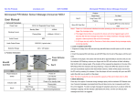
MSA1 Operating Procedure
Tension/Compression Testing Using the Fiber/Film Tool
TA Instruments RSAIII Micro-Strain Analyzer
See RSA3 User Manual (pdf file located on computer desktop)
Start-Up
1. Log in usage using the SMIF web site. You will need to use another computer in the
lab as the MSA computer is not networked
2. Turn up the air supply until the pressure reads 80psi
3. Turn on the power switch located on the back left side of the tool
4. Login to Windows on the MSA1 computer. Choose SMIF user and enter SMIF as the
password
5. Open the TA Orchestrator software on the computer
6. Turn the transducer motor on and set oven temperature (if desired)
a. From the Control pull-down menu, select Instrument Control Panel
b. Click the Motor Power On button
c. If you want to use the oven for the measurement:
i. Type in the desired temperature( 25C – 600C)
ii. Set temperature control to Oven
iii. Click the Environmental Controller On button
d. Click OK
Tool and Sample Mounting (see pages 93-96 in RSA3 User Manual)
7. From the Control pull-down menu, select Gap Control Panel and click on Send to
Top to raise the motor to the tool loading position.
8. Click on Offset Force to Zero
9. Mount the upper and lower Fiber/Film tools on the actuator shafts. The longer piece
is mounted on the top and the shorter piece is mounted on the bottom.
10. Verify that the Force in the Gap/Instrument Control panel reads -97.6gm ± 1.0gm
with the longer Fiber/Film tool mounted on top. If the force value is different than
this, contact SMIF to perform a tool mass calibration.
11. Click on Offset Force to Zero to zero the normal force on the motor with no sample
present
12. Using the stepper control buttons on the ride side of the instrument, lower the stage to
a point where the upper and lower tools are close but not touching.
13. Click on Zero Fixture button to determine the zero point for the Fiber/Film tools.
Note: The fixture should be zeroed at the temperature you will run the experiment.
14. Enter the desired Commanded Gap and Max allowed Force based on your sample
geometry. Commanded gap is the desired approximate sample length for the
measurement. Typical values for tensile testing are 10mm for the gap and 500g for
the force.
15. Click on Set Gap to move the stage to the approximate desired sample length.
16. Mount the sample
a. Loosen the screws and place the sample between the jaws of the upper and
lower Fiber/Film tools
MSA1 Operating Procedure for Tension/Compression Testing Using the Fiber/Film Tool
Page 1 of 3
Revision 1
10/13/2010
M. Walters
b. Use the hex torque wrench to tighten the screws and hold the sample in place.
A torque setting of 15-20 is a good starting point.
c. Adjust the screw tightness (if needed) to get the measured force back close to
zero. Too tight and additional torque forces will be placed on the sample.
Too loose and the sample might slip during the measurement.
d. Examine the sample to ensure that it does not have wrinkles or kinks.
17. Click on the Move Stage buttons to slightly increase the gap distance to provide a
very slight tension (less than -1gm is possible) as indicated by the Force meter
18. Click Exit in the Gap/Instrument Control Panel
Test Set-Up and Measurement (See Chapter 3 in the RSA3 User Manual)
19. Click the green START button to enter the Edit/Start Instrument Test panel.
20. Click on Save As to select your directory.
a. You should save your data in your own folder located in the “User Data”
folder on the desktop
b. Enter a filename (e.g., sample name) and click Save
21. Enter Operator and Test Notes if desired
22. Under Sample Geometry:
a. Select the Predefined Geometries button (Note: you can also save geometry
settings and recall them by selecting the Stored Geometries button)
b. In the Geometry pull down menu select:
i. Rectangular Tension/Compression Geometry for film samples or
ii. Cylindrical Tension/Compression Geometry for fiber samples
c. Click on Edit Geometry and enter the sample dimensions. Check “Read Test
Fixture Gap” to have the system automatically measure the sample length at
the start of the test.
d. Click on Options and verify that the tool mass = 97.6gm
e. Click OK twice to exit the Geometry menu windows
23. Under Test Set-Up:
a. Select the Predefined Test Setups button (Note: you can also save test setup
settings and recall them by selecting the Stored Test Setups button)
b. Select the desired Measurement Type button (Dynamic or Transient) and
select the desired Test Setup from the pull-down menu. See Chapter 3 in the
RSA3 User Manual for a description of the various Test Setups. A typical test
setup would be to select the Transient button and the Multiple Extension
Mode Test from the pull down menu.
c. Click Edit Test to edit the test parameters. Click on Help button for an
explanation of the test parameter settings. (Note: a positive extension value
will pull the tools apart for tension testing and a negative extension value will
push the tools together for compression testing)
24. Click Begin Test to start the test
25. The data will be plotted in real time
a. Graphing options can be modified by right clicking on the graph and selecting
Plot Set-Up.
i. Select the Layout tab to change the axes of the plot
MSA1 Operating Procedure for Tension/Compression Testing Using the Fiber/Film Tool
Page 2 of 3
Revision 1
10/13/2010
M. Walters
ii. Click on Help under each of the page tabs to read a description of the
various graphing options.
b. You can toggle between graph display and spreadsheet display by clicking on
the “Toggle Plot/Spreadsheet” icon
26. See Help files for descriptions of various data analysis functions
Saving Data
Please save all data in your directory in the User Data folder on the desktop
27. To save the data in the Orchestrator format
a. From the File pull down menu choose Save As and type in filename and
select your directory in the User Data folder.
28. To save the data in the Text format
a. From the File pull down menu choose Export
b. Select your directory in the User Data folder and type in a filename
c. Under the Save as Type pull down menu, select Excel Ascii
29. To save a picture of a graph:
a. From the Choose Copy from the Edit pull down menu (or press Ctrl+C).
Open up the Paint application and choose Paste. You can then save the graph
in a number of different picture formats (e.g., tiff, jpeg, etc).
Shut Down
30. From the Control pull-down menu, select Gap Control Panel and click on Set Gap
to move the motor to the original sample load position
31. Unload your sample
32. Click on Send to Top to raise the motor to the tool loading position
33. Remove the upper and lower Fiber/Film tools and place the tools and hex torque
wrench in the black storage box
34. Click Exit in the Gap/Instrument Control Panel
35. Turn off the transducer motor and oven (if used)
a. Select Instrument Control Panel from the Control pull-down menu
b. Click Motor Power Off button and Environmental Controller Off button
c. Click OK
36. Exit the TA Orchestrator software
37. Turn off the power switch located on the back left side of the tool
38. Turn off the air supply
39. Log out usage using the SMIF web site. You will need to use another computer in the
lab as the MSA computer is not networked.
MSA1 Operating Procedure for Tension/Compression Testing Using the Fiber/Film Tool
Page 3 of 3
Revision 1
10/13/2010
M. Walters