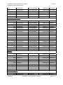
1
WORK ORDER NO. 1181373 Supervisory Control and Data Acquisition System (SCADA) Upgrade At the Naval Station, Norfolk, Virginia PREPARED BY: NAVFAC MID-ATLANTIC Norfolk, VA 23511 Electrical: Mythy T. Tran Submitted By: C. Jeffrey Morton Date: July 25, 2012 APPROVED BY: Director of Design: For Commander, NAVFAC Mid-Atlantic: Date: July 25, 2012 Alan D. Johnson, R.A. Naval Station Norfolk SCADA System Upgrade Naval Station Norfolk, Norfolk, Virginia 1181373 Naval Station Norfolk SCADA System Upgrade Naval Station Norfolk, Norfolk, Virginia PART ONE – PROPOSAL FORMS & DOCUMENTS 1181373 Naval Station Norfolk SCADA System Upgrade Naval Station Norfolk, Norfolk, Virginia 1181373 Naval Station Norfolk SCADA System Upgrade Naval Station Norfolk, Norfolk, Virginia 1181373 1.0 Table of Contents (RFP Parts 2-6) 1. PART 2 – GENERAL REQUIREMENTS 01 14 00.05 20 01 20 00.05 20 01 30 00.05 20 01 31 19.05 20 01 32 16.00 20 01 32 17.05 20 01 33 00.05 20 01 33 10.05 20 01 35 13.05 20 01 35 29.05 20 WORK RESTRICTIONS FOR DESIGN-BUILD PRICE AND PAYMENT PROCEDURES FOR DESIGN-BUILD ADMINISTRATIVE REQUIREMENTS FOR DESIGN-BUILD POST AWARD MEETINGS DESIGN AND CONSTRUCTION PROGRESS DOCUMENTATION NETWORK ANALYSIS SCHEDULES (NAS) FOR DESIGN-BUILD CONSTRUCTION SUBMITTAL PROCEDURES DESIGN SUBMITTAL PROCEDURES SPECIAL PROJECT PROCEDURES FOR DESIGN-BUILD SAFETY AND OCCUPATIONAL HEALTH REQUIREMENTS FOR DESIGN-BUILD 01 45 00.05 20 DESIGN AND CONSTRUCTION QUALITY CONTROL 01 50 00.05 20 TEMPORARY FACILITIES AND CONTROLS FOR DESIGN-BUILD 01 57 19.00 20 TEMPORARY ENVIRONMENTAL CONTROLS 01 57 19.01 20 SUPPLEMENTAL TEMPORARY ENVIRONMENTAL CONTROLS 01 74 19.05 20 CONSTRUCTION AND DEMOLITION WASTE MANAGEMENT FOR DESIGN-BUILD 01 78 23 OPERATION AND MAINTENANCE DATA 01 78 24.05 20 FACILITY OPERATION AND MAINTENANCE SUPPORT INFORMATION 2. PART 3 – PROJECT PROGRAM CHAPTER 1 & 2. PROJECT DESCRIPTION AND PROJECT OBJECTIVES CHAPTER 3. SITE ANALYSIS CHAPTER 6. ENGINEERING SYSTEMS REQUIREMENTS 3. PART 4 – PERFORMANCE TECHNICAL SPECIFICATIONS D50 ELECTRICAL G40 SITE ELECTRICAL UTILITIES Z10 GENERAL PERFORMANCE TECHNICAL SPECIFICATION 4. PART 5 – PRESCRIPTIVE SPECIFICATIONS 25 10 00.00 20 SUPERVISORY CONTROL AND DATA ACQUISITION (SCADA) SYSTEM 26 20 00 INTERIOR DISTRIBUTION SYSTEM 5. PART 6 – ATTACHMENTS ELECTRICAL SUBSTATION SCADA EQUIPMENT INVENTORY LISTING T-1 SITE PLAN E-1 ELECTRICAL SUBSTATION LOCATIONS E-2 SCADA SYSTEM CONNECTIVITY DIAGRAM E-3 34500 VAC ELECTRICAL DISTRIBUTION SYSTEM 1-LINE DIAGRAM E-4 11500 VAC ELECTRICAL DISTRIBUTION SYSTEM 1-LINE DIAGRAM E-5 PIER ELECTRICAL DISTRIBUTION SYSTEM 1-LINE DIAGRAM U_IDPS_SRG_V1R03_OVERVIEW SECURITY REQUIREMENTS GUIDE (SRG) Naval Station Norfolk SCADA System Upgrade Naval Station Norfolk, Norfolk, Virginia 1181373 Naval Station Norfolk SCADA System Upgrade Naval Station Norfolk, Norfolk, Virginia 1181373 PART 2 – GENERAL REQUIREMENTS 01 14 00.05 20 01 20 00.05 20 01 30 00.05 20 01 31 19.05 20 01 32 16.00 20 01 32 17.05 20 01 33 00.05 20 01 33 10.05 20 01 35 13.05 20 01 35 29.05 20 WORK RESTRICTIONS FOR DESIGN-BUILD PRICE AND PAYMENT PROCEDURES FOR DESIGN-BUILD ADMINISTRATIVE REQUIREMENTS FOR DESIGN-BUILD POST AWARD MEETINGS DESIGN AND CONSTRUCTION PROGRESS DOCUMENTATION NETWORK ANALYSIS SCHEDULES (NAS) FOR DESIGN-BUILD CONSTRUCTION SUBMITTAL PROCEDURES DESIGN SUBMITTAL PROCEDURES SPECIAL PROJECT PROCEDURES FOR DESIGN-BUILD SAFETY AND OCCUPATIONAL HEALTH REQUIREMENTS FOR DESIGN-BUILD 01 45 00.05 20 DESIGN AND CONSTRUCTION QUALITY CONTROL 01 50 00.05 20 TEMPORARY FACILITIES AND CONTROLS FOR DESIGN-BUILD 01 57 19.00 20 TEMPORARY ENVIRONMENTAL CONTROLS 01 57 19.01 20 SUPPLEMENTAL TEMPORARY ENVIRONMENTAL CONTROLS 01 74 19.05 20 CONSTRUCTION AND DEMOLITION WASTE MANAGEMENT FOR DESIGN-BUILD 01 78 23 OPERATION AND MAINTENANCE DATA 01 78 24.05 20 FACILITY OPERATION AND MAINTENANCE SUPPORT INFORMATION Naval Station Norfolk SCADA System Upgrade Naval Station Norfolk, Norfolk, Virginia 1181373 Naval Station Norfolk SCADA System Upgrade Naval Station Norfolk, Norfolk, Virginia 1181373 SECTION 01 14 00.05 20 WORK RESTRICTIONS FOR DESIGN-BUILD 03/12 PART 1 GENERAL 1.1 SUBMITTALS The use of a "G" following a submittal indicates that a Government approval action is required. Submit the following in accordance with Section 01 33 10.05 20 DESIGN SUBMITTAL PROCEDURES and Section 01 33 00.05 20 CONSTRUCTION SUBMITTAL PROCEDURES. SD-01 Preconstruction Submittals List of contact personnel; G 1.2 SPECIAL SCHEDULING REQUIREMENTS a . Have materials, equipment, and personnel required to perform the work at the site prior to the commencement of the work. Specific items of work to which this requirement applies include: (1) Electrical substation equipment installation (2) SCADA System c. The SCADA system and electrical substations will remain in operation during the entire construction period. Conduct operations so as to cause the least possible interference with normal operations of the activity. d. Permission to interrupt any Activity roads, railroads, and/or utility service shall be requested in writing a minimum of 15 calendar days prior to the desired date of interruption. e. The work under this contract requires special attention to the scheduling and conduct of the work in connection with existing operations. Identify on the construction schedule each factor which constitutes a potential interruption to operations. The following conditions apply: (1) Current Operational SCADA functions must be completely demonstrated on the new SCADA system prior to deactivation of the current SCADA system. 1.3 1.3.1 CONTRACTOR ACCESS AND USE OF PREMISES Activity Regulations Ensure that Contractor personnel employed on the Activity become familiar with and obey Activity regulations including safety, fire, traffic and Section 01 14 00.05 20 Page 1 Naval Station Norfolk SCADA System Upgrade Naval Station Norfolk, Norfolk, Virginia 1181373 security regulations. Keep within the limits of the work and avenues of ingress and egress. To minimize traffic congestion, delivery of materials shall be outside of peak traffic hours (6:30 to 8:00 a.m. and 3:30 to 5:00 p.m.) unless otherwise approved by the Contracting Officer. Wear hard hats in designated areas. Do not enter any restricted areas unless required to do so and until cleared for such entry. The Contractor's equipment shall be conspicuously marked for identification. 1.3.1.1 Subcontractors and Personnel Contacts Furnish a list of contact personnel of the Contractor and subcontractors including addresses and telephone numbers for use in the event of an emergency. As changes occur and additional information becomes available, correct and change the information contained in previous lists. 1.3.1.2 Identification Badges Identification badges, if required, will be furnished without charge. Application for and use of badges will be as directed. Furnish a completed EMPLOYMENT ELIGIBILITY VERIFICATION form (DHS FORM I-9) for all personnel requesting badges. This form is available at http://www.uscis.gov/files/form/i-9.pdf . Immediately report instances of lost or stolen badges to the Contracting Officer. 1.3.2 Working Hours Regular working hours shall consist of an 8 1/2 hour period, between 7 a.m. and 3:30 p.m., Monday through Friday, excluding Government holidays. 1.3.3 Work Outside Regular Hours Work outside regular working hours requires Contracting Officer approval. Make application 15 calendar days prior to such work to allow arrangements to be made by the Government, giving the specific dates, hours, location, type of work to be performed, contract number and project title. Based on the justification provided, the Contracting Officer may approve work outside regular hours. During periods of darkness, the different parts of the work shall be lighted in a manner approved by the Contracting Officer. 1.3.4 Occupied and Existing Buildings The Contractor shall be working in an existing building and around existing buildings which are occupied. Do not enter the buildings without prior approval of the Contracting Officer. The existing buildings and their contents shall be kept secure at all times. Provide temporary closures as required to maintain security as directed by the Contracting Officer. Provide dust covers or protective enclosures to protect existing work that remains and Government material during the construction period. Relocate movable furniture as required to perform the work, protect the furniture, and replace the furniture in their original locations upon completion of the work. Leave attached equipment in place, and protect them Section 01 14 00.05 20 Page 2 Naval Station Norfolk SCADA System Upgrade Naval Station Norfolk, Norfolk, Virginia 1181373 against damage, or temporarily disconnect, relocate, protect, and reinstall them at the completion of the work. 1.3.5 Utility Cutovers and Interruptions a. Make utility cutovers and interruptions after normal working hours or on Saturdays, Sundays, and Government holidays. Conform to procedures required in the paragraph "Work Outside Regular Hours." b. Ensure that new utility lines are complete, except for the connection, before interrupting existing service. c. Interruption to water, sanitary sewer, storm sewer, telephone service, electric service, air conditioning, heating, fire alarm, and compressed air shall be considered utility cutovers pursuant to the paragraph entitled "Work Outside Regular Hours." d. Operation of Station Utilities: The Contractor shall not operate nor disturb the setting of control devices in the station utilities system, including water, sewer, electrical, and steam services. 1.3.5.1 Location of Underground Utilities Obtain digging permits prior to start of excavation by contacting the Contracting Officer 15 calendar days in advance. Scan the construction site with electromagnetic or sonic equipment, and mark the surface of the ground or paved surface where existing underground utilities or utilities encased in pier structures are discovered. Verify the elevations of existing piping, utilities, and any type of underground or encased obstruction not indicated to be specified or removed but indicated or discovered during scanning in locations to be traversed by piping, ducts, and other work to be conducted or installed. a. Notification Prior to Excavation: Notify the Contracting Officer at least 15 days prior to starting excavation work. Contact Miss Utility 48 hours prior to excavating. Contractor is responsible for marking all utilities not marked by Miss Utility. 1.4 SECURITY REQUIREMENTS Contract Clause "FAR 52.204-2, Security Requirements and Alternate II," "FAC 5252.236-9301, Special Working Conditions and Entry to Work Area". 1.4.1 Naval Base, Norfolk, VA a. Contractor registration. Register with the Base Police Truck Investigation Team, located behind Pass and ID Office (Building CD-9) on Hampton Blvd, Naval Air Station, Norfolk, VA 23511-5000, telephone number (757) 322-2979. b. Storage and office trailer registration. Register storage and office trailers to be used on base with the truck investigation team. Trailers shall meet State law requirements and shall be in good condition. (1) Trailers shall be lockable and shall be locked when not in use. Section 01 14 00.05 20 Page 3 Naval Station Norfolk SCADA System Upgrade Naval Station Norfolk, Norfolk, Virginia 1181373 (2) Trailers shall have a sign in the lower left hand corner of left door of trailer with the following information: Company name, address, registration number of trailer or vehicle identification number, location on base, duration of contract or stay on base, contract number, local on-base phone number, off-base phone number of main office, and emergency recall person and phone number. c. Equipment markings. Equipment owned or rented by the company shall have the company name painted or stenciled on the equipment in a conspicuous location. Rented equipment is to be conspicuously marked with a tag showing who rented the equipment. Register the equipment with the truck investigation team. d. Procedure information. For additional information regarding registration procedures, contact the Officer in Charge of Construction at (757) 445-1463 or Base Police at (757) 322-4500. PART 2 PRODUCTS Not used. PART 3 EXECUTION Not used. -- End of Section --- End of Section -- Section 01 14 00.05 20 Page 4 Naval Station Norfolk SCADA System Upgrade Naval Station Norfolk, Norfolk, Virginia 1181373 SECTION 01 20 00.05 20 PRICE AND PAYMENT PROCEDURES FOR DESIGN-BUILD 03/12 PART 1 1.1 GENERAL REFERENCES The publications listed below form a part of this specification to the extent referenced. The publications are referred to within the text by the basic designation only. U.S. ARMY CORPS OF ENGINEERS (USACE) EP-1110-1-8 1.2 (2003) Construction Equipment Ownership and Operating Expense Schedule, Vol 1-12 SUBMITTALS The use of a "G" following a submittal indicates that a Government approval action is required. Submit the following in accordance with Section 01 33 10.05 20 DESIGN SUBMITTAL PROCEDURES and Section 01 33 00.05 20 CONSTRUCTION SUBMITTAL PROCEDURES. SD-01 Preconstruction Submittals Schedule of prices; G 1.3 SCHEDULE OF PRICES 1.3.1 Schedule Instructions Payments will not be made until the Preliminary Schedule of Prices or Cost Loaded Critical Path Method (CPM) schedule has been submitted to and accepted by the Contracting Officer. The Schedule of Prices shall be separated as follows: a. Primary Facility/s Cost Breakdown: Defined as work on the primary facility/s out to the 1.5 m (5 foot) line. Work out to the 1.5 m (5 foot) line shall include construction encompassed within a theoretical line 1.5 m (5 foot) from the face of exterior walls and shall include attendant construction, such as pad mounted HVAC equipment, that may extend beyond the 1.5 m (5 foot) line. b. Supporting Facilities Cost Breakdown: Defined as site work, including incidental work, outside the 1.5 m (5 foot) line. 1.3.1.1 Additional Facility Price Data For the purposes of historical pricing data collection for Government use only, simultaneously submit this data to the NAVFAC Chief Cost Engineer at the following mailing or email address within 30 days of contract award: Section 01 20 00.05 20 Page 1 Naval Station Norfolk SCADA System Upgrade Naval Station Norfolk, Norfolk, Virginia 1181373 a. Commander Naval Facilities Engineering Command Atlantic 6505 Hampton Blvd. Norfolk, VA 23508-1278 Attention: CI Cost b. [email protected] This information is for Government internal purposes only for tracking historical primary and support facility pricing and will not be used for any scope, price, or evaluation purposes. 1.3.2 Data Required If the contract requires the use of a cost loaded CPM the information required for the Schedule of Prices will be entered as an integral part of the Network Analysis Schedule (NAS) and its Mathematical Analysis. Provide a detailed breakdown of the contract price, giving quantities for each of the various kinds of work, unit prices, and extended prices therefore. Costs shall be summarized and totals provided for each construction category. 1.3.3 Construction Categories The following construction categories apply to work covered by this specification. These construction categories are found in the DD Form 1391. CATEGORY DESCRIPTION _____ _____ Contractor shall determine all additional applicable Construction Categories from the "Category Codes for Military Real Property", which is available from the Contracting Officer. Divide detailed breakdown into each construction category, sufficient for completion of the DD Form 1354, Transfer and Acceptance of Military Real Property. Subcontractors who may be involved in work under more than one of these categories shall be advised of this requirement in order to furnish such data without delay. Construction categories given above may be modified by the Contracting Officer as necessary during course of work. Cost data accumulated under this section are required in the preparation of DD Form 1354. Coordinate with UFGS Section 01 33 10.05 20, Design Submittal Procedures paragraph "DD Form 1354". 1.4 CONTRACT MODIFICATIONS In conjunction with the Contract Clause "DFARS 252.236-7000, Modification Proposals-Price Breakdown," and where actual ownership and operating costs of construction equipment cannot be determined from Contractor accounting records, equipment use rates shall be based upon the applicable provisions of the EP-1110-1-8. 1.5 1.5.1 CONTRACTOR'S INVOICE AND CONTRACT PERFORMANCE STATEMENT Content of Invoice Section 01 20 00.05 20 Page 2 Naval Station Norfolk SCADA System Upgrade Naval Station Norfolk, Norfolk, Virginia 1181373 Requests for payment will be processed in accordance with the Contract Clause "FAR 52.232-27, Prompt Payment Construction Contracts," and shall include items required by FAR 52.232-5, "Payments under Fixed-Price Construction Contracts" and the following: a. The Contractor's invoice certified by QC, on the form furnished by the Government for this purpose, showing in summary form, the basis for arriving at the amount of the invoice. Submit number of copies required by the Contracting Officer. b. The Contract Performance Statement on the form furnished by the Government for this purpose, showing in detail, the estimated cost, percentage of completion, and value of completed performance. Submit number of copies required by the Contracting Officer. c. Final invoice shall be accompanied by Final Release Form. If the contractor is incorporated, the release shall contain the corporate seal. An officer of the corporation shall sign the release and the corporate secretary shall certify the release. d. Updated schedule if not already submitted per Section 01 32 17.05 20. e. Contractor Safety Self Evaluation Checklist (original). f. Monthly Work-hour Report. g. Solid Waste Disposal Report. 1.5.2 Mailing of Invoices a. All invoices shall be forwarded with specific marking on the envelope. This marking shall be in the front lower left hand corner, in large letters, "INVOICES - ENCLOSED." b. Invoices not completed in accordance with contract requirements will be returned to the Contractor for correction of the deficiencies. c. Final invoices not accompanied by Final Release Form will be considered incomplete and will be returned to the Contractor. 1.6 PAYMENTS TO THE CONTRACTOR Payments will be made on submission of itemized requests by the Contractor which comply with the requirements of this section, and will be subject to reduction for overpayments or increase for underpayments made on previous payments to the Contractor. a. Basis for Contracting Officer's consideration to allow progress payment for material delivered on the site (but not installed) and for completed preparatory work, as authorized under FAR 52.232-5(b), shall be (1) major high cost items and (2) long lead special order items. Materials that will not be paid for prior to installation include, but are not limited to, bulk quantities such as nails, fasteners, conduits, gypsum board, etc. In the request for progress payment, such items shall be specifically identified in the Contractor's estimates of work Section 01 20 00.05 20 Page 3 Naval Station Norfolk SCADA System Upgrade Naval Station Norfolk, Norfolk, Virginia 1181373 submitted for the Contracting Officer's approval in accordance with paragraph entitled "Schedule of Prices" above. At the time of invoicing, the amount billed shall be supported by documents establishing its value. PART 2 PRODUCTS Not used. PART 3 EXECUTION Not used. -- End of Section --- End of Section -- Section 01 20 00.05 20 Page 4 Naval Station Norfolk SCADA System Upgrade Naval Station Norfol, Norfolk, Virginia 1181373 SECTION 01 30 00.05 20 ADMINISTRATIVE REQUIREMENTS FOR DESIGN-BUILD 03/12 PART 1 1.1 GENERAL SUBMITTALS The use of a "G" following a submittal indicates that a Government approval action is required. Submit the following in accordance with Section 01 33 10.05 20 DESIGN SUBMITTAL PROCEDURES and Section 01 33 00.05 20 CONSTRUCTION SUBMITTAL PROCEDURES. SD-01 Preconstruction Submittals Insurance; G 1.2 MINIMUM INSURANCE REQUIREMENTS Procure and maintain during the entire period of performance under this contract the following minimum insurance coverage: a. Comprehensive general liability: $500,000 per occurrence b. Automobile liability: $200,000 per person, $500,000 per occurrence for bodily injury, $20,000 per occurrence for property damage c. Workmen's compensation as required by Federal and State workers' compensation and occupational disease laws. d. Employer's liability coverage of $100,000, except in States where workers compensation may not be written by private carriers, e. Others as required by the State. 1.3 CONTRACTOR PERSONNEL REQUIREMENTS 1.3.1 1.3.1.1 Subcontractor Special Requirements Asbestos Containing Material All contract requirements of PART 4, F20 SELECTIVE BUILDING DEMOLITION, assigned to the Private Qualified Person (PQP) shall be accomplished directly by a first tier subcontractor. 1.3.1.2 HVAC TAB All contract requirements of TAB work required by PART 4 D30, HVAC, shall be accomplished directly by a first tier subcontractor. No TAB work required by PART 4, D30, HVAC, shall be accomplished by a second tier subcontractor. 1.3.1.3 Qualified Testing Organization All contract requirements of work required to be performed by a Qualified Testing Organization in PART 4, D50 ELECTRICAL and G40 SITE ELECTRICAL Section 01 30 00.05 20 Page 1 Naval Station Norfolk SCADA System Upgrade Naval Station Norfol, Norfolk, Virginia 1181373 UTILITIES, shall be accomplished directly by a first tier subcontractor. No work to be performed by a Qualified Testing Organization, required by PART 4, D50 and G40 shall be accomplished by a second tier subcontractor. 1.4 SUPERVISION Have at least one qualified supervisor capable of reading, writing, and conversing fluently in the English language on the job site during working hours. In addition, the Quality Control (QC) representative shall also have fluent English communication skills. 1.5 AVAILABILITY OF CADD DRAWING FILES After award and upon request, the electronic "Computer-Aided Drafting and Design (CADD)" drawing files will be made available to the Contractor for use in preparation of construction drawings and data related to the referenced contract subject to the following terms and conditions. Data contained on these electronic files shall not be used for any purpose other than as a convenience in the preparation of construction drawings and data for the referenced project. Any other use or reuse shall be at the sole risk of the Contractor and without liability or legal exposure to the Government. The Contractor shall make no claim and waives to the fullest extent permitted by law, any claim or cause of action of any nature against the Government, its agents or sub consultants that may arise out of or in connection with the use of these electronic files. The Contractor shall, to the fullest extent permitted by law, indemnify and hold the Government harmless against all damages, liabilities or costs, including reasonable attorney's fees and defense costs, arising out of or resulting from the use of these electronic files. These electronic CADD drawing files are not construction documents. Differences may exist between the CADD files and the corresponding construction documents. The Government makes no representation regarding the accuracy or completeness of the electronic CADD files, nor does it make representation to the compatibility of these files with the Contractors hardware or software. In the event that a conflict arises between the signed and sealed construction documents prepared by the Government and the furnished CADD files, the signed and sealed construction documents shall govern. The Contractor is responsible for determining if any conflict exists. Use of these CADD files does not relieve the Contractor of duty to fully comply with the contract documents, including and without limitation, the need to check, confirm and coordinate the work of all contractors for the project. If the Contractor uses, duplicates and/or modifies these electronic CADD files for use in producing construction drawings and data related to this contract, all previous indicia of ownership (seals, logos, signatures, initials and dates) shall be removed. 1.6 CLEANUP Leave premises "broom clean." Clean interior and exterior glass surfaces exposed to view; remove temporary labels, stains and foreign substances; polish transparent and glossy surfaces; vacuum carpeted and soft surfaces. Clean equipment and fixtures to a sanitary condition. Clean filters of operating equipment. Clean debris from roofs, gutters, downspouts and Section 01 30 00.05 20 Page 2 Naval Station Norfolk SCADA System Upgrade Naval Station Norfol, Norfolk, Virginia 1181373 drainage systems. Sweep paved areas and rake clean landscaped areas. Remove waste and surplus materials, rubbish and construction facilities from the site. PART 2 PRODUCTS Not used. PART 3 EXECUTION Not used. -- End of Section --- End of Section -- Section 01 30 00.05 20 Page 3 Naval Station Norfolk SCADA System Upgrade Naval Station Norfolk, Norfolk, Virginia 1181373 SECTION 01 31 19.05 20 POST AWARD MEETINGS 03/12 PART 1 1.1 GENERAL SUMMARY This document includes post-award requirements for project kickoff and subsequent design and preconstruction meetings. 1.2 SUBMITTALS The use of a "G" following a submittal indicates that a Government approval action is required. Submit the following in accordance with Section 01 33 10.05 20 DESIGN SUBMITTAL PROCEDURES. SD-01 Preconstruction Submittals Design Submittal Packaging Proposal; G Project Schedule; G Performance Assessment Plan (PAP); G Design Presentation Concept Site and Floor Plans; G 1.3 POST AWARD KICKOFF MEETING The Post Award Kickoff (PAK) meeting is made up of Contract Administration, Concept Design Presentation/Design Development or Concept Design Workshop (CDW), Partnering, and Scheduling. If mutually beneficial to the Contractor and the Government, these four elements may be addressed in a single meeting or multiple meetings. 1.3.1 PAK Meeting Schedule and Location Within 21 calendar days after contract award, and prior to commencing work, meet with the Contracting Officer for the PAK meeting(s). The meeting shall be located at a specific time and place to be determined by the Contracting Officer. 1.3.2 PAK Meeting Outcomes The meeting(s) outcomes are: a. Integrate the Contractor and all client representatives into the project team. b. Achieve consensus from the project team on any issues and concerns with the Contractor's technical proposal and the User's functional requirements. Confirm the design is within the project budget. Section 01 31 19.05 20 Page 1 Naval Station Norfolk SCADA System Upgrade Naval Station Norfolk, Norfolk, Virginia 1181373 c. Establish and explain policies and procedures for completion of a successful project. d. Establish clear lines of communication and points of contact for Government and Contractor team members. e. Obtain an acceptable conceptual design including floor and site plans, signed by the client, Contractor and other key team members. f. Establish project design schedule, design submittal packaging, and preliminary construction schedule in accordance with UFGS Section 01 32 17.05 20, Network Analysis Schedule (NAS) for Design-Build. Discuss design milestones and events that will should be included in the Quality Control Communication Plan. g. Establish clear expectations for facility turnover. h. Establish procedure for design packages reviews, Contractor's resolution to comments, and Government's role in review of packages. 1.3.3 PAK Meeting Contractor Attendees The following Contractor key personnel shall attend the PAK: Project Manager, Project Scheduler, Lead Designer-of-Record (DOR), Design Staff responsible for each architectural/engineering discipline when facility design is discussed, Superintendent, and QC Manager. Optional attendees include: Principal, Assistant Project Manager, major subcontractors and specialized supplemental QC personnel. 1.3.4 Contract Administration Contract administration roles and responsibilities will be addressed. 1.3.5 Design Presentation/Development The Contractor shall lead discussions to develop an understanding of the accepted technical proposal and conduct working sessions to further develop the approved conceptual site, floor plans, and building elevation. The Contractor shall anticipate that Users represented at the Design Presentation will provide additional functional information. At the end of the Design Presentation the Contractor shall provide either assurance that the updated design can be built with-in the budget or identify potential cost modification items and establish a follow-on Design Presentation Meeting to finalize a design that will include trade-offs to bring the project within the budget. 1.3.5.1 Design Presentation/Development Contractor Meetings Attendees The following Contractor key personnel shall attend the Design Presentation: Project Manager, Project Scheduler, Cost Estimator, Lead Designer of Record, Design Staff responsible for each architectural/engineering discipline when facility design is discussed, Major Subcontractors, and DQC. 1.3.6 Partnering Section 01 31 19.05 20 Page 2 Naval Station Norfolk SCADA System Upgrade Naval Station Norfolk, Norfolk, Virginia 1181373 LEVEL A PARTNERING: The Contractor shall conduct partnering sessions with key personnel of the project team, including Contractor's personnel and government personnel. The partnership will draw on the strength of each organization in an effort to achieve a quality project done right the first time, within budget, on schedule, and without any safety mishaps. To most effectively accomplish this contract, the Government requires the formation of a cohesive partnership with the Contractor and its subcontractors. Key personnel, including the client who will occupy the facility, principal individuals from NAVFAC (Echelon III and/or IV), PWD FEAD, PM&E Branch, Construction Manager (CM)/ Resident Officer in Charge of Construction (ROICC), the project sponsor, and representative(s) of the facility owner will be invited to participate in the partnering process. Key members of the prime and subcontractors teams, including senior management, must participate. The Contractor shall pay all costs associated with the partnering effort including facilitator, meeting room and other incidental items. Before the partnering session, the contractor shall coordinate with the facilitator requirements for incidental items (audio-visual equipment, two easels, flipchart paper, colored markers, note paper, pens/pencils, colored flash cards, etc.) and have these items available at the partnering session. The contractor will copy documents for distribution to all attendees. The participants shall bear their own costs for meals, lodging and transportation associated with partnering. a. The Initial Partnering Session shall be a duration of one day minimum Located at a place off base as agreed to by the partners. May take place concurrently with the PAK Meeting with Contractor's Participants to include those listed in paragraph "PAK Meeting Attendees". The Contractor shall provide a Facilitator who is experienced in conducting Partnering Workshops. The Facilitator is responsible for leading the team in a timely manner and making sure that issues are identified and resolved. The Facilitator shall be acceptable to the CM/ROICC. b. The Follow on Partnering Session(s) generally lasts a half day or less and is encouraged to utilize electronic means to expedite meetings. Meetings may be held at a location off Base, at the project site, or in a Government Facility on Base. Schedule quarterly meetings and may be held concurrently with other scheduled meetings, such as QC meetings. Participants may be only those required to resolve current issues. No facilitator required unless desired by the partners. 1.3.6.1 Performance Assessment Plan (PAP) The Performance Assessment Plan (PAP) shall be used to document design innovation and budget management, provide performance feedback to the Contractor, and as a basis for interim and final evaluations in the Construction Contractor Appraisal System (CCASS) on-line database. It is the intent of the Government to establish the PAP based on tangible, measurable indicators of outstanding contractor performance, and on commitments made in the Contractor's proposal. The initial PAP may be found on the NAVFAC Design-Build Request for Proposal Website in RFP PART 6 Attachments. Review and finalized the initial PAP during the Partnering Section 01 31 19.05 20 Page 3 Naval Station Norfolk SCADA System Upgrade Naval Station Norfolk, Norfolk, Virginia 1181373 Session. During the initial Partnering Session, the Government, the Contractor, the Designer-of-Record, and the Client will establish the PAP. Following the establishment of the PAP, the Contractor will present it, with his input, for update and discussion at projects meetings which discuss project performance. Submit an updated PAP on a monthly basis with the invoice for that period as a minimum. 1.3.7 Project Schedule Provide in accordance with Section 01 32 17.05 20 NETWORK ANALYSIS SCHEDULES (NAS) FOR DESIGN-BUILD. 1.4 DESIGN QUALITY ASSURANCE MEETINGS After Government Quality Assurance (QA) of each Design Submittal has been completed, meet with the Government for a one-day conference to discuss review comments for the specific design submittal. Provide consolidated copies of all Government comments with annotations of Contractor's action beside them. Notify the Contracting Officer in writing within five (5) days after receipt of Government's comments if the Contractor disagrees with comments technically or interprets comments to exceed the requirements of the contract. 1.4.1 Design QA Meeting Attendees The following Contractor key personnel shall attend the design QA meetings: Project Manager, QC Manager , and Contractor's Design Staff (architect and engineering disciplines related to topics to be discussed). 1.4.2 Design QA Meeting Location Meetings shall be located at the office of the Contracting Officer's QA Team or may be conducted at other locations or by other electronic means if mutually acceptable to all parties. 1.4.3 Minimum Design QA Meeting Agenda Address all Government comments that are unresolved and present clarification or supporting information requested by the Contracting Officer's QA team during the previous meeting. 1.5 PRECONSTRUCTION MEETING Meet with the Contracting Officer to discuss construction items of concern to the Government and the Contractor such as outages, storage, trailer location, disposal of construction debris, and safety, at a location to be determined by the Contracting Officer. The Preconstruction meeting may take place with the PAK meeting or at any time prior to mobilization and before any construction work begins. 1.6 1.6.1 RECURRING MEETINGS Quality Control and Production Meetings Quality Control and Production Meetings in accordance with UFGS Section 01 45 00.05 20, Design and Construction Quality Control. Section 01 31 19.05 20 Page 4 Naval Station Norfolk SCADA System Upgrade Naval Station Norfolk, Norfolk, Virginia 1.6.2 1181373 Safety Meetings Safety Meetings in accordance with UFGS Section 01 35 29.05 20, Safety and Occupational Health Requirements for Design-Build. PART 2 PRODUCTS Not Used. PART 3 EXECUTION Not Used. Section 01 31 19.05 20 Page 5 Naval Station Norfolk SCADA System Upgrade Naval Station Norfolk, Norfolk, Virginia 1181373 -- End of Section -- Section 01 31 19.05 20 Page 6 Naval Station Norfolk SCADA System Upgrade Naval Station Norfolk, Norfolk, Virginia 1181373 SECTION 01 32 16.00 20 DESIGN AND CONSTRUCTION PROGRESS DOCUMENTATION 03/11 PART 1 1.1 GENERAL SUBMITTALS Government approval is required for submittals with a "G" designation; submittals not having a "G" designation are for Contractor Quality Control approval. The following shall be submitted in accordance with Section 01 33 0005 20 CONSTRUCTION SUBMITTAL PROCEDURES: SD-01 Preconstruction Submittals Design and Construction schedule; G 1.2 DESIGN AND CONSTRUCTION SCHEDULE Prior to the start of work, prepare and submit to the Contracting Officer for acceptance a design and construction schedule in the form of a progress chart in accordance with the terms in Contract Clause "FAR 52.236-15, Schedules for Construction Contracts," except as modified in this contract. 1.3 NETWORK ANALYSIS SCHEDULE (NAS) The Contractor shall use the critical path method (CPM) to schedule and control construction activities. The Network shall have a minimum of 1 construction activities. The scheduling software that will be utilized by the Government on this project is SureTrak by Primavera Systems, Inc.. Notwithstanding any other provision in the contract, schedules submitted for this project must be prepared using either Primavera P3 or Primavera SureTrak (files saved in Concentric P3 format). Submission of data from another software system where data conversion techniques or software is used to import into Primavera's scheduling software is not acceptable and will be cause for rejection of the submitted schedule. The schedule shall identify as a minimum: 1.3.1 a. Design and Construction time for all major systems and components; b. Each activity shall be assigned its appropriate Responsibility Code; c. Each activity shall be assigned its appropriate Phase Code; d. Major submittals and submittal processing time; and e. Major equipment lead time. CPM Submittals and Procedures Submit all network analysis and updates in hard copy and on electronic media that is acceptable to the Contracting Officer. The project schedule will Section 01 32 16.00 20 Page 1 Naval Station Norfolk SCADA System Upgrade Naval Station Norfolk, Norfolk, Virginia 1181373 also be posted in the format specified as an Adobe PDF file with no relationship lines displayed in the graphic. The network analysis system shall be kept current, with changes made to reflect the actual progress and status of the construction. 1.4 UPDATED SCHEDULES Update the construction schedule and equipment delivery schedule at monthly intervals or when the schedule has been revised. Reflect any changes occurring since the last update. Submit copies of the purchase orders and confirmation of the delivery dates as directed. PART 2 PRODUCTS Not Used PART 3 EXECUTION Not Used -- End of Section -- Section 01 32 16.00 20 Page 2 Naval Station Norfolk SCADA System Upgrade Naval Station Norfolk, Norfolk, Virginia 1181373 SECTION 01 32 17.05 20 NETWORK ANALYSIS SCHEDULES (NAS) FOR DESIGN-BUILD 03/11 PART 1 1.1 GENERAL DESCRIPTION The Contractor is responsible for scheduling all design, procurement and construction. A single schedule shall logically incorporate all design and construction for the entire project. Unless otherwise indicated, the contractor may begin construction when design is signed, stamped and submitted to the Government via the Contractor's quality control organization. If Government approval is required for any portion of a final signed and sealed design package prior to construction, that review time shall be included in the schedule. The schedule shall also include times for procurement, Contractor quality control and construction, acceptance testing and training. Refer to Specification Section 01 33 00.05 20 Construction Submittal Procedures to determine if any items require Government approval prior to construction; if any are required, that submittal review time shall be included in the schedule. The schedule is a tool to manage the project, both for Contractor and Government activities. It will also be used to measure progress and to evaluate time extensions. If cost-loaded, it will provide the basis for progress payments. The Contractor shall use the Critical Path Method (CPM) and the Precedence Diagram Method (PDM) to satisfy time and cost applications. For consistency, when scheduling software terminology is used in this specification, the terms in Primavera's scheduling programs are used. 1.2 SUBMITTALS The use of a "G" following a submittal indicates that a Government approval action is required. Submit the following in accordance with Section 01 33 10.05 20 DESIGN SUBMITTAL PROCEDURES and Section 01 33 00.05 20 CONSTRUCTION SUBMITTAL PROCEDURES, except as modified in this contract. SD-01 Preconstruction Submittals Qualifications; G Design Baseline Network Analysis Schedule Package; G Construction Baseline Network Analysis Schedule Package; G SD-07 Certificates Monthly Network Analysis Schedule Updates; G SD-11 Closeout Submittals Section 01 32 17.05 20 Page 1 Naval Station Norfolk SCADA System Upgrade Naval Station Norfolk, Norfolk, Virginia 1181373 As-Built Schedule; G 1.3 SCHEDULE ACCEPTANCE PRIOR TO START OF WORK Government review comments on the Contractor's schedule(s) shall not relieve the Contractor from compliance with requirements of the Contract Documents. The Design Baseline Network Analysis Schedule (NAS) shall be submitted and presented to the Government at the PAK Meeting. The acceptance of a Design Baseline NAS is a condition precedent to processing Contractor's pay request(s) for design activities/items of work. Only bonds shall be paid prior to acceptance of the Design Baseline Network Analysis Schedule(NAS). The most current updated design schedule shall accompany each design submittal. The Contracting Officer and Contractor shall participate in a preliminary meeting(s) to discuss the proposed schedule and requirements of this section prior to the Contractor preparing the Construction Baseline Schedule. The acceptance of a Construction Baseline NAS is a condition precedent to: 1. The Contractor starting work on the demolition or construction stage(s) of the contract. 2. Processing Contractor's pay request(s) for construction activities/items of work. 3. Review of any schedule updates Submittal of the Baseline Network Analysis Schedules, and subsequent schedule updates, shall be understood to be the Contractor's certification that the submitted schedule meets all of the requirements of the Contract Documents, represents the Contractor's plan on how the work shall be accomplished, and accurately reflects the work that has been accomplished and how it was sequenced (as-built logic). 1.4 SOFTWARE Project schedules must be prepared and maintained using Primavera P3, Primavera SureTrak or current mandated scheduling program. Save files in Concentric P3 or current mandated scheduling program file format, compatible with the Governments version of the scheduling program. Importing data into P3/SureTrak/current mandated scheduling program using data conversion techniques or third party software will be cause for rejection of the submitted schedule. 1.5 QUALIFICATIONS The designated Scheduler for the project shall have prepared and maintained at least 3 previous schedules of similar size and complexity of this contract using SureTrak/P3 or current mandated scheduling program. A resume outlining the qualifications of the Scheduler shall be submitted for acceptance to the Contracting Officer. Payment will not be processed until an acceptable Scheduler is provided. Section 01 32 17.05 20 Page 2 Naval Station Norfolk SCADA System Upgrade Naval Station Norfolk, Norfolk, Virginia 1.6 1181373 NETWORK SYSTEM FORMAT The system shall include time scaled logic diagrams and specified reports. 1.6.1 Diagrams Provide Time-scaled Logic Diagram printed in color on ANSI D size sheets. The diagram shall clearly show activities on the critical path. Include the following information for each activity: a. Activity ID b. Activity Description c. Original Duration in Work Days d. Remaining duration e. Percent Complete f. Early Start Date g. Early Finish Date h. Total Float 1.6.2 Schedule Activity Properties and Level of Detail The NAS shall identify all Design, Government, Construction Quality Management (CQM), Construction activities planned for the project and all other activities that could impact project completion if delayed. Separate activities shall be created for each Phase, Area, Floor Level and Location the activity is occurring. Activity categories included in the schedule are specified below. With the exception of the Contract Award and Contract Completion Date (CCD) milestone activities, no activity shall be open-ended; each activity shall have predecessor and successor ties. Once an activity exists on the schedule it may not be deleted or renamed to change the scope of the activity and shall not be removed from the schedule logic without approval from the Contracting Officer. The ID number for a deleted activity shall not be re-used for another activity. No more than 20 percent of the activities shall be critical or near critical. Critical is defined as having zero days of Total Float. "Near Critical" is defined as having Total Float of 1 to 14 days. Contractor activities shall be driven by calendars that reflect Saturdays, Sundays and all Federal Holidays as non-work days. 1.6.2.1 Activity Categories a. Design Activities: Design activities shall include design decision points, design submittal packages, including any critical path submittals for Fast Tracked Phases. Review times for design development packages shall be included in the schedule. Refer to Specification Section 01 33 10.05 20 Design Submittal Procedures, for specific requirements. Section 01 32 17.05 20 Page 3 Naval Station Norfolk SCADA System Upgrade Naval Station Norfolk, Norfolk, Virginia 1181373 b. Procurement Activities: Examples of procurement activities include, but are not limited to; Material/equipment submittal preparation, submittal and approval of material/equipment; material/equipment fabrication and delivery, and material/equipment on-site. As a minimum, separate procurement activities will be provided for critical items, long lead items, items requiring government approval and material/equipment procurement for which payment will be requested in advance of installation. The Contractor shall show each delivery with relationship tie to the Construction Activity specifically for the delivery. c. Government Activities: Government and other agency activities that could impact progress shall be clearly identified. Government activities include, but are not limited to; Government approved submittal reviews, Government conducted inspections/tests, environmental permit approvals by State regulators, utility outages, Design Start, Construction Start, (including Design/Construction Start for each Fast-Track Phase, and delivery of Government Furnished Material/Equipment. d. Quality Management (QM) Activities: CQM Activities shall identify the Preparatory Phase and Initial Phase for each Definable Feature of Work identified in the Contractor's Quality Control Plan. These activities shall be added to each Three-Week Look Ahead Schedule referenced in the paragraph entitled "THREE-WEEK LOOK AHEAD SCHEDULE" and will also be included in each monthly update. The Follow-up Phase will be represented by the Construction Activities in the Baseline Schedule and in the schedule updates. e. Construction Activities: No on-site construction activity shall have a duration in excess of 20 working days. Separate construction activities shall be created for each Phase, Area, Floor Level and Location the activity is occurring. Contractor activities shall be driven by calendars that reflect Saturdays, Sundays and all Federal Holidays as non-work days, unless otherwise defined in this contract. f. Turnover and Closeout Activities: Include a separate section with all items on the Navfac Red Zone Checklist/POAM that are applicable to this project. The checklist will be provided at the PAK meeting. As a minimum, this will include all testing, specialized inspection activities, Pre-Final inspection, Punch List Completion, Final Inspection and Acceptance. Add a milestone for the Facility Turnover Planning Meeting at approximately 75% construction contract completion or three to six months prior to BOD, whichever is sooner. 1.6.2.2 Contract Milestones and Constraints a. Project Start Date Milestones: The Contractor shall include as the first activity on the schedule a start milestone titled "Contract Award", which shall have a Mandatory Start constraint equal to the Contract Award Date. b. Projected Completion Milestone: The Contractor shall include an unconstrained finish milestone on the schedule titled "Projected Completion". Projected Completion is defined as the point in time the Government would consider the project complete and ready for its Section 01 32 17.05 20 Page 4 Naval Station Norfolk SCADA System Upgrade Naval Station Norfolk, Norfolk, Virginia 1181373 intended use. This milestone shall have the Contract Completion (CCD) milestone as its only successor. c. Contract Completion Date (CCD) Milestone: The Contractor shall include as the last activity on the schedule a finish milestone titled "Contract Completion (CCD)", which shall have a Mandatory Finish constraint equal to the current Contract Completion Date. Calculation of schedule updates shall be such that if the finish of the "Projected Completion" milestone falls after the contract completion date, then negative float will be calculated on the longest path and if the finish of the "Projected Completion" milestone falls before the contract completion date, the float calculation shall reflect positive float on the longest path. The only predecessor to the Contract Completion Date Milestone shall be the Projected Completion milestone . 1.6.2.3 Activity Code At a minimum, the Contractor shall establish activity codes identified in this specification and 3 additional activity codes identified by the Contracting Officer. Once established, activity codes and values cannot be changed without approval by the Contracting Officer. a. Phase: All activities shall be assigned a 4-digit code value based on the contract phase it occurs in. b. Area Code: All activities shall be assigned an area code value identifying the Area in which the activity occurs. Activities shall not belong to more than one area. Area is defined as a distinct space, function or activity category; such as, separate structure(s), sitework, project summary, construction quality management, material/equipment procurement, etc. c. Work Item: All activities in the project schedule shall be assigned a 4-digit Work Item code value. Examples of Work Item code values include but are not limited to water lines, drain lines, building pad and foundation, slab on grade, walls and columns, suspended slab, roof structure, roofing, exterior finish systems, interior rough-in, and finishes, etc. d. Location 1: Assign a 4-digit Location 1 code value to activities associated with multistory structures. Code values are used to identify the floor level where an activity is occurring. e. Location 2: Assign a 4-digit Location 2 code value to all activities to identify the location within an Area, Work Item or Building Level that an activity is occurring. f. Responsibility Code: All activities in the project schedule shall be identified with the party responsible for completing the task. Activities shall not belong to more than one responsible party. 1.6.2.4 Anticipated Weather Delays The Contractor shall use the National Oceanic and Atmospheric Administration's (NOAA) historical monthly averages for the NOAA location closest to the project site as the basis for establishing a "Weather Calendar" showing the number of anticipated non-workdays for each month due Section 01 32 17.05 20 Page 5 Naval Station Norfolk SCADA System Upgrade Naval Station Norfolk, Norfolk, Virginia 1181373 to adverse weather, Saturdays, Sundays and all Federal Holidays as non-work days. Assign the Weather Calendar to any activity that could be impacted by adverse weather. The Contracting Officer will issue a modification in accordance with the contract clauses, giving the Contractor a time extension for the difference of days between the anticipated and actual adverse weather delay if the number of actual adverse weather delay days exceeds the number of days anticipated for the month in which the delay occurs and the adverse weather delayed activities critical to contract completion. A lost workday due to weather conditions is defined as a day in which the Contractor cannot work at least 50 percent of the day on the impacted activity. 1.6.3 Schedule Software Settings and Restrictions a. Activity required by Contracting explanation Constraints: Date/time constraint(s), other than those the contract, will not be allowed unless accepted by the Officer. Identify any constraints proposed and provide an for the purpose of the constraint in the Narrative Report. b. Default Progress Data Disallowed: Actual Start and Actual Finish dates on the CPM schedule shall match the dates on the Contractor Quality Control and Production Reports. c. Software Settings: Schedule calculations and Out-of-Sequence progress (if applicable) shall be handled through Retained Logic, not Progress Override. All activity durations and float values will be shown in days. Activity progress will be shown using Remaining Duration. Default activity type will be set to "Task". The project "Must Finish By" date shall be left blank. 1.6.4 Required Tabular Reports The following reports shall be included with the schedule and update submittals: a. Log Report: Listing of all changes made between the previous schedule and current updated schedule. b. Narrative Report: Identify and justify; 1) Progress made in each area of the project; 2) Critical Path; 3) Date/time constraint(s), other than those required by the contract 3) Changes in the following; added or deleted activities, original and remaining durations for activities that have not started, logic, milestones, planned sequence of operations, critical path, and cost loading; 4) Any decrease in previously reported activity Earned Amount; 5) Pending items and status thereof, including permits, changes orders, and time extensions; 6) Status of Contract Completion Date and interim milestones; 7) Current and anticipated delays (describe cause of delay and corrective actions(s)); and 8) Description of current and future schedule problem areas. Each entry in the narrative report will cite the respective Activity ID and Activity Description, the date and reason for the change, and description of the change. Section 01 32 17.05 20 Page 6 Naval Station Norfolk SCADA System Upgrade Naval Station Norfolk, Norfolk, Virginia 1.7 1181373 SUBMISSION AND ACCEPTANCE The Design Baseline NAS shall include detailed design activities, general (summarized) approach for the construction phase(s) of the project and required milestone activities. If the project is being Fast-Tracked or allows Early Start of construction, the Design Baseline Project Schedule shall include all fast-tracked design construction phases, etc., including the required or proposed critical path design submittals within each phase that shall occur during the duration of the project. The Contractor shall develop the Construction Baseline Schedule as design progresses, with detailed construction activities. If design must be completed and accepted prior to construction, submit the complete design and construction network analysis schedule and obtain acceptance prior to starting construction work. If the project will be Fast-Tracked, each construction stage shall be detailed and built upon the previous FastTracked Baseline Schedule (including any interim updates) and accepted prior to starting that stage of the construction work. Payment for completed work is dependent on an accepted, detailed schedule for that portion of work. 1.7.1 Monthly Network Analysis Updates Contractor and Government representatives shall meet at monthly intervals to review and agree on the information presented in the updated project schedule. The submission of an acceptable, updated schedule to the Government is a condition precedent to the processing of the Contractor's pay request. If a Schedule of Prices is the basis for progress payments, it shall be consistent with the logic and activity breakdowns on the progress schedule. If progress payments are based on a cost-loaded schedule, the Contractor and Government shall agree on percentage of payment for each activity progressed during the update period. Provide the following with each Schedule submittal: a. Time Scaled Logic Diagram. b. Reports listed in paragraph entitled "Required Tabular Reports." c. Data disks containing the project schedule. Include the back-up native .prx/current mandated schedule program files. 1.7.2 As-Built Schedule As a condition precedent to the release of retention and making final payment, submit an "As-Built Schedule," as the last schedule update showing all activities at 100 percent completion. This schedule shall reflect the exact manner in which the project was actually constructed. 1.8 CONTRACT MODIFICATION Submit a Time Impact Analysis with each cost and time proposal for a proposed change. Time Impact Analysis (TIA) shall illustrate the influence of each change or delay on the Contract Completion Date or milestones. No time extensions will be granted nor delay damages paid unless a delay occurs which consumes all available Project Float, and extends the Projected Finish beyond the Contract Completion Date. Section 01 32 17.05 20 Page 7 Naval Station Norfolk SCADA System Upgrade Naval Station Norfolk, Norfolk, Virginia 1181373 a. Each TIA shall be in both narrative and schedule form demonstrating the delay impact. The TIA shall identify the predecessors to the new activities and demonstrate the impacts to successor activities. The Contractor shall run the schedule calculations and submit the impacted schedule with the proposal or claim. b. The TIA schedule submitted with the proposal shall show all activity progress as of the date of the proposal. If the impact to the schedule occurs prior to the proposal submission, the TIA schedule shall be updated to show all activity progress as of the time of the impact. If the proposed change does not impact the CCD, no TIA shall be required. c. Submit Data disks containing the TIA schedule. Include the back-up native .prx/current mandated schedule program files. d. Unless the Contracting Officer requests otherwise, only conformed contract modifications shall be added into the Project NAS. 1.9 FLOAT Project Float is the length of time between the Contractor's Projected Finish Milestone and the Contract Completion Date Milestone. Project Float available in the schedule, at any time shall not be for the exclusive use of either the Government of the Contractor. 1.10 THREE-WEEK LOOK AHEAD SCHEDULE The Contractor shall prepare and issue a 3-Week Look Ahead schedule to provide a more detailed day-to-day plan of upcoming work identified on the Project Network Analysis Schedule. The work plans shall be keyed to NAS activity numbers and updated each week to show the planned work for the current and following two-week period. Additionally, include upcoming outages, closures, preparatory meetings, and initial meetings. Identify critical path activities on the Three-Week Look Ahead Schedule. The detail work plans are to be bar chart type schedules, maintained separately from the Project NAS on an electronic spreadsheet program and printed on 8½ by 11 sheets as directed by the Contracting Officer. Activities shall not exceed 5 working days in duration and have sufficient level of detail to assign crews, tools and equipment required to complete the work. Three hard copies and one electronic file of the 3-Week Look Ahead Schedule shall be delivered to the Contracting Officer no later than 8 a.m. each Monday and reviewed during the weekly CQC Coordination Meeting. PART 2 PRODUCTS Not used. PART 3 EXECUTION Not used. -- End of Section --- End of Section -- Section 01 32 17.05 20 Page 8 Naval Station Norfolk SCADA System Upgrade Naval Station Norfolk, Norfolk, Virginia 1181373 SECTION 01 33 00.05 20 CONSTRUCTION SUBMITTAL PROCEDURES 03/12 PART 1 1.1 GENERAL RELATED REQUIREMENTS This section covers construction submittals that are not included in the design submittals. Submit design submittals in accordance with 01 33 10.05 20 DESIGN SUBMITTAL PROCEDURES. When using Unified Facility Guide Specifications (UFGS) sections that reference Section 01 33 00 SUBMITTAL PROCEDURES, change reference to this section, Section 01 33 00.05 20 CONSTRUCTION SUBMITTAL PROCEDURES. 1.2 SUBMITTAL DESCRIPTIONS (SD) Submittal requirements are specified in Unified Facilities Guide Specifications (UFGS) in Part 2, GENERAL REQUIREMENTS; in references in Part 4 PERFORMANCE TECHNICAL SPECIFICATIONS; and in UFGSs in Part 5, PRESCRIPTIVE SPECIFICATIONS. Submittals that are identified by SD numbers use descriptions of items included in submittal packages and titles as follow: SD-01 Preconstruction Submittals Certificates of insurance. Surety bonds. List of proposed subcontractors. List of proposed products. Construction Progress Schedule. Submittal register. Schedule of values. Health and safety plan. Work plan. Quality control plan. Environmental protection plan. SD-02 Shop Drawings Drawings, diagrams and schedules specifically prepared to illustrate some portion of the work. Diagrams and instructions from a manufacturer or fabricator for use in producing the product and as aids to the Contractor for integrating the product or system into the project. Drawings prepared by or for the Contractor to show how multiple systems and interdisciplinary work will be coordinated. SD-03 Product Data Catalog cuts, illustrations, schedules, diagrams, performance charts, instructions and brochures illustrating size, physical appearance and other characteristics of materials or equipment for some portion of the work. Section 01 33 00.05 20 Page 1 Naval Station Norfolk SCADA System Upgrade Naval Station Norfolk, Norfolk, Virginia 1181373 Samples of warranty language when the contract requires extended product warranties. SD-04 Samples Physical examples of materials, equipment or workmanship that illustrate functional and aesthetic characteristics of a material or product and establish standards by which the work can be judged. Color samples from the manufacturer's standard line (or custom color samples if specified) to be used in selecting or approving colors for the project. Field samples and mock-ups constructed on the project site establish standards by which the ensuring work can be judged. Includes assemblies or portions of assemblies which are to be incorporated into the project and those which will be removed at conclusion of the work. SD-05 Design Data Calculations, mix designs, analyses or other data pertaining to a part of work. SD-06 Test Reports Report signed by authorized official of testing laboratory that a material, product or system identical to the material, product or system to be provided has been tested in accord with specified requirements. (Testing must have been within three years of date of contract award for the project.) Report which includes findings of a test required to be performed by the Contractor on an actual portion of the work or prototype prepared for the project before shipment to job site. Report which includes finding of a test made at the job site or on sample taken from the job site, on portion of work during or after installation. Investigation reports. Daily checklists. Final acceptance test and operational test procedure. SD-07 Certificates Statements signed by responsible officials of manufacturer of product, system or material attesting that product, system or material meets specification requirements. Must be dated after award of project contract and clearly name the project. Document required of Contractor, or of a supplier, installer or subcontractor through Contractor, the purpose of which is to further quality of orderly progression of a portion of the work by Section 01 33 00.05 20 Page 2 Naval Station Norfolk SCADA System Upgrade Naval Station Norfolk, Norfolk, Virginia 1181373 documenting procedures, acceptability of methods or personnel qualifications. Confined space entry permits. SD-08 Manufacturer's Instructions Preprinted material describing installation of a product, system or material, including special notices and Material Safety Data sheets concerning impedances, hazards and safety precautions. SD-09 Manufacturer's Field Reports Documentation of the testing and verification actions taken by manufacturer's representative to confirm compliance with manufacturer's standards or instructions. Factory test reports. SD-10 Operation and Maintenance Data Data that is furnished by the manufacturer, or the system provider, to the equipment operating and maintenance personnel. This data is needed by operating and maintenance personnel for the safe and efficient operation, maintenance and repair of the item. SD-11 Closeout Submittals Documentation to record compliance with technical or administrative requirements or to establish an administrative mechanism. OMSI manuals submitted at various stages and progression of construction. 1.3 SUBMITTALS The use of a "G" following a submittal indicates that an approval action is required, either by the Government or by the Contractor's Designer of Record (DOR) or QC Specialist. Submit the following in accordance with the requirements of this section. SD-01 Preconstruction Submittals Submittal Register Format; G 1.3.1 Submittal Register The submittal register will be prepared during the initial design stages of the project and indicate each design and construction submittal. Maintain an electronic version of the submittal register as work progresses. The DOR must assist the DQC in preparing the submittal register by determining all project submittals that require DOR approval. The Contractor proposed submittal register format must include all types of information pertinent to the submittal process and be approved by the Contracting Officer prior to the first submission. Section 01 33 00.05 20 Page 3 Naval Station Norfolk SCADA System Upgrade Naval Station Norfolk, Norfolk, Virginia 1.4 1181373 CONSTRUCTION QUALITY CONTROL 1.4.1 Contractor Reviewing, Certifying, Approving Authority The QC organization is responsible for reviewing and certifying that submittals are in compliance with the contract requirements. In RFP PART 4 PERFORMANCE TECHNICAL SPECIFICATIONS (PTS), there are UFGS specification sections required to be submitted as part of the design submittal. Unless specified otherwise in this section, the Contractor's DOR is the approving authority for submittals listed in these UFGS specifications with a "G" designation, unless the DOR delegates to Contractor Quality Control approval. RFP Part 4 PTS sections also include submittals identified for DOR approval that are not denoted with a "G" designation, these submittals cannot be delegated for Contractor Quality Control approval. If RFP PART 5 PRESCRIPTIVE SPECIFICATIONS are utilized in this RFP, the Contractor's DOR is the approving authority for submittals listed with a "G" designation, unless the DOR delegates to Contractor Quality Control approval. DOR shall approve construction submittals that are incorporated in the design submittal prior to being submitted to the Government for design submittal approval. Indicate approval of these construction submittals on the accompanying submittal register for that design package. Submittal items identified in RFP PARTS 2, 4, and 5 that are not identified with a "G" designation or not designated for DOR approval (in RFP Part 4) are for Contractor Quality Control approval. Construction submittals that are approved by the DOR or certified by the QC are not required to be submitted to the Government for surveillance, except where specified in paragraph SUBMITTALS RESERVED FOR GOVERNMENT SURVEILLANCE. 1.4.2 Submittals Reserved for Government Approval The Government is the approving authority for submittals with a "G" designation in RFP Part 2 GENERAL REQUIREMENTS specification sections. Comply with additional Government approval requirements for Environmental submittals, as specified in RFP Part 2, Section 01 57 19.00 20 TEMPORARY ENVIRONMENTAL CONTROLS and 01 57 19.01 20, SUPPLIMENTARY TEMPORARY ENVIRONMENTAL CONTROLS. Submittals required in Section 25 10 00.00 20 SUPERVISORY CONTROL AND DATA ACQUISITION (SCADA) SYSTEM shall be approved by the government. In addition to the Government approvals required by RFP Part 2, GENERAL REQUIREMENTS, the following submittals shall be certified by the QC Manager and the DOR, and approved by the Contracting Officer. a. Protective Relays 1.4.2.1 Scheduling for Government Approved Submittals Section 01 33 00.05 20 Page 4 Naval Station Norfolk SCADA System Upgrade Naval Station Norfolk, Norfolk, Virginia 1181373 Except as specified otherwise, allow review period, beginning when Government receives submittal from the QC organization, of 20 working days for return of submittal to the Contractor. Period of review for submittals with Contracting Officer approval begins when Government receives submittal from QC organization. Period of review for each resubmittal is the same as for initial submittal. 1.4.3 Constraints a. Submittals shall be complete for each definable feature of work; submit components of definable feature interrelated as a system at the same time. b. Approval of a separate material, product, or component does not imply approval of assembly in which item functions. 1.4.4 Variations Variations from contract requirements require Government approval and will be considered where advantageous to the Government. 1.4.4.1 Considering Variations Variations from contract requirements including the solicitation, the accepted proposal, and the final design, require Government approval and will be considered where advantageous to the Government. Variations to the contract requirements must be approved by the Designer of Record prior to submittal to the Government for approval of the Variation. 1.4.5 Contractor's Responsibilities Ensure no work has begun until submittals for that work have been "approved" or "approved as noted." 1.4.6 QC Organization Responsibilities Stamp each sheet of each submittal with QC certifying statement or approving statement, except that data submitted in bound volume or on one sheet printed on two sides may be stamped on the front of the first sheet only. a. When approving authority is Contracting Officer, QC organization will certify submittals, assure proper signatures, and forward to Contracting Officer with the following certifying statement: "I hereby certify that the (equipment) (material) (article) shown and marked in this submittal is that proposed to be incorporated with contract Number (insert contract number here), is in compliance with the contract documents, can be installed in the allocated spaces, and is submitted for Government approval. RFP Part Two Submittals: Certified by QC Manager _________________________, Date _______ (QC Manager) RFP Part Four and Part Five Submittals: Section 01 33 00.05 20 Page 5 Naval Station Norfolk SCADA System Upgrade Naval Station Norfolk, Norfolk, Virginia Certified by DOR 1181373 _______________________, Date ______ Certified by QC Manager ________________________, Date ______" (1) Sign certifying statement or approval statement. The person signing certifying statements shall be QC organization member designated in the approved QC plan. The signatures shall be in original ink. Stamped signatures are not acceptable. (2) Update submittal register database as submittal actions occur and maintain the submittal register at project site until final acceptance of all work by Contracting Officer. (3) Retain a copy of approved submittals at project site, including Contractor's copy of approved samples. b. When the Approving Authority is the Designer of Record, the DOR shall approve, professionally stamp, sign, and date submittals. DOR stamp on construction submittals or submission of design documents that include construction submittals indicates DOR approval for construction. QC organization will certify submittals, assure proper signatures, and forward to Contracting Officer with the following certifying statement: "I hereby certify that the (equipment) (material) (article) shown and marked in this submittal is that proposed to be incorporated with contract Number (insert contract number here), is in compliance with the contract requirements, can be installed in the allocated spaces, and is submitted for DOR approval. RFP Part Four and Part Five Submittals: Approved by DOR _______________________, Date ______ Certified by QC Manager ________________________, Date ______" (1) Sign certifying statement or approval statement. The person signing certifying statements shall be QC organization member designated in the approved QC plan. The signatures shall be in original ink. Stamped signatures are not acceptable. (2) Update submittal register database as submittal actions occur and maintain the submittal register at project site until final acceptance of all work by Contracting Officer. (3) Send copies of final DOR or QC Specialist approved and signed submittals that are identified in this section for Government surveillance to the Contracting Officer. Stamp copies "For Surveillance Only." 1.4.7 Government's Responsibilities When approving authority is the Contracting Officer, the Government will: a. Note date on which submittal was received from QC Manager, on each submittal. Section 01 33 00.05 20 Page 6 Naval Station Norfolk SCADA System Upgrade Naval Station Norfolk, Norfolk, Virginia 1181373 b. Review submittals for compliance with contract documents. 1.4.7.1 Government Actions Submittals will be returned with one of the following notations: a. Submittals marked "approved" or "approved as submitted" authorize Contractor to proceed with work covered. b. A submittal marked "not reviewed" will be returned with an explanation of the reason it was not reviewed. c. Submittals marked "approved as noted" or "approval except as noted; resubmission not required" authorize Contractor to proceed with work as noted provided Contractor takes no exception to the notations. d. Submittals marked "revise and resubmit" or "disapproved" indicate submittal is incomplete or does not comply with design concept or requirements of the contract documents and shall be resubmitted with appropriate changes. No work shall proceed for this item until resubmittal is approved. e. Submittals required for surveillance will be returned only if corrective actions are required. 1.5 FORMAT OF SUBMITTALS 1.5.1 Transmittal Form Transmit submittals with transmittal form prescribed by Contracting Officer and standard for the project. 1.5.1.1 Combined Design and Construction Submittal Notification Indicate on the design submissions transmittal form, which construction submittals have been combined with the design documents. Coordinate transmittal form list of combined design and construction submittals with submittal register to indicate DOR approval of all combined submittals. 1.6 QUANTITY OF SUBMITTALS 1.6.1 Quantity of Submittals Reserved for Government Approval Submit four hard bound copies and one electronic copy, in native application and PDF format, of submittals requiring review and approval by Contracting Officer or the Government . PART 2 PRODUCTS Not used. PART 3 EXECUTION Not used. -- End of Section --- End of Section -Section 01 33 00.05 20 Page 7 Naval Station Norfolk SCADA System Upgrade Naval Station Norfolk, Norfolk, Virginia 1181373 SECTION 01 33 10.05 20 DESIGN SUBMITTAL PROCEDURES 03/12 PART 1 1.1 GENERAL SUMMARY This section includes requirements for Contractor-originated design documents and design submittals. 1.2 REFERENCES The publications listed below form a part of this specification to the extent referenced. The publications are referred to within the text by the basic designation only. The latest version of the publication at time of award shall be used. U.S. DEPARTMENT OF DEFENSE (DOD) UNIFIED FACILITIES CRITERIA (UFC) UFC 3-200-10N Civil UFC 1-300-08 Criteria for Transfer and Acceptance of Military Real Property Handbook UFC 3-600-01 Fire Protection Engineering for Facilities UFC 3-300-10N Structural UFC 3-100-10N Architecture UFC 1-300-09N Design Procedures UFC 3-501-01 Electrical UFC 3-201-02 Landscape UFC 3-600-10N Fire Protection UFC 3-400-10N Mechanical UFC 3-120-10 Interior Design UFC 3-800-10N Environmental UFC 3-220-01N Geotechnical Engineering Procedures for Foundation Design of Buildings and Structures UFC 1-200-01 General Building Requirements 1.3 GENERAL DOCUMENTATION REQUIREMENTS Contractor-originated design documents shall represent a project design that complies with the Request For Proposal (RFP), UFC 1-300-09N and the architectural and engineering discipline UFC's design guidance listed below. Section 01 33 10.05 20 Page 1 Naval Station Norfolk SCADA System Upgrade Naval Station Norfolk, Norfolk, Virginia 1181373 a. UFC 1-200-01 b. UFC 3-100-10N c. UFC 3-120-10 d. UFC 3-200-10N e. UFC 3-201-02 f. UFC 3-220-01N g. UFC 3-300-10N h. UFC 3-400-10N i. UFC 3-501-01 j. UFC 3-600-01 k. UFC 3-600-10N l. UFC 3-800-10N 1.4 SUBMITTALS Submit design submittals, including shop drawings used as design drawings, to the Government for approval. The use of a "G" following a submittal indicates that a Government approval action is required. Submit the following in accordance with this section and Section 01 33 00.05 20 CONSTRUCTION SUBMITTAL PROCEDURES. SD-01 Preconstruction Submittals Submittal Register; G SD-04 Samples SD-05 Design Data Design Drawings; G Specifications; G Design Analysis; G DD Form 1354; G Design Submittals; G SD-11 Closeout Submittals Record Documents; G Section 01 33 10.05 20 Page 2 Naval Station Norfolk SCADA System Upgrade Naval Station Norfolk, Norfolk, Virginia 1.5 1181373 DESIGN QUALITY CONTROL 1.5.1 Contractor Reviewing and Certifying Authority The QC organization is responsible for reviewing and certifying that design submittals are in compliance with the contract requirements. 1.5.2 Government Approving Authority The Contracting Officer is the approving authority for design submittals. 1.5.3 Designer of Record Certifying Authority The Designer of Record (DOR), as registered and defined in UFC 1-300-09N, is the design certifying authority. The DOR accepts responsibility for design of work in each respective design discipline, by stamping and approving final construction drawings submitted to the Government approval authority. 1.5.4 Contractor Construction Actions Upon submission of sealed and signed design documents certified by the DOR, Design Quality Control (DQC) Manager and the Quality Control (QC) Managers, the Contractor may proceed with material and equipment purchases, fabrication and construction of any elements covered by that submittal, except as specified in the following paragraph. 1.5.4.1 Exception to Contractor Construction Actions The Government will approve the following final submittals before the Contractor shall be allowed to proceed with construction: a. 1.5.5 Protective Relays Contractor's Responsibilities a. Designate a lead licensed architect or engineer to be in responsible charge to coordinate the design effort of the entire project. This lead architect or engineer shall coordinate all design segments of the project to assure consistency of design between design disciplines. b. With the Designer or Record, verify site information provided in the RFP. In addition, provide additional field investigations and verification of existing site conditions as may be required to support the development of design and construction of the project. c. Indicate on the transmittal form accompanying submittal which design submittals are being submitted as shop drawings. d. Advise Contracting Officer of variations, as required by paragraph "Variations." e. Provide an updated, cumulative submittal register with each design package that identifies the design and construction submittals required by that design package and previous submittals. Section 01 33 10.05 20 Page 3 Naval Station Norfolk SCADA System Upgrade Naval Station Norfolk, Norfolk, Virginia 1.5.6 1181373 QC Organization Responsibilities a. Both the CA and the QC Manager must certify design submittals for compliance with the contract documents. The DOR stamp on drawings indicates approval from the DOR. b. QC organization shall certify submittals forwarded by the Designer of Record (DOR) to the Contracting Officer with the following certifying statement: "I hereby certify that the (equipment) (material) (article) shown and marked in this submittal is that proposed to be incorporated with Contract Number (insert contract number here), is in compliance with the contract documents, and is submitted for Government approval. Certified by Design Quality Control (DQC) Manager _____________________, Date _______ Certified by QC Manager________________________________, Date ______" c. Sign certifying statement. The persons signing certifying statements shall be the QC organization members designated in the approved QC plan. The signatures shall be in original ink. Stamped signatures are not acceptable. d. Update submittal register as submittal actions occur and maintain the submittal register at project site until final approval of all work by Contracting Officer. e. Retain a copy of approved submittals at project site. 1.5.7 Government Responsibilities The Government will a. Note date on which submittal was received from QC manager, on each submittal. b. Perform a quality assurance (QA) review of submittals. Government will notify Contractor when comments for that design package are posted and ready for Contractor evaluation and resolution. c. Upon submittal of final design package and resolution of comments by the Contractor, the Government will sign final design package, when approved, and return electronic copy of signed design documents to the Contractor. 1.5.7.1 Actions Possible Submittals will be returned with one of the following notations: a. Submittals may be marked "approved." b. Submittals marked "not reviewed" will indicate submittal has been previously reviewed and approved, is not required, does not have Section 01 33 10.05 20 Page 4 Naval Station Norfolk SCADA System Upgrade Naval Station Norfolk, Norfolk, Virginia 1181373 evidence of being reviewed and certified by Contractor, or is not complete. Submittal will be returned with an explanation of the reason it is not reviewed. Resubmit submittals returned for lack of review by Contractor or for being incomplete, with appropriate action, coordination, or change. c. Submittals marked "revise and resubmit" or "disapproved" indicate submittal is incomplete or does not comply with design concept or requirements of the contract documents and shall be resubmitted with appropriate changes. If work has been started on the unacceptable portion of the design submittal, the Contractor shall propose corrective action. No further work shall proceed until the issue is resolved in a manner satisfactory to the Government. 1.6 1.6.1 DESIGN DRAWINGS Shop Drawings Used as Design Drawings Design drawings may be prepared more like shop drawings to minimize construction submittals after final designs are approved. Therefore, the Contractor is encouraged to prepare and submit with the design drawings, appropriate connection, fabrication, layout, and product specific drawings. 1.6.2 Drawing Format For Shop Drawings Used as Design Drawings The Contractor-originated drawings will be used as the basis for the record drawings. Shop drawings included as design documents shall comply with the same drawing requirements such as drawing form, sheet size, layering, lettering, and title block used in design drawings. 1.6.3 Identification of Shop Drawings Used as Design Drawings The Contractor's transmittal letter and submittal register shall indicate which shop drawings are being submitted as design drawings. 1.6.4 Drawing Standards Prepare, organize, and present design drawings in accordance with the requirements of UFC 1-300-09N. Submit all CADD files for the final drawings on CD-ROM disks in AutoCAD 2006 format. Drawing files shall be full files, uncompressed and unzipped. 1.6.5 Naval Facilities (NAVFAC) Engineering Command Drawing Numbers Number the final Contractor-originated design drawings consecutively with NAVFAC drawing numbers. Determine the total number of sheets required for the complete set of drawings before requesting the NAVFAC drawing numbers from the Contracting Officer. 1.6.6 Seals and Signatures on Documents All final Contractor-originated design drawings shall be signed, dated, and bear the seal of the registered architect or the registered engineer of the respective discipline in accordance with UFC 1-300-09N. This seal shall be the seal of the Designer of Record for that drawing, and who is professionally registered for work in that discipline. A principal or Section 01 33 10.05 20 Page 5 Naval Station Norfolk SCADA System Upgrade Naval Station Norfolk, Norfolk, Virginia 1181373 authorized licensed or certified employee shall electronically sign and date final drawings and cover sheet, in accordance with UFC 1-300-09N. The design drawing coversheets shall be sealed and signed by the lead licensed architect or engineer of the project design team. Indicate the Contractor's company name and address on the drawing coversheets of each design submittal. Application of the electronic seal and signature accepts responsibility for the work shown thereon. 1.6.7 Units of Measure Utilize English Inch-Pound units of measure on the design documents 1.7 SPECIFICATIONS Prescriptive Technical Sections contained in Part 5 of this RFP shall become a part of any Contractor-originated specification without any changes and as provided in the RFP. The specification coversheet shall be prepared and signed by the lead licensed architect or engineer of the project design team. Indicate the Contractor's company name and address on the specification coversheet of each design submittal. 1.7.1 Specifications Format Unless the use of a UFGS section is required, the Contractor may prepare design specifications that include manufacturer specific data and catalog cuts in lieu of prescriptive specifications. Organize the specifications using Construction Specification Institute (CSI) Masterformat™. A prescriptive specification is required for all items for which the Contractor has not made final materials and equipment choices. Provide specifications to include the following: a. Cover sheet and table of contents. b. Specification sections. c. Manufacturer's Product Data. 1.7.2 Fire Protection Specifications Specifications pertaining to spray-applied fire proofing and fire stopping, exterior fire alarm reporting systems, interior fire alarm and detection systems, and fire suppression systems, including fire pumps and standpipe systems shall be either prepared by, or reviewed and approved by the Fire Protection DOR. 1.7.3 Identification of Manufacturer's Product Data Used as Specifications. Provide complete and legible catalog cut sheets, product data, installation instructions, operation and maintenance instructions, warranty, and certifications for products and equipment for which final material and equipment choices have been made. Indicate, by prominent notation, each product that is being submitted including optional manufacturer's features, and indicate where the product data shows compliance with the RFP. 1.7.4 Submittal Register Submit a current submittal register with each design submittal. Provide a cumulative register that identifies the design and construction submittals Section 01 33 10.05 20 Page 6 Naval Station Norfolk SCADA System Upgrade Naval Station Norfolk, Norfolk, Virginia 1181373 required by each design package along with previous submittals. The DOR shall assist in developing the submittal register by determining which submittal items are required to be approved by the DOR. To obtain Government approval of the final design package, complete all fields in the submittal register. 1.8 DESIGN ANALYSIS Prepare, organize, and present design analysis in accordance with the requirements of UFC 1-300-09N. The design analysis shall be a presentation of facts at the Concept Design Workshop to demonstrate the concept of the project is fully understood and the design is based on sound engineering principles. Provide design analyses for each discipline and include the following: a. Basis of design that includes: (1) An introductory description of the project concepts that addresses the salient points of the design; (2) An orderly and comprehensive documentation of criteria and rationale for system selection; and (3) The identification of any necessary licenses and permits that are anticipated to be required as a part of the design and/or construction process. b. Code and criteria search shall identify all applicable codes and criteria and highlight specific requirements within these codes and criteria for critical issues in the facility design. c. Calculations as specified and as needed to support this design. d. Section titled "Sustainable Design" that addresses sustainable concepts and LEED Rating Analysis Report prepared by a LEED Accredited Professional recognized by the U.S. Green Building Council. e. Section titled "Antiterrorism" that documents the antiterrorism features. 1.8.1 Basis of Design Format The basis of design for each design discipline shall include a cover page indicating the project title and locations, contract number, table of contents, tabbed separations for quick reference, and bound in separate volumes for each design discipline. 1.8.2 Design Calculations Place the signature and seal of the designer responsible for the work on the cover page of the calculations for the respective design discipline. 1.9 1.9.1 RECORD DOCUMENTS Record Drawings Section 01 33 10.05 20 Page 7 Naval Station Norfolk SCADA System Upgrade Naval Station Norfolk, Norfolk, Virginia 1181373 The as-built modifications shall be accomplished by electronic drafting methods on the Contractor-originated.DWG design drawings to create a complete set of record drawings. a. For each record drawing, provide CADD drawing identical to signed Contractor-originated.PDF drawings, that incorporates modifications to the as-built conditions. In addition, copy initials and dates from the Contracting Officer approved .PDF documents to the title block of the record CADD.DWG drawings. The RFP reference or definitive drawings are not required for inclusion in the record set of drawings. b. After all as-built conditions are recorded on the CADD.DWG files, produce a PDF file of each individual record drawing in conformance with UFC 1-300-09N. Electronic signatures are not required on record drawings. 1.9.2 Source Documents Provide the specifications, design analysis, reports, surveys, calculations, and any other contracted documents on the CD-ROM disk with the record drawings. 1.9.3 DD Form 1354 DOR shall prepare a DD Form 1354, TRANSFER AND ACCEPTANCE OF MILITARY REAL PROPERTY, in accordance with UFC 1-300-08, available at http://65.204.17.188/report/doc_ufc.html. Submit interim form for Government approval a minimum of 30 days prior to final acceptance of work. Submit Final DD Form 1354 at Beneficial Occupancy of facility. Coordinate with Section 01 20 00.05 20, Price and Payment Procedures for construction categories and associated category codes. The Contractor's Schedule of Prices shall allocate the total cost of construction to the appropriate category codes. When documenting demolition work, the DD Form 1354 shall list the quantitative data associated with this work as a negative value to show the cost should be deleted from the Navy asset data store. Coordinate with the Installation Real Property POC to assist in determining the negative value for demolition work. PART 2 2.1 PRODUCTS DESIGN SUBMITTALS Complete the Contractor-originated design submittals as defined by this contract, and coordinate with the approved design network analysis schedule. 2.1.1 Design Submittal Packages The Government prefers to review for Quality Assurance (QA) as few submittal packages as possible. Site and Building Design Submittal Packages are required, however Critical Path Design Submittals are acceptable if they are substantiated as having an impact to the critical path in the Government approved Network Analysis Schedule. A Critical Path submittal shall include all design analyses, drawings, specifications and product data required to fully describe the project element for Government review. Section 01 33 10.05 20 Page 8 Naval Station Norfolk SCADA System Upgrade Naval Station Norfolk, Norfolk, Virginia 1181373 Examples of project elements that may be submitted as Critical Path Design Submittal Packages are: Master Plan Design, Demolition Design, Foundation Design, Structural Design, Building Enclosure Design, Remaining Work Design, Furniture/Equipment Design, long lead items, or any other construction activity or project element that can be organized into a submittal package that can be reviewed and approved by the Government without being contingent upon subsequent design submittals. 2.1.2 Required Design Submittals Provide the following Design Submittal packages. Provide comprehensive, multi-discipline design packages that include design documentation for project elements, fully developed to the design stage indicated, and in accordance with UFC 1-300-09N, except where specified otherwise. a. Concept Design b. Design Development in-progress, - Government Progress QA. day Government review time. c. Prefinal (100%) Design - Government Progress QA. Government review time. d. 21 calendar 21 calendar day Final Design - Government QA. 2.1.3 Review Copies of Design Submittal Packages a. Provide copies of each design submittal package for review to the following reviewers. Addresses for mailing will be furnished at the PAK meeting. (1) 8 paper copies to the NAVFAC component and 1 electronic copies of the Final submittals. b. Provide the same quantities of copies for resubmittals, as required for each design submittal. 2.2 IDENTIFICATION OF DESIGN SUBMITTALS Provide a title sheet to clearly identify each submittal, the completion status, and the date. The title sheet shall use the standard format indicated in the UFC 1-300-09N for title sheets. The title sheet shall be unique to a particular design submittal. Submit the project title sheet with design status and date for the design submittals. 2.2.1 Critical Path Submittal Title Sheet Identify Critical Path submittals as such, and include a title sheet indicating the type of critical path submittal, the status, and the date. PART 3 3.1 EXECUTION CONTRACTOR'S RESOLUTION OF COMMENTS Provide written responses to all written comments by the Government. Resubmittal of an unacceptable design submittal shall be a complete package Section 01 33 10.05 20 Page 9 Naval Station Norfolk SCADA System Upgrade Naval Station Norfolk, Norfolk, Virginia 1181373 that includes all the required, specified components of that design submittal. When required by the Government, Contractor resubmittal of design package, due to nonconformance to the contract, is not a delay in the contract. 3.2 VARIATIONS Variations from contract requirements require Government approval and will be considered where advantageous to the Government. The Designer of Record must approve any proposed variation prior to submittal to the Government. 3.3 3.3.1 THE CONTRACT AND ORDER OF PRECEDENCE Contract Components The contract consists of the solicitation, the approved proposal, and the final design. 3.3.2 Order of Precedence NFAS Clause 5252.236-9312. In the event of conflict or inconsistency between any of the below described portions of the conformed contract, precedence shall be given in the following order: a. Any portions of the proposal or final design that exceed the requirements of the solicitation. (1) Any portion of the proposal that exceeds the final design. (2) Any portion of the final design that exceeds the proposal. (3) Where portions within either the proposal or the final design conflict, the portion that most exceeds the requirements of the solicitation has precedence. b. The requirements of the solicitation, in descending order of precedence: (1) Standard Form 1442, Price Schedule, and Davis Bacon Wage Rates. (2) Part 1 - Contract Clauses. (3) Part 2 - General Requirements. (4) Part 3 - Project Program Requirements. (5) Part 5 - Prescriptive Specifications exclusive of performance specifications. (6) Part 6 - Attachments (excluding Concept Drawings). (7) Part 4 - Performance Specifications exclusive of prescriptive specifications. (8) Part 6 - Attachments (Concept Drawings). Section 01 33 10.05 20 Page 10 Naval Station Norfolk SCADA System Upgrade Naval Station Norfolk, Norfolk, Virginia 3.3.2.1 1181373 Government Review or Approval Government review or approval of any portion of the proposal or final design shall not relieve the Contractor from responsibility for errors or omissions with respect thereto. -- End of Section --- End of Section -- Section 01 33 10.05 20 Page 11 CONTRACT NO. SUBMITTAL REGISTER TITLE AND LOCATION CONTRACTOR Naval Station Norfolk SCADA System Upgrade A C T I V I T Y T R A N S M I T T A L N O (a) S P E C N O S E C T ITEM SUBMITTED P A R A G# R A P H (b) (c) (d) (e) DESCRIPTION 01 14 00.05 20 SD-01 Preconstruction Submittals List of contact personnel 01 20 00.05 20 SD-01 Preconstruction Submittals Schedule of prices 01 30 00.05 20 SD-01 Preconstruction Submittals Insurance 01 31 19.05 20 SD-01 Preconstruction Submittals Design Submittal Project Schedule Performance Assessment Plan (PAP) Design Presentation 01 32 16.00 20 SD-01 Preconstruction Submittals Design and Construction schedule 01 32 17.05 20 SD-01 Preconstruction Submittals Qualifications Design Baseline Network Analysis Schedule Construction Baseline SD-07 Certificates Monthly Network Analysis SD-11 Closeout Submittals As-Built Schedule 01 33 00.05 20 SD-01 Preconstruction Submittals Submittal Register Format SUBMITTAL FORM,Jan 96 C L A S S I F I C A T I O N G 1.3 G CONTRACTOR ACTION O R A C T I O N A / E R E V W R (f) 1.3.1.1 CONTRACTOR: SCHEDULE DATES G O V T SUBMIT (g) APPROVAL MATERIAL NEEDED NEEDED BY BY (h) (i) APPROVING AUTHORITY A C T I O N DATE FWD TO APPR AUTH/ C O D E DATE OF ACTION (j) (k) DATE RCD DATE FWD DATE RCD FROM TO OTHER FROM OTH CONTR REVIEWER REVIEWER (l) (m) (n) MAILED TO CONTR/ C O D E DATE OF ACTION DATE RCD FRM APPR AUTH REMARKS (o) (p) (q) (r) 1.2 1.3.2 1.3.7 1.3.6.1 G G G 1.3.5 G 1.2 G 1.5 1.3 G G 1.7 G 1.7.1 G 1.7.2 G 1.3.1 G PREVIOUS EDITION IS OBSOLETE PAGE 1 OF 6 PAGES CONTRACT NO. SUBMITTAL REGISTER TITLE AND LOCATION CONTRACTOR Naval Station Norfolk SCADA System Upgrade A C T I V I T Y T R A N S M I T T A L N O (a) S P E C N O S E C T ITEM SUBMITTED P A R A G# R A P H (b) (c) (d) (e) DESCRIPTION 01 33 10.05 20 SD-01 Preconstruction Submittals Submittal Register SD-05 Design Data Design Drawings Specifications Design Analysis DD Form 1354 Design Submittals SD-11 Closeout Submittals Record Documents 01 35 29.05 20 SD-01 Preconstruction Submittals Accident Prevention Plan Activity Hazard Analysis Crane Critical Lift Plan SD-06 Test Reports Reports Accident Reports Monthly Work-Hour Reports SD-07 Certificates Contractor Safety Self-Evaluation Checklist 01 45 00.05 20 SD-01 Preconstruction Submittals Design Quality Control (DQC) Plan SD-11 Closeout Submittals Training Course Outline SUBMITTAL FORM,Jan 96 C L A S S I F I C A T I O N G 1.6 1.7 1.8 1.9.3 2.1 G G G G G 1.9 G 1.6.2.2 1.6.2.2 3.4.1 G G G CONTRACTOR ACTION O R A C T I O N A / E R E V W R (f) 1.7.4 CONTRACTOR: SCHEDULE DATES G O V T SUBMIT (g) APPROVAL MATERIAL NEEDED NEEDED BY BY (h) (i) APPROVING AUTHORITY A C T I O N DATE FWD TO APPR AUTH/ C O D E DATE OF ACTION (j) (k) DATE RCD DATE FWD DATE RCD FROM TO OTHER FROM OTH CONTR REVIEWER REVIEWER (l) (m) (n) MAILED TO CONTR/ C O D E DATE OF ACTION DATE RCD FRM APPR AUTH REMARKS (o) (p) (q) (r) 1.7 1.7.1 1.7.3 1.4 G 1.3.2 G 1.7 G PREVIOUS EDITION IS OBSOLETE PAGE 2 OF 6 PAGES CONTRACT NO. SUBMITTAL REGISTER TITLE AND LOCATION CONTRACTOR Naval Station Norfolk SCADA System Upgrade A C T I V I T Y T R A N S M I T T A L N O (a) S P E C N O S E C T ITEM SUBMITTED P A R A G# R A P H (b) (c) (d) (e) DESCRIPTION 01 45 00.05 20 Training Video Recording 1.7 01 57 19.00 20 SD-01 Preconstruction Submittals Preconstruction Survey 1.5.1 Solid Waste Management Plan 3.2 and Permit Regulatory Notifications 1.5.2 Contractor Hazardous Material 3.4 Inventory Log ECATTS certificate of completion 1.4.1 SD-06 Test Reports Laboratory Analysis 3.11.2.2 Solid Waste Management Report 3.2.1 SD-11 Closeout Submittals Waste Determination 3.3 Documentation Disposal Documentation for 3.4.1 Hazardous and Regulated Waste Solid Waste Management Report 3.2.1 Contractor Hazardous Material 3.4 Inventory Log Hazardous Waste/Debris 3.11.2 Management Regulatory Notifications 1.5.2 01 78 24.05 20 SD-06 Test Reports Validation Site Visit and 3.1 Presentation SUBMITTAL FORM,Jan 96 CONTRACTOR: SCHEDULE DATES G O V T C L A S S I F I C A T I O N CONTRACTOR ACTION O R A C T I O N A / E R E V W R (f) SUBMIT (g) APPROVAL MATERIAL NEEDED NEEDED BY BY (h) (i) APPROVING AUTHORITY A C T I O N DATE FWD TO APPR AUTH/ C O D E DATE OF ACTION (j) (k) DATE RCD DATE FWD DATE RCD FROM TO OTHER FROM OTH CONTR REVIEWER REVIEWER (l) (m) (n) MAILED TO CONTR/ C O D E DATE OF ACTION DATE RCD FRM APPR AUTH REMARKS (o) (p) (q) (r) G G G G G G G G G PREVIOUS EDITION IS OBSOLETE PAGE 3 OF 6 PAGES CONTRACT NO. SUBMITTAL REGISTER TITLE AND LOCATION CONTRACTOR Naval Station Norfolk SCADA System Upgrade A C T I V I T Y T R A N S M I T T A L N O (a) S P E C N O S E C T ITEM SUBMITTED P A R A G# R A P H (b) (c) (d) (e) DESCRIPTION 01 78 24.05 20 SD-11 Closeout Submittals Preliminary Submittal 100Prefinal Submittal Final Submittal 25 10 00.00 20 SD-02 Shop Drawings SCADA System Drawings Draft As-Built Drawings Final As-Built Drawings SD-03 Product Data Computer Systems Remote Terminal Units Protection Devices Data Collection Communications Processor Protocol Conversion Devices Media Conversion Devices Computer Software Equipment support frame Digital Meters Batteries and Battery Charging System SD-05 Design Data Backup battery capacity calculations Request for Settings SD-06 Test Reports SUBMITTAL FORM,Jan 96 C L A S S I F I C A T I O N G G G 1.5.1 1.5.1.2 1.5.1.3 G G G 2.3 2.5 2.7 2.6 G G G G 2.10 2.11 2.2 2.4 2.8 2.12 G G G G G G 1.7.1 G 3.4 G CONTRACTOR ACTION O R A C T I O N A / E R E V W R (f) 1.4.1 1.4.2 1.4.3 CONTRACTOR: SCHEDULE DATES G O V T SUBMIT (g) APPROVAL MATERIAL NEEDED NEEDED BY BY (h) (i) PREVIOUS EDITION IS OBSOLETE APPROVING AUTHORITY A C T I O N DATE FWD TO APPR AUTH/ C O D E DATE OF ACTION (j) (k) DATE RCD DATE FWD DATE RCD FROM TO OTHER FROM OTH CONTR REVIEWER REVIEWER (l) (m) (n) MAILED TO CONTR/ C O D E DATE OF ACTION DATE RCD FRM APPR AUTH REMARKS (o) (p) (q) (r) PAGE 4 OF 6 PAGES CONTRACT NO. SUBMITTAL REGISTER TITLE AND LOCATION CONTRACTOR Naval Station Norfolk SCADA System Upgrade A C T I V I T Y T R A N S M I T T A L N O (a) S P E C N O S E C T ITEM SUBMITTED P A R A G# R A P H (b) (c) (d) (e) DESCRIPTION 25 10 00.00 20 Existing Conditions Report Factory Test Procedures Factory Test Report System Initial Conditions Report System Corrective Action Report Final Acceptance Report SD-07 Certificates Software Developer Qualifications Installer's Qualifications Instructor's Qualifications Firestopping Installer Qualifications SCADA Operational Test Plan SD-10 Operation and Maintenance Data SCADA Software Documentation SCADA System Basic Operator Training Advanced Operator Training Engineering Training System Administrator Training Operator Refresher Training Assembled Operation and Maintenance Manuals SUBMITTAL FORM,Jan 96 C L A S S I F I C A T I O N G G G G G G 1.5.2.1 G 1.5.2.2 1.5.2.3 1.5.2.4 G G 1.5.4 G 1.5.5 2.1 3.5.2 3.5.3 3.5.4 3.5.5 3.5.6 1.6.2 G G G G G G G G CONTRACTOR ACTION O R A C T I O N A / E R E V W R (f) 3.1 2.16.1 2.16.1 3.4.1 3.4.1 3.4.1 CONTRACTOR: SCHEDULE DATES G O V T SUBMIT (g) APPROVAL MATERIAL NEEDED NEEDED BY BY (h) (i) PREVIOUS EDITION IS OBSOLETE APPROVING AUTHORITY A C T I O N DATE FWD TO APPR AUTH/ C O D E DATE OF ACTION (j) (k) DATE RCD DATE FWD DATE RCD FROM TO OTHER FROM OTH CONTR REVIEWER REVIEWER (l) (m) (n) MAILED TO CONTR/ C O D E DATE OF ACTION DATE RCD FRM APPR AUTH REMARKS (o) (p) (q) (r) PAGE 5 OF 6 PAGES CONTRACT NO. SUBMITTAL REGISTER TITLE AND LOCATION CONTRACTOR Naval Station Norfolk SCADA System Upgrade A C T I V I T Y T R A N S M I T T A L N O (a) S P E C N O S E C T ITEM SUBMITTED P A R A G# R A P H (b) (c) (d) (e) DESCRIPTION 25 10 00.00 20 SCADA Operation and Maintenance SD-11 Closeout Submittals Closeout Documentation 26 20 00 SD-02 Shop Drawings Cable trays Wireways SD-03 Product Data Switches Surge protective devices SD-06 Test Reports 600-volt wiring test SD-10 Operation and Maintenance Data Electrical Systems SUBMITTAL FORM,Jan 96 C L A S S I F I C A T I O N G 1.5.10 G 2.3 2.16 G G 2.8 2.17 G G 3.5.2 G 1.5.1 G CONTRACTOR ACTION O R A C T I O N A / E R E V W R (f) 1.6.1 CONTRACTOR: SCHEDULE DATES G O V T SUBMIT (g) APPROVAL MATERIAL NEEDED NEEDED BY BY (h) (i) PREVIOUS EDITION IS OBSOLETE APPROVING AUTHORITY A C T I O N DATE FWD TO APPR AUTH/ C O D E DATE OF ACTION (j) (k) DATE RCD DATE FWD DATE RCD FROM TO OTHER FROM OTH CONTR REVIEWER REVIEWER (l) (m) (n) MAILED TO CONTR/ C O D E DATE OF ACTION DATE RCD FRM APPR AUTH REMARKS (o) (p) (q) (r) PAGE 6 OF 6 PAGES Naval Station Norfolk SCADA System Upgrade Naval Station Norfolk, Norfolk, Virginia 1181373 SECTION 01 35 13.05 20 SPECIAL PROJECT PROCEDURES FOR DESIGN-BUILD 03/12 PART 1 GENERAL PART 2 PRODUCTS Not used. PART 3 3.1 EXECUTION HAZARDS TO AIRFIELD AND HELIPORT OPERATION In addition to "DFARS 252.236-7005, Airfield Safety Precautions," the following paragraphs apply. 3.1.1 Work in Proximity to Runways and Landing Strips Accomplish all construction work on the runways, taxiways, and parking aprons and in the end zones of the runways and 23 m( 75 feet) to each side of the runways and taxiways and the landing strip, 23 m( 75 feet) to each side thereof, and on the taxiways and parking aprons with extreme care regarding the operation of aircraft. Cooperate closely, and coordinate with the Operations Officer and the Contracting Officer. Park equipment in an area designated by the Contracting Officer. Under no circumstances shall equipment be parked overnight or for any extended period of time in the proximity of the runways or taxiways and landing strip. Leave no material in areas where extreme care is to be taken regarding the operation of aircraft. 3.1.2 Schedule of Work/Aircraft Operating Schedules Schedule work to conform to aircraft operating schedules. The Government will exert every effort to schedule aircraft operations so as to permit the maximum amount of time for the Contractor's activities; however, in the event of emergency, intense operational demands, adverse wind conditions, and other such unforeseen difficulties, the Contractor shall discontinue operations at the specified locations in the aircraft operational area for the safety of the Contractor and military personnel and Government property. Submit a schedule of the work to the Contracting Officer for transmittal to the Operations Officer describing the work to be accomplished; the location of the work, noting distances from the ends of runways, taxiways, landing strips and buildings and other structures as necessary; and dates and hours during which the work is to be accomplished. Keep the approved schedule of work current, and notify the Contracting Officer of any changes prior to beginning each day's work. 3.1.3 Daytime Markings During daylight, mark stationary and mobile equipment with international orange and white checkered flags, mark the material, and work with yellow flags. Section 01 35 13.05 20 Page 1 Naval Station Norfolk SCADA System Upgrade Naval Station Norfolk, Norfolk, Virginia 3.1.4 1181373 Nighttime Markings During nighttime, which begins 2 hours before sundown and ends 2 hours after sunrise, mark stationary and mobile equipment and material, and work with red lanterns. Where the Operations Officer determines that the red lanterns may confuse pilots approaching for landings, the Operations Officer may direct that the red lanterns be left off or that the color of the globes be changed. 3.1.5 Contractor Safety Precautions The contractor is advised that aircraft operations will produce extremely high noise levels and will induce vibrations in pavements, structures, and equipment in the vicinity, and may result in high velocity flying debris in the area. The contractor shall be responsible for providing all necessary ear protective and other safety devices for his personnel, for insuring protection of his equipment, and for scheduling the work to eliminate hazards to his personnel and equipment and to prevent damage to work performed by him. 3.1.6 Radio Contact Provide necessary battery powered portable radios, including one radio for the tower. During work within the landing area, have an operator (who speaks fluent English) available for radio contact with the tower at all times. Radio frequency shall be approved by the tower. -- End of Section -- Section 01 35 13.05 20 Page 2 Naval Station Norfolk SCADA System Upgrade Naval Station Norfolk, Norfolk, Virginia 1181373 SECTION 01 35 29.05 20 SAFETY AND OCCUPATIONAL HEALTH REQUIREMENTS FOR DESIGN-BUILD 03/12 PART 1 1.1 GENERAL REFERENCES The publications listed below form a part of this specification to the extent referenced. The publications are referred to within the text by the basic designation only. AMERICAN NATIONAL STANDARDS INSTITUTE (ANSI) ANSI/ASSE A1264.1 (2007) Safety Requirements for Workplace Walking/Working Surfaces and Their Access; Workplace Floor and Wall Openings; Stairs and Guardrails Systems ANSI/HFES 100 (2007) Human Factors Engineering of Computer Workstations ANSI/ASSE Z359.0 (2007) Definitions and Nomenclature Used for Fall Protection and Fall Arrest ANSI/ASSE Z359.1 (2007) Safety Requirements for Personal Fall Arrest System, Subsystems and Components ANSI/ASSE Z359.2 (2007) Minimum Requirements for a Comprehensive Managed Fall Protection Program ANSI/ASSE Z359.3 (2007) Safety Requirements for Positioning and Travel Restraint Systems ANSI/ASSE Z359.4 (2007) Safety Requirements for Assisted-Rescue and Self-Rescue Systems, Subsystems and Components ANSI A10.32 (2004) Fall Protection systems for Construction and Demolition Operations ASME INTERNATIONAL (ASME) ASME B30.8 (2004) Floating Cranes and Floating Derricks ASME B30.3 (2004) Construction Tower Cranes ASME B30.22 (2005) Articulating Boom Cranes ASME B30.5 (2004) Mobile and Locomotive Cranes ASTM INTERNATIONAL (ASTM) Section 01 35 29.05 20 Page 1 Naval Station Norfolk SCADA System Upgrade Naval Station Norfolk, Norfolk, Virginia ASTM F855 1181373 (2004) Standard Specifications for Temporary Protective Grounds to be used on De-energized Electrical Power Lines and Equipment INSTITUTE OF ELECTRICAL AND ELECTRONICS ENGINEERS (IEEE) IEEE 1048 (2003) Guide for Protective Grounding of Power Lines DEPARTMENT OF DEFENSE (DoD) MIL-STD-1472F (1999) Military Standard, Human Engineering Design Criteria for Military Systems, Equipment and Facilities DoD-HDBK 743A (1991) Anthropometry of US Military Personnel NATIONAL FIRE PROTECTION ASSOCIATION (NFPA) NFPA 70E (2008) Electrical Safety in the Workplace NFPA 241 (2004) Safeguarding Construction, Alteration, and Demolition Operations NFPA 51B (2003) Standard for Fire Prevention During Welding, Cutting, and Other Hot Work NFPA 70 (2007; AMD 1 2008) National Electrical Code 2008 Edition U.S. ARMY CORPS OF ENGINEERS (USACE) EM 385-1-1 (2003) Safety -- Safety and Health Requirements U.S. NATIONAL ARCHIVES AND RECORDS ADMINISTRATION (NARA) 29 CFR 1926 Subpart M Fall Protection 29 CFR 1926 Safety and Health Regulations for Construction 29 CFR 1910.146 Permit-required Confined Spaces 29 CFR 1910 Occupational Safety and Health Standards 1.2 SUBMITTALS The use of a "G" following a submittal indicates that a Government approval action is required. Submit the following in accordance with Section 01 33 10.05 20 DESIGN SUBMITTAL PROCEDURES and Section 01 33 00.05 20 CONSTRUCTION SUBMITTAL PROCEDURES. SD-01 Preconstruction Submittals Accident Prevention Plan; G Activity Hazard Analysis; G Section 01 35 29.05 20 Page 2 Naval Station Norfolk SCADA System Upgrade Naval Station Norfolk, Norfolk, Virginia 1181373 Crane Critical Lift Plan; G SD-06 Test Reports Reports Accident Reports Monthly Work-Hour Reports Submit reports as their incidence occurs, in accordance with the requirements of paragraph, REPORTS. SD-07 Certificates Contractor Safety Self-Evaluation Checklist; G (Obtain copy from Contracting Officer) Submit one copy of each permit/certificate attached to each Daily Production Report. 1.3 DEFINITIONS Weight Handling Equipment (WHE) Accident. A WHE accident occurs when any one or more of the six elements in the operating envelope fails to perform correctly during operation, including operation during maintenance or testing resulting in personnel injury or death; material or equipment damage; dropped load; derailment; two-blocking; overload; and/or collision, including unplanned contact between the load, crane, and/or other objects. A dropped load, derailment, two-blocking, overload and collision are considered accidents even though no material damage or injury occurs. A component failure (e.g., motor burnout, gear tooth failure, bearing failure) is not considered an accident solely due to material or equipment damage unless the component failure results in damage to other components (e.g., dropped boom, dropped load, roll over, etc.). 1.4 CONTRACTOR SAFETY SELF-EVALUATION CHECKLIST Contracting Officer will provide a "Contractor Safety Self-Evaluation checklist" to the Contractor at the pre-construction conference. The checklist will be completed monthly by the Contractor and submitted with each request for payment voucher. An acceptable score of 90 or greater is required. Failure to submit the completed safety self-evaluation checklist or achieve a score of at least 90, will result in a retention of up to 10 percent of the voucher. 1.5 REGULATORY REQUIREMENTS In addition to the detailed requirements included in the provisions of this contract, work performed shall comply with USACE EM 385-1-1, and the following federal, state, and local, laws, ordinances, criteria, rules and regulations . Submit matters of interpretation of standards to the appropriate administrative agency for resolution before starting work. Where the requirements of this specification, applicable laws, criteria, ordinances, regulations, and referenced documents vary, the most stringent requirements shall apply. Section 01 35 29.05 20 Page 3 Naval Station Norfolk SCADA System Upgrade Naval Station Norfolk, Norfolk, Virginia 1.6 1181373 SITE QUALIFICATIONS, DUTIES AND MEETINGS 1.6.1 Personnel Qualifications 1.6.1.1 Site Safety and Health Officer (SSHO) Site Safety and Health Officer (SSHO) shall perform safety and occupational health management, surveillance, inspections, and safety enforcement for the Contractor. The assignment of the SSHO contractually does not relieve the Contractor from the regulatory requirements governing safety responsibility. The Contractor Quality Control (QC) person can be the SSHO on this project and can be the site superintendent. The SSHO shall meet the following requirements: Level 1: Worked on similar projects. 10-hour OSHA construction safety class or equivalent within last 5 years. Competent person training as needed. 1.6.2 Personnel Duties 1.6.2.1 Site Safety and Health Officer (SSHO) In addition to duties required in EM 385-1-1, perform the following duties: a. Conduct daily safety and health inspections and maintain a written deficiency tracking log which includes area/operation inspected, date of inspection, identified hazards, recommended corrective actions, estimated and actual dates of corrections. Safety inspection logs shall be attached to the Contractors' daily production report and posted at the jobsite. b. Attend the pre-construction meeting, pre-work meetings including preparatory inspection meeting, and periodic in-progress meetings. Failure to actively apply an acceptable safety program will result in dismissal of the superintendent and/or SSHO, and a project work stoppage. The project work stoppage will remain in effect pending approval of a suitable replacement. 1.6.2.2 Pre-design Submittals Prior to start of design, provide the following submittals based on the requirements of the U.S. Army Corps of Engineers Safety & Health Manual EM 385-1-1, using the latest version. Provide a description of the safety controls for design investigations and field work. No field work allowed until submittals are accepted by the Contracting Officer. a. Accident Prevention Plan (APP) Follow the format included in Appendix A of EM 385-1-1. Section 01 35 29.05 20 Page 4 Naval Station Norfolk SCADA System Upgrade Naval Station Norfolk, Norfolk, Virginia 1181373 b. Activity Hazard Analysis (AHA) Use format indicated in Section 01.A.3, Figure 1-2 of EM 385-1-1. 1.7 1.7.1 REPORTS Accident Reports a. For recordable injuries and illnesses, and property damage accidents resulting in at least $2,000 in damages, the Prime Contractor shall conduct an accident investigation to establish the root cause(s) of the accident, complete the Navy Contractor Significant Incident Report (CSIR) form and provide the report to the Contracting Officer within 5 calendar day(s) of the accident. The Contracting Officer will provide copies of any required or special forms. b. For any weight handling equipment accident (including rigging gear accidents) the Prime Contractor shall conduct an accident investigation to establish the root cause(s) of the accident, complete the WHE Accident Report (Crane and Rigging Gear) form and provide the report to the Contracting Officer within 30 calendar days of the accident. Crane operations shall not proceed until cause is determined and corrective actions have been implemented to the satisfaction of the contracting officer. The Contracting Officer will provide a blank copy of the accident report form. 1.7.2 Accident Notification Notify the Contracting Officer as soon as practical, but not later than four hours, after any accident meeting the definition of Recordable Injuries or Illnesses or High Visibility Accidents, property damage equal to or greater than $2,000, or any weight handling equipment accident. Information shall include contractor name; contract title; type of contract; name of activity, installation or location where accident occurred; date and time of accident; names of personnel injured; extent of property damage, if any; extent of injury, if known, and brief description of accident (to include type of construction equipment used, PPE used, etc.). Preserve the conditions and evidence on the accident site until the Government investigation team arrives on-site and Government investigation is conducted. 1.7.3 Monthly Work-Hour Reports Monthly work-hour reporting to the Contracting Officer is required to be attached to the monthly billing request. This report is a compilation of employee-hours worked each month for all site workers, both prime and subcontractor. The Contracting Officer will provide copies of any special forms. 1.8 HOT WORK Prior to performing "Hot Work" (welding, cutting, etc.) or operating other flame-producing/spark producing devices, a written permit shall be requested from the Fire Division. CONTRACTORS ARE REQUIRED TO MEET ALL CRITERIA BEFORE A PERMIT IS ISSUED. It is mandatory to have a designated FIRE WATCH for any "Hot Work" done at this activity. The Fire Watch shall be trained in accordance with NFPA 51B and remain on-site for a minimum of 30 minutes after completion of the task or as specified on the hot work permit. Section 01 35 29.05 20 Page 5 Naval Station Norfolk SCADA System Upgrade Naval Station Norfolk, Norfolk, Virginia PART 2 2.1 1181373 PRODUCTS CONFINED SPACE SIGNAGE The Contractor shall provide permanent signs integral to or securely attached to access covers for permit-required confined spaces provided by this contract. Signs wording: "DANGER--PERMIT-REQUIRED CONFINED SPACE - DO NOT ENTER -" in bold letters a minimum of 25 mm (one inch) in height and constructed to be clearly legible with all paint removed. The signal word "DANGER" shall be red and readable from 1.52 m (5 feet). PART 3 3.1 EXECUTION CONSTRUCTION AND OTHER WORK The Contractor shall comply with USACE EM 385-1-1, NFPA 241, the APP, the AHA, Federal and/or State OSHA regulations, and other related submittals and activity fire and safety regulations. The most stringent standard shall prevail. 3.1.1 Hazardous Material Use Each hazardous material must receive approval prior to being brought onto the job site or prior to any other use in connection with this contract. Allow a minimum of 10 working days for processing of the request for use of a hazardous material. 3.1.2 Hazardous Material Exclusions Notwithstanding any other hazardous material used in this contract, radioactive materials or instruments capable of producing ionizing/nonionizing radiation (with the exception of radioactive material and devices used in accordance with USACE EM 385-1-1 such as nuclear density meters for compaction testing and laboratory equipment with radioactive sources) as well as materials which contain asbestos, mercury or polychlorinated biphenyls, di-isocynates, lead-based paint are prohibited. The Contracting Officer, upon written request by the Contractor, may consider exceptions to the use of any of the above excluded materials. 3.1.3 Unforeseen Hazardous Material The design should have identified materials such as PCB, lead paint, and friable and non-friable asbestos. If additional material, not indicated, that may be hazardous to human health upon disturbance during construction operations is encountered, stop that portion of work and notify the Contracting Officer immediately. Within 14 calendar days the Government will determine if the material is hazardous. If material is not hazardous or poses no danger, the Government will direct the Contractor to proceed without change. If material is hazardous and handling of the material is necessary to accomplish the work, the Government will issue a modification pursuant to "FAR 52.243-4, Changes" and "FAR 52.236-2, Differing Site Conditions." Section 01 35 29.05 20 Page 6 Naval Station Norfolk SCADA System Upgrade Naval Station Norfolk, Norfolk, Virginia 3.2 1181373 PRE-OUTAGE COORDINATION MEETING Contractors are required to apply for utility outages at least 10 days in advance. As a minimum, the request should include the location of the outage, utilities being affected, duration of outage and any necessary sketches. Special requirements for electrical outage requests are contained elsewhere in this specification section. Once approved, and prior to beginning work on the utility system requiring shut down, the Contractor shall attend a pre-outage coordination meeting with the Contracting Officer to review the scope of work and the lock-out/tag-out procedures for worker protection. No work will be performed on energized electrical circuits unless proof is provided that no other means exist. 3.3 FALL HAZARD PROTECTION AND PREVENTION PROGRAM The Contractor shall establish a fall protection and prevention program, for the protection of all employees exposed to fall hazards. The program shall include company policy, identify responsibilities, education and training requirements, fall hazard identification, prevention and control measures, inspection, storage, care and maintenance of fall protection equipment and rescue and evacuation procedures in accordance with 29 CFR 1926 Subpart M ;ANSI/ASSE Z359.0, ANSI/ASSE Z359.1, ANSI/ASSE Z359.2, ANSI/ASSE Z359.3, ANSI/ASSE Z359.4; and ANSI A10.32. 3.3.1 Fall Prevention during Design Phase During design phase the Contractor shall consider and eliminate fall hazards encountered at the facility, building, crane, structure, etc. during maintenance evolutions, whenever possible. If it is not feasible to eliminate or prevent the need to work at heights with its subsequent exposure to fall hazards, control measures should be included in the design to protect personnel conducting maintenance work after completion of the project. In addition to the detailed requirements included in the provisions of this contract, the design work shall incorporate the requirements of 29 CFR 1910 Standards and ANSI/ASSE Z359.0, ANSI/ASSE Z359.1, ANSI/ASSE Z359.2, ANSI/ASSE Z359.3, ANSI/ASSE Z359.4 and ANSI/ASSE A1264.1. 3.4 3.4.1 EQUIPMENT Weight Handling Equipment a. Crane Critical Lift Plan: Prepare and sign weight handling critical lift plans for lifts over 75 percent of the capacity of the crane or hoist (or lifts over 50 percent of the capacity of a barge mounted mobile crane's hoists) at any radius of lift; lifts involving more than one crane or hoist; lifts of personnel; and lifts involving non-routine rigging or operation, sensitive equipment, or unusual safety risks. The plan shall be submitted 15 calendar days prior to on-site work and include the requirements of USACE EM 385-1-1, paragraph 16.C.18. and the following: (1) For lifts of personnel, the plan shall demonstrate compliance with the requirements of 29 CFR 1926.550(g). (2) For barge mounted mobile cranes, barge stability calculations identifying barge list and trim based on anticipated loading; and load Section 01 35 29.05 20 Page 7 Naval Station Norfolk SCADA System Upgrade Naval Station Norfolk, Norfolk, Virginia 1181373 charts based on calculated list and trim. The amount of list and trim shall be within the crane manufacturer's requirements. b. Certificate of Compliance: The Contractor shall provide a Certificate of Compliance for each crane entering an activity under this contract (see Contracting Officer for a blank certificate). Certificate shall state that the crane and rigging gear meet applicable OSHA regulations (with the Contractor citing which OSHA regulations are applicable, e.g., cranes used in construction, demolition, or maintenance shall comply with 29 CFR 1926 and USACE EM 385-1-1 section 16 and Appendix H. Certify on the Certificate of Compliance that the crane operator(s) is qualified and trained in the operation of the crane to be used. The Contractor shall also certify that all of its crane operators working on the DOD activity have been trained in the proper use of all safety devices (e.g., anti-two block devices). These certifications shall be posted on the crane. c. The Contractor shall notify the Contracting Officer 15 days in advance of any cranes entering the activity so that necessary quality assurance spot checks can be coordinated. Contractor's operator shall remain with the crane during the spot check. d. The Contractor shall comply with the crane manufacturer's specifications and limitations for erection and operation of cranes and hoists used in support of the work. Erection shall be performed under the supervision of a designated person (as defined in ASME B30.5). All testing shall be performed in accordance with the manufacturer's recommended procedures. e. The Contractor shall comply with ASME B30.5 for mobile and locomotive cranes, ASME B30.22 for articulating boom cranes, ASME B30.3 for construction tower cranes, and ASME B30.8 for floating cranes and floating derricks. f. Under no circumstance shall a Contractor make a lift at or above 90% of the cranes rated capacity in any configuration. g. When operating in the vicinity of overhead transmission lines, operators and riggers shall be alert to this special hazard and shall follow the requirements of USACE EM 385-1-1 section 11 and ASME B30.5 or ASME B30.22 as applicable. h. The Contractor shall use cribbing when performing lifts on outriggers. i. The crane hook/block must be positioned directly over the load. Side loading of the crane is prohibited. j. Certification records which include the date of inspection, signature of the person performing the inspection, and the serial number or other identifier of the crane that was inspected shall always be available for review by Contracting Officer personnel. k. Written reports listing the load test procedures used along with any repairs or alterations performed on the crane shall be available for review by Contracting Officer personnel. Section 01 35 29.05 20 Page 8 Naval Station Norfolk SCADA System Upgrade Naval Station Norfolk, Norfolk, Virginia 1181373 l. Certify that all crane operators have been trained in proper use of all safety devices (e.g. anti-two block devices). m. Take steps to ensure that wind speed does not contribute to loss of control of the load during lifting operations. Prior to conducting lifting operations the contractor shall set a maximum wind speed at which a crane can be safely operated based on the equipment being used, the load being lifted, experience of operators and riggers, and hazards on the work site. This maximum wind speed determination shall be included as part of the activity hazard analysis plan for that operation. 3.5 3.5.1 EXCAVATIONS Utility Locations Prior to digging, the appropriate digging permit must be obtained. All underground utilities in the work area must be positively identified by a private utility locating service in addition to any station locating service and coordinated with the station utility department. Any markings made during the utility investigation must be maintained throughout the contract. Locate utilities in accordance with Section 01 14 00.05 20 WORK RESTRICTIONS FOR DESIGN-BUILD. 3.5.2 Utility Location Verification The Contractor must physically verify underground utility locations by hand digging using wood or fiberglass handled tools when any adjacent construction work is expected to come within three feet of the underground system. Digging within 0.061 m (2 feet) of a known utility must not be performed by means of mechanical equipment; hand digging shall be used. If construction is parallel to an existing utility the utility shall be exposed by hand digging every 30.5 m (100 feet) if parallel within 1.5 m (5 feet) of the excavation. 3.6 UTILITIES WITHIN CONCRETE SLABS Utilities located within concrete slabs or pier structures, bridges, and the like, are extremely difficult to identify due to the reinforcing steel used in the construction of these structures. Whenever contract work involves concrete chipping, saw cutting, or core drilling, the existing utility location must be coordinated with station utility departments in addition to a private locating service. Outages to isolate utility systems shall be used in circumstances where utilities are unable to be positively identified. The use of historical drawings does not alleviate the contractor from meeting this requirement. 3.7 3.7.1 ELECTRICAL Conduct of Electrical Work Underground electrical spaces must be certified safe for entry before entering to conduct work. Cables that will be cut must be positively identified and de-energized prior to performing each cut. Positive cable identification must be made prior to submitting any outage request for electrical systems. Arrangements are to be coordinated with the Contracting Section 01 35 29.05 20 Page 9 Naval Station Norfolk SCADA System Upgrade Naval Station Norfolk, Norfolk, Virginia 1181373 Officer and Station Utilities for identification. The Contracting Officer will not accept an outage request until the Contractor satisfactorily documents that the circuits have been clearly identified. Attachment of temporary grounds shall be in accordance with ASTM F855 and IEEE 1048. Perform all high voltage cable cutting remotely using hydraulic cutting tool. When racking in or live switching of circuit breakers, no additional person other than the switch operator will be allowed in the space during the actual operation. Plan so that work near energized parts is minimized to the fullest extent possible. Use of electrical outages clear of any energized electrical sources is the preferred method. When working in energized substations, only qualified electrical workers shall be permitted to enter. When work requires Contractor to work near energized circuits as defined by the NFPA 70, high voltage personnel must use personal protective equipment that includes, as a minimum, electrical hard hat, safety shoes, insulating gloves with leather protective sleeves, fire retarding shirts, coveralls, face shields, and safety glasses. In addition, provide electrical arc flash protection for personnel as required by NFPA 70E. Insulating blankets, hearing protection, and switching suits may also be required, depending on the specific job and as delineated in the Contractor's AHA. 3.8 WORK IN CONFINED SPACES In addition to the requirements of Section 06.I of USACE EM 385-1-1, OSHA 29 CFR 1910.146 and OSHA 29 CFR 1926.21(b)(6) the Contractor shall comply with the following. Any potential for a hazard in the confined space requires a permit system to be used. a. Entry Procedures. Prohibit entry into a confined space by personnel for any purpose, including hot work, until the qualified person has conducted appropriate tests to ensure the confined or enclosed space is safe for the work intended and that all potential hazards are controlled or eliminated and documented. (See Section 06.I.06 of USACE EM 385-1-1 for entry procedures.) All hazards pertaining to the space shall be reviewed with each employee during review of the AHA. b. Forced air ventilation is required for all confined space entry operations and the minimum air exchange requirements must be maintained to ensure exposure to any hazardous atmosphere is kept below its' action level. c. Sewer wet wells require continuous atmosphere monitoring with audible alarm for toxic gas detection. 3.9 ERGONOMICS CONSIDERATIONS DURING DESIGN PHASE Facilities, processes, job tasks, tools and materials shall be designed to reduce or eliminate work-related musculoskeletal (WMSD) injuries and risk factors in the workplace. Designs shall ensure facility maintenance access is designed to reduce WMSD risk factors to the lowest level possible. In addition to the detailed requirements included in the provisions of this contract, the design work shall incorporate the requirements of MIL-STD1472F, D o D-HDBK 743A and ANSI/HFES 100. -- End of Section --- End of Section -- Section 01 35 29.05 20 Page 10 Naval Station Norfolk SCADA System Upgrade Naval Station Norfolk, Norfolk, Virginia 1181373 SECTION 01 45 00.05 20 DESIGN AND CONSTRUCTION QUALITY CONTROL 03/12 PART 1 1.1 GENERAL REFERENCES The publications listed below form a part of this specification to the extent referenced. The publications are referred to in the text by the basic designation only. U.S. ARMY CORPS OF ENGINEERS (USACE) EM 385-1-1 1.2 (2003) Safety -- Safety and Health Requirements SUBMITTALS The use of a "G" following a submittal indicates that a Government approval action is required. Submit the following in accordance with Section 01 33 10.05 20 DESIGN SUBMITTAL PROCEDURES and Section 01 33 00.05 20 CONSTRUCTION SUBMITTAL PROCEDURES. SD-01 Preconstruction Submittals Design Quality Control (DQC) Plan; G SD-11 Closeout Submittals Training Course Outline; G Training Video Recording; 1.3 G QC PROGRAM REQUIREMENTS Establish and maintain a QC program that is administered by a Design and Construction Quality Control organization, using Quality Control (Design and Construction) Plans and Reports, meetings, a Coordination and Mutual Understanding Meeting, three phases of control, submittal review and approval, testing, completion inspections, and QC certifications and documentation necessary to provide design, materials, equipment, workmanship, fabrication, construction and operations which comply with the requirements of this Contract. The QC program shall cover on-site and offsite work. No installation work or testing may be performed unless the QC Manager is on the work site. 1.3.1 Mutual Understanding Meeting The purpose of this meeting is to develop a mutual understanding of the QC details, including documentation, administration, requirements & procedures, coordination of activities to be performed, and the coordination of the contractor's management, production and QC personnel. At the meeting, the Section 01 45 00.05 20 Page 1 Naval Station Norfolk SCADA System Upgrade Naval Station Norfolk, Norfolk, Virginia 1181373 contractor will explain in detail how the three phases of quality control will be implemented for each Definable Features of Work (DFOW) . 1.3.2 Design and Construction Quality Control Plans The Contractor shall provide a project specific Design Quality Control (DQC) Plan, prior to the Post Award Kickoff Meeting, for review and approval by the Government. The Contractor shall perform no design until the DQC Plan is approved and no construction until the CQC Plan is approved. The Contractor's plan shall include the following: a. The QC organization for this contract, including member resumes. b. A letter from an officer of the company designating the QC Manager, Alternate QC Manager, DQC Manager, and their authority. c. QC Manager qualifications. d. DQC Manager qualifications. e. List of =DFOW s including list of design submittal packaging. DFOW is a task that is separate and distinct from other tasks and has control requirements and work crews unique to the task. f. For the CQC Plan, a plan to implement the "Three Phases of Control" for each DFOW. g. For the CQC Plan, a testing Plan, log and list of personnel and accredited laboratories that will perform tests. Construction materials testing laboratories must be accredited by a laboratory accreditation authority and will be required to submit a copy of the Certificate of Accreditation and Scope of Accreditation with the testing plan. h. Submittal Log including design submittals, listing personnel who will review submittals and noting submittals for Government review. i. Procedures for submitting and reviewing variations prior to submission to the Government. j. As a part of the Contractor's CQC plan, a statement of Special Inspections shall be prepared by the Designer of Record (DOR) describing a complete list of materials and work requiring special inspections, the inspections to be performed and any applicable quality assurance plans and structural observations. l. For the DQC plan, submit a formal Communication Plan that indicates the frequency of design meetings and what information is covered in those meetings, key design decision points tied to the Network Analysis Schedule and how the DOR plans to include the Government in those decisions, peer review procedures, interdisciplinary coordination, design review procedures, comment resolution, etc. The Communication Plan will emphasize key decisions and possible problems the Contractor and Government may encounter during the design phase of the project. Provide a plan to discuss design alternatives and design coordination with the stakeholders at the key decision Section 01 45 00.05 20 Page 2 Naval Station Norfolk SCADA System Upgrade Naval Station Norfolk, Norfolk, Virginia 1181373 points as they arise on the project. Identify individual stakeholders and suggested communication methods that will be employed to expedite and facilitate each anticipated critical decision. Communication methods may include: Concept Design Workshop, over-the-shoulder review meetings, presentation at client's office, lifecycle cost analysis presentation, technical phone conversation, and formal review meeting. The design portion of the Communication Plan must be written by the DQC Manager and confirmed during the Post Award Kick off Partnering. Update the Communication Plan at every Partnering meeting. m. For the DQC Plan, procedures for insuring the design documents are submitted in accordance with UFC 1-300-09N, Design Procedures and other procedures to ensure disciplines have been properly coordinated to eliminate conflicts. n. For the DQC Plan, a list of design subcontractors and the scope of the work which each firm will accomplish. 1.4 QC ORGANIZATION The QC Manager shall manage the QC organization and shall report to an officer of the firm and shall not be subordinate to the Project Installation Foremen or the SCADA Project Manager . 1.4.1 QC and Alternative QC Manager QC and Alternative QC Manager qualifications: a. Complete the course entitled "Construction Quality Management (CQM) for Contractors." and shall maintain a current certificate. b. Five years of combined experience as a SCADA Project Manager or SCADA system installation and design Project Engineer on similar size and type construction contracts, and at least two years experience as a QC Manager. c. Familiar with requirements of USACE EM 385-1-1, and experience in the areas of hazard identification and safety compliance. QC and Alternative QC Manager responsibilities: a. Participate in the Post Award Kick-off, Partnering, Preconstruction, Design Development, and Coordination and Mutual Understanding Meetings. b. Implement the "Three the Contracting Officer Preparatory and Initial the Contracting Officer Phase of Control" plan for each DFOW and notify at least 3 business days in advance of each Phase meeting. Submit respective checklists to the next business day. c. Ensure that no installation begins before the DOR has finalized the design for that segment of work, and construction submittals are approved as required. d. Inspect all work and rework, using International Conference of Building Officials certified QC specialists as applicable, to ensure its compliance with contract requirements. Maintain a rework log. Section 01 45 00.05 20 Page 3 Naval Station Norfolk SCADA System Upgrade Naval Station Norfolk, Norfolk, Virginia 1181373 e. Immediately stop any segment of work, which does not comply with the contract and plans and specifications, and direct the removal and replacement of any defective work. f. Remove any individual from the site who fails to perform their work in a skillful, safe and workmanlike manner or whose work does not comply with the contract plans and specifications. h. Ensure that Contractor Production Reports are prepared daily. i. Hold bi-weekly QC meetings with the DQC Manager, DOR (or representative), Installation Foremen and the Contracting Officer; participation shall be suitable for the phase of work. Distribute minutes of these meetings. j. Ensure that design and construction submittals are reviewed and approved, as required by the contract, prior to allowing material on site and work to proceed with these items. Maintain a submittal log. k. Update As-built drawings daily, maintaining up-to-date set on site. l. Maintain a testing plan and log. Ensure that all testing is performed in accordance with the contract. Review all test reports and notify the Contracting Officer of all deficiencies, along with a proposal for corrective action. m. Maintain rework log on site, noting dates deficiency identified, and date corrected. n. Certify and sign statement on each invoice that all work to be paid under the invoice has been completed in accordance with contract requirements. o. Perform Punch-out and participate in Pre-final and Final acceptance Inspections. Submit list of deficiencies to the Contracting Officer for each inspection. Correct all deficiencies prior to the Final inspection. Notify Contracting Officer prior to final inspection to establish a schedule date acceptable by the Contracting Officer. p. Ensure that all required keys, operation and maintenance manuals, warranty certificates, and the As-built drawings are correct and complete, in accordance with the contract, and submitted to the Contracting Officer. q. Assure that all applicable tests, special inspections, and observations required by the contract are performed. r. Coordinate all factory and on-site testing, Testing Laboratory personnel, QC Specialists, and any other inspection and testing personnel required by this Contract. s. Notify the Contracting Officer of any proposed changes to the QC plan. t. Retain a copy of approved submittals at project site, including Contractor's copy of approved samples. Section 01 45 00.05 20 Page 4 Naval Station Norfolk SCADA System Upgrade Naval Station Norfolk, Norfolk, Virginia 1181373 u. Update the Performance Assessment Plan as described in the UFGS section 01 31 19.05 20, Post Award Meetings and discuss monthly at a QC meeting. 1.4.2 DQC Manager The DQC Manager shall be a member of the QC organization, shall coordinate actions with the QC Manager, and shall not be subordinate to the Project Installation Foremen or the SCADA Project Manager . DQC Manager qualifications: a. A minimum of 3 years experience as a design Engineer, with industrial controls network experience. This experience shall include the equipment installation and software development in SCADA system implementation on similar size and type designs /or design-build contracts. Provide education, experience, and management capabilities on similar size and type contracts. DQC Manager responsibilities: a. Be responsible for the design integrity, professional design standards, and all design services required. b. Be a member of the Designer of Record's (DOR) firm. c. Be responsible for development of the design portion of the QC Plan, incorporation and maintenance of the approved Design Schedule, and the preparation of DQC Reports and minutes of all design meetings. d. Participate in the Post Award Kick-Off, all design planning meetings, design presentations, partnering, and QC meetings. e. Implement the DQC plan and shall remain on staff involved with the project until completion of the project. f. Be cognizant of and assure that all design documents on the project have been developed in accordance with the Contract, and have been properly coordinated. g. Develop the submittal register. Coordinate with each DOR to determine what items need to be submitted, and who needs to approve. h. Coordinate all training issues and validate that the testing and training requirements of this contract are accomplished. i. Provide QC certification for design compliance. j. Certify and sign statement on each invoice that all work to be paid to the DOR under the invoice has been completed in accordance with the contract requirements. k. Prepare weekly DQC Reports that documents the work the design team accomplished that week. Section 01 45 00.05 20 Page 5 Naval Station Norfolk SCADA System Upgrade Naval Station Norfolk, Norfolk, Virginia 1.4.3 1181373 QC Specialists QC Specialists shall assist and report to the QC Manager and may perform production related duties but must be allowed sufficient time to perform their assigned quality control duties. QC Specialists are required to attend the Coordination and Mutual Understanding Meeting, QC meetings and be physically present at the construction site to perform the three phases of control and prepare documentation for each definable feature of work in their area of responsibility at the frequency specified below. 1.4.3.1 Electrical QC Specialist Provide a registered electrical engineer for all portions of the project involving the field investigation, design and installation of equipment or materials for the electrical distribution system and the industrial controls network. 1.5 THREE PHASES OF CONTROL The Three Phases of Control shall adequately cover both on-site and off-site work and shall include the following for each DFOW. 1.5.1 Preparatory Phase Notify the Contracting Officer at least two work days in advance of each preparatory phase meeting. The meeting shall be conducted by the QC Manager and attended by the , QC Specialists, and the foreman responsible for the DFOW. The DQC Manager shall also attend if required by structural tests and special inspections, as outlined in Chapter 17 of the IBC and the DQC Plan. When the DFOW will be accomplished by a subcontractor, that subcontractor's foreman shall attend the preparatory phase meeting. Document the results of the preparatory phase actions in the Preparatory Phase Checklist. Perform the following prior to beginning work on each DFOW: a. Review each paragraph of the applicable specification sections; b. Review the Contract drawings; c. Verify that appropriate shop drawings and submittals for materials and equipment have been submitted and approved. Verify receipt of approved factory test results, when required; d. Review the testing plan and ensure that provisions have been made to provide the required QC testing; e. Examine the work area to ensure that the required preliminary work has been completed; f. Examine the required materials, equipment and sample work to ensure that they are on hand and conform to the approved shop drawings and submitted data; g. Discuss the specific controls used in construction methods, construction tolerances, workmanship standards, and the approach that will be used to provide quality construction by planning ahead and identifying potential problems for each DFOW; and Section 01 45 00.05 20 Page 6 Naval Station Norfolk SCADA System Upgrade Naval Station Norfolk, Norfolk, Virginia 1181373 h. Review the APP and appropriate Activity Hazard Analysis (AHA) to ensure that applicable safety requirements are met, and that required Material Safety Data Sheets (MSDS) are submitted. 1.5.2 Initial Phase Notify the Contracting Officer at least two work days in advance of each initial phase. When construction crews are ready to start work on a DFOW, conduct the initial phase with the Project Installation Foremen , QC Specialists, and the foreman responsible for that DFOW. The DQC Manager shall also attend if required by structural tests and special inspections, as outlined in Chapter 17 of the IBC and the DQC Plan. Observe the initial segment of the DFOW to ensure that the work complies with Contract requirements. Document the results of the initial phase in the Initial Phase Checklist. Repeat the initial phase for each new crew to work onsite, or when acceptable levels of specified quality are not being met. Perform the following for each DFOW: a. Establish the quality of workmanship required; b. Resolve conflicts; c. Ensure that testing is performed by the approved laboratory, and d. Check work procedures for compliance with the APP and the appropriate AHA to ensure that applicable safety requirements are met. e. Ensure manufacturer's representative has performed necessary inspections, if required. 1.5.3 Follow-Up Phase Perform the following for on-going work daily, or more frequently as necessary, until the completion of each DFOW and document in the daily CQC Report: a. Ensure the work is in compliance with Contract requirements; b. Maintain the quality of workmanship required; c. Ensure that testing is performed by the approved laboratory; and d. Ensure that rework items are being corrected. 1.5.4 Additional Preparatory and Initial Phases Additional preparatory and initial phases shall be conducted on the same DFOW if the quality of on-going work is unacceptable, if there are changes in the applicable QC organization, if there are changes in the on-site production supervision or work crew, if work on a DFOW is resumed after substantial period of inactivity, or if other problems develop. 1.5.5 Notification of Three Phases of Control for Off-Site Work Notify the Contracting Officer at least two weeks prior to the start of the preparatory and initial phases. Section 01 45 00.05 20 Page 7 Naval Station Norfolk SCADA System Upgrade Naval Station Norfolk, Norfolk, Virginia 1.6 1181373 COMPLETION INSPECTIONS The Contractor shall perform the necessary prefinal inspections, compile punchlists, and correct deficiencies. Notify the Contracting Officer 5 calendar days prior to the date a prefinal inspection can be held. Notify the Contracting Officer at least 14 calendar days prior to the date a final acceptance inspection can be held. The Government will perform final inspection to verify that the facility is complete and ready to be occupied. All items previously identified on the prefinal punchlist will have been corrected and acceptable. 1.7 TRAINING The QC Manager shall provide a comprehensive project-specific Government personnel training program for the systems of the facility specified in the technical specifications of this Contract. The core of this training will be based on manufacturer's recommendations and the operation and maintenance support information (OMSI) provided as a part of this Contract. Training shall include classroom discussion as well as hands on maintenance, replacement of typical components and repair type maintenance training for parts typically replaced or repaired in the field, such as: Electrical systems, including transformers, diesel-electric generator sets, automatic transfer switches, primary switchgear, secondary switchgear, highvoltage switchgear, variable frequency drives, and frequency converters Site electrical utilities industrial control systems associated with substations, transformers, protective relaying systems, electrical metering systems, and pad mounted switchgear Provide SCADA system training in accordance with Section 25 10 00.00 20, "SUPERVISORY CONTROL AND DATA ACQUISITION (SCADA) SYSTEM". Provide each trainee in the course a written training course outline. Submit outline for approval at least 90 calendar days prior to training session. Provide to the Contracting Officer two copies of the training video recording in VHS or DVD format. Confirm media format required with the using activity. The recording shall capture, in video and audio, all instructors training presentations including question and answer periods with the trainees. 1.8 DOCUMENTATION Maintain current and complete records of on-site and off-site QC program operations and activities. PART 2 PRODUCTS Not used. PART 3 EXECUTION Not used. Section 01 45 00.05 20 Page 8 Naval Station Norfolk SCADA System Upgrade Naval Station Norfolk, Norfolk, Virginia 1181373 -- End of Section --- End of Section -- Section 01 45 00.05 20 Page 9 Naval Station Norfolk SCADA System Upgrade Naval Station Norfolk, Norfolk, Virginia 1181373 SECTION 01 50 00.05 20 TEMPORARY FACILITIES AND CONTROLS FOR DESIGN-BUILD 03/12 PART 1 1.1 GENERAL REFERENCES The publications listed below form a part of this specification to the extent referenced. The publications are referred to within the text by the basic designation only. NATIONAL FIRE PROTECTION ASSOCIATION (NFPA) NFPA 241 (2004) Safeguarding Construction, Alteration, and Demolition Operations NFPA 70 (2007; AMD 1 2008) National Electrical Code 2008 Edition U.S. NATIONAL ARCHIVES AND RECORDS ADMINISTRATION (NARA) 40 CFR 247 Comprehensive Procurement Guideline for Products Containing Recovered Materials 1.2 EPA LISTED ITEMS USED IN CONDUCT OF THE WORK BUT NOT INCORPORATED IN THE WORK There are many products listed in 40 CFR 247 which have been designated or proposed by EPA to include recycled or recovered materials that may be used by the Contractor in performing the work but will not be incorporated into the work. These products include office products, temporary traffic control products, and pallets. These non-construction products contain the highest practicable percentage of recycled or recovered materials and can be recycled when no longer needed. 1.3 TEMPORARY UTILITIES Reasonable amounts of the following utilities will be made available to the Contractor without charge. The point at which the Government will deliver such utilities or services and the quantity available shall be coordinated with the Contracting Officer. The Contractor shall pay all costs incurred in connecting, converting, and transferring the utilities to the work. The Contractor shall make connections, and providing transformers; and make disconnections. Under no circumstances will taps to base fire hydrants be allowed for obtaining domestic water. 1.4 WEATHER PROTECTION Take necessary precautions to ensure that roof openings and other critical openings in the building are monitored carefully. Take immediate actions required to seal off such openings when rain or other detrimental weather is imminent, and at the end of each workday. Section 01 50 00.05 20 Page 1 Naval Station Norfolk SCADA System Upgrade Naval Station Norfolk, Norfolk, Virginia 1.4.1 1181373 Building and Site Storm Protection When a warning of gale force winds is issued, take precautions to minimize danger to persons, and protect the work and nearby Government property. Precautions shall include, but are not limited to, closing openings; removing loose materials, tools and equipment from exposed locations; and removing or securing scaffolding and other temporary work. Close openings in the work when storms of lesser intensity pose a threat to the work or any nearby Government property. 1.4.1.1 -Hurricane Condition of Readiness Unless directed otherwise, comply with: a. Condition FOUR (Sustained winds of 93 km/hr( 58 mph) or greater expected within 72 hours): Normal daily jobsite cleanup and good housekeeping practices. Collect and store in piles or containers all scrap lumber, waste material, and rubbish for removal and disposal at the close of each work day. Maintain the construction site including storage areas, free of accumulation of debris. Stack form lumber in neat piles less than one meter( 4 feet) high. Remove all debris, trash, or objects that could become missile hazards. Review requirements pertaining to "Condition THREE" and continue action as necessary to attain "Condition FOUR" readiness. Contact Contracting Officer for Condition Requirements. b. Condition THREE (Sustained winds of 93 km/hr( 58 mph) or greater expected within 48 hours): Maintain "Condition FOUR" requirements and commence securing operations necessary for "Condition TWO" readiness. Cease all routine activities which might interfere with securing operations. Commence securing and stow all gear and portable equipment. Make preparations for securing buildings. Reinforce or remove formwork and scaffolding. Secure machinery, tools, equipment, materials, or remove from the jobsite. Expend every effort to clear all missile hazards and loose equipment from general base areas. Contact Contracting Officer for weather and COR updates and completion of required actions. c. Condition TWO (Sustained winds of 93 km/hr(58 mph) or greater expected within 24 hours): Secure the jobsite, and leave Government premises. d. Condition ONE (Sustained winds of 93 km/hr( 58 mph) or greater expected within 12 hours): Contractor access to the jobsite and Government premises is prohibited. 1.5 STATION OPERATION AFFECT ON CONTRACTOR OPERATIONS Taxiway and Runway Operations 1.5.1 Restricted Access Areas The Government will monitor work in areas listed below. Notify Contracting Officer at least 14 calendar days prior to starting work in these areas. Electrical Substations Section 01 50 00.05 20 Page 2 Naval Station Norfolk SCADA System Upgrade Naval Station Norfolk, Norfolk, Virginia 1181373 Taxiways and runways 1.5.2 1.5.2.1 Special Restrictions Regarding Access of Vehicles and Parking Commercial Vehicles In/Out of NAVSTA/NAS Norfolk, VA a. Definitions. follows: Commercial vans and trucks are differentiated as (1) Closed truck. A truck enclosed on four sides, top, and bottom to which entry can be made only through end or side doors and to which a seal can be applied. (2) Open truck. A truck which is either fully open, such as flatbed, or contained by wooden slats or sideboards; or any truck to which a seal cannot be applied. (3) Commercial vehicles. A common contract or commercial truck without a decal issued by Norfolk, VA. (4) Trailer. A non-self-propelled enclosed cargo container used for the transportation of goods, e.g., a trailer pulled by a truck. b. Instructions and directions. Ensure that commercial trucks and trailers follow the instructions below to provide for effective control over their entry and exit from the base, movement within the base, and to reduce congestion both at the gates and within the base. In general, commercial trucks and common carriers are required to enter and exit through specified gates and process immediately to a truck control point for cargo manifest check. The driver shall be issued a Material Movement Control and Gate Pass, routing instructions, and directions to depart the base via a designated exit point where the pass is to be turned in. (1) Common contract and commercial trucks going to the area of Building LP-84 (MAC Terminal), NAS Norfolk shall enter and exit Gate 22. Gate 22 hours of operations are 5:30 a.m. through 6:30 p.m. and 10:30 p.m. through 3:00 a.m., 7 days a week. The gate is closed on holidays. (2) Other common contract and commercial trucks, except as noted below are allowed to enter the Naval Base through any Gate and exit through Gate 2. (3) Common contract and commercial trucks which enter the base may depart through Gate 5, Gate 4, and Gate 22 only. The exit Truck Control Point at Gate 4 is operated from 7:00 a.m. to 5:00 p.m. (4) For concrete- and asphalt-carrying trucks, the Resident Officer in Charge of Construction (ROICC), Norfolk VA shall arrange entry and exit through any gate other than Gate 2. (5) Contractor vehicles with black Norfolk Naval Base decals shall be granted routine access to the base at all times. These trucks shall not enter or exit the base through Gate 2. These trucks are subject to random checks and searches at exit gates like other personal and Section 01 50 00.05 20 Page 3 Naval Station Norfolk SCADA System Upgrade Naval Station Norfolk, Norfolk, Virginia 1181373 commercial vehicles to ensure that Government property is not being taken off the base without authorization and documentation. c. Movement and Exit (1) Material movement control and gate pass. A Material Movement Control and Gate Pass (5ND GEN 5510/1) is required for the removal of Government, public, or private property from NAVSTA and NAS Norfolk complex via commercial vans and truck. (a) The Material Movement Control and Gate Pass shall be originated by the Naval Base Police Truck Control Officer, and shall be given to drivers of commercial trucks for retention during transit to intermediate stops and to the exit gates. The pass shall be presented by the driver to the Truck Control Officer at the exit truck stop. If the driver has more than one delivery or pickup point, the driver shall present the pass at each stop so the new activity may fill in appropriate information on the pass. A copy of the pass shall be retained by each activity after appropriate information has been entered; remaining copies of the pass shall be returned to the driver. Passes are subject to review by the Naval Base Police Department during transit and within command areas by activity officials for verification of cargo content and to determine if drivers are transiting promptly and by the proper route. For trailers expecting to be picked up and depart outside normal working hours, pre-prepared passes shall be provided by the activity duty officer or authorized supervising person prior to close of working hours. Trucking companies expecting to pick up trailers after working hours should be instructed to pick up a Material Movement Control and Gate Pass from the responsible activity. The activity duty officer or official shall notify Base Police Headquarters to clear the truck for exit at Gate 5 if the seal and Material Movement Control and Gate Pass are in order. (b) When filling out a Material Movement Control and Gate Pass, the last activity where business is conducted on the base is responsible to ensure that the original of the pass is given to the driver to turn in to the Truck Control officer at the truck control stops. (c) The Material Movement Control and Gate Pass shall be turned in by the vehicle driver to a base police officer at a truck control stop when he departures from the base. (d) Government or commercial vehicles departing Naval Base, Norfolk with Government, public, or private property shall possess a Material Movement Control and Gate Pass filled out by a naval officer or equivalent grade civilian within the driver's chain of command. The Material Movement Control and Gate Pass shall be inspected and verified during random gate departure searches. (2) Car Seals (a) Commercial, sealable, closed trailers and trucks, full, partially full, or empty, destined to leave the base shall be sealed upon departure from any activity. The seal number and trailer or truck number shall be entered on the Material Movement Control and Gate Pass. Section 01 50 00.05 20 Page 4 Naval Station Norfolk SCADA System Upgrade Naval Station Norfolk, Norfolk, Virginia 1181373 (b) Commercial closed trailers and trucks received empty for loading with Government material shall have a Navy car seal affixed to cargo doors after loading and prior to departing through designated gates. (c) Closed trailers and trucks which have been only partially loaded or off-loaded shall be sealed completely at the end of working hours with a Navy car seal. (d) Application of Navy car seals is the responsibility of the activity in charge of loading and unloading of trailers and trucks. (e) The Naval Base Police Department will conduct random checks of contents, seals, and forms of trailers and trucks on the Naval Base complex. (f) A truck driver whose van or truck does not have a properly completed Material Movement Control and Gate Pass or car seal will be refused exit clearance. 1.6 STORAGE AREAS Contractor shall be responsible for security of his property. The Contract Clause entitled "FAR 52.236-10, Operations and Storage Areas" and the following apply: 1.6.1 Storage in Existing Buildings The Contractor shall be working in around existing buildings; the storage of material will be allowed in the substation where equipment is to be installed . PART 2 PART 3 3.1 PRODUCTS EXECUTION TEMPORARY WIRING Provide temporary wiring in accordance with NFPA 241 and NFPA 70, Assured Equipment Grounding Conductor Program. Program shall include frequent inspection of all equipment and apparatus. -- End of Section -- Section 01 50 00.05 20 Page 5 Naval Station Norfolk SCADA System Upgrade Naval Station Norfolk, Norfolk, Virginia 1181373 SECTION 01 57 19.00 20 TEMPORARY ENVIRONMENTAL CONTROLS 03/12 PART 1 GENERAL 1.1 REFERENCES The publications listed below form a part of this specification to the extent referenced. The publications are referred to within the text by the basic designation only. U.S. ENVIRONMENTAL PROTECTION AGENCY (EPA) EPA 530/F-93/004 (1993; Rev O; Updates I, II, IIA, IIB, and III) Test Methods for Evaluating Solid Waste (Vol IA, IB, IC, and II) (SW-846) U.S. NATIONAL ARCHIVES AND RECORDS ADMINISTRATION (NARA) 49 CFR 172 Hazardous Materials Table, Special Provisions, Hazardous Materials Communications, Emergency Response Information, and Training Requirements 40 CFR 761 Polychlorinated Biphenyls (PCBs) Manufacturing, Processing, Distribution in Commerce, and Use Prohibitions 40 CFR 266 Standards for the Management of Specific Hazardous Wastes and Specific Types of Hazardous Waste Management Facilities 40 CFR 112 Oil Pollution Prevention 29 CFR 1910.120 Hazardous Waste Operations and Emergency Response 49 CFR 173 Shippers - General Requirements for Shipments and Packaging 40 CFR 355 Emergency Planning and Notification 40 CFR 300 National Oil and Hazardous Substances Pollution Contingency Plan 40 CFR 279 Standards for the Management of Used Oil 40 CFR 268 Land Disposal Restrictions 40 CFR 270 EPA Administered Permit Programs: Hazardous Waste Permit Program 40 CFR 258 Subtitle D Landfill Requirements Section 01 57 19.00 20 Page 1 The Naval Station Norfolk SCADA System Upgrade Naval Station Norfolk, Norfolk, Virginia 1181373 40 CFR 271 Requirements for Authorization of State Hazardous Waste Programs 40 CFR 260 Hazardous Waste Management System: 40 CFR 272 Approved State Hazardous Waste Management Programs 40 CFR 261 Identification and Listing of Hazardous Waste 40 CFR 273 Standards For Universal Waste Management 40 CFR 262 Standards Applicable to Generators of Hazardous Waste 40 CFR 263 Standards Applicable to Transporters of Hazardous Waste 40 CFR 241 Guidelines for Disposal of Solid Waste 49 CFR 171 General Information, Regulations, and Definitions 40 CFR 264 Standards for Owners and Operators of Hazardous Waste Treatment, Storage, and Disposal Facilities 40 CFR 265 Interim Status Standards for Owners and Operators of Hazardous Waste Treatment, Storage, and Disposal Facilities 40 CFR 243 Guidelines for the Storage and Collection of Residential, Commercial, and Institutional Solid Waste 40 CFR 280 Technical Standards and Corrective Action Requirements for Owners and Operators of Underground Storage Tanks (UST) 1.2 1.2.1 General DEFINITIONS Sediment Soil and other debris that have eroded and have been transported by runoff water or wind. 1.2.2 Solid Waste Garbage, refuse, debris, sludge, or other discharged material, including solid, liquid, semisolid, or contained gaseous materials resulting from domestic, industrial, commercial, mining, or agricultural operations. Types of solid waste typically generated at construction sites may include: a. Green waste: The vegetative matter from landscaping, land clearing and grubbing, including, but not limited to, grass, bushes, scrubs, small trees and saplings, tree stumps and plant roots. Marketable Section 01 57 19.00 20 Page 2 Naval Station Norfolk SCADA System Upgrade Naval Station Norfolk, Norfolk, Virginia 1181373 trees, grasses and plants that are indicated to remain, be re-located, or be re-used are not included. b. Surplus soil: Existing soil that is in excess of what is required for this work, including aggregates intended, but not used, for on-site mixing of concrete, mortars and paving. Contaminated soil meeting the definition of hazardous material or hazardous waste is not included. c. Debris: Non-hazardous solid material generated during the construction, demolition, or renovation of a structure which exceeds 60 mm( 2.5 inch) (2.5 inch) particle size that is: a manufactured object; plant or animal matter; or natural geologic material (e.g. cobbles and boulders), broken or removed concrete, masonry, and rock asphalt paving; ceramics; roofing paper and shingles. Inert materials may be reinforced with or contain ferrous wire, rods, accessories and weldments. A mixture of debris and other material such as soil or sludge is also subject to regulation as debris if the mixture is comprised primarily of debris by volume, based on visual inspection. d. Wood: Dimension and non-dimension lumber, plywood, chipboard, hardboard. Treated and/or painted wood that meets the definition of lead contaminated or lead based contaminated paint is not included. e. Scrap metal: Scrap and excess ferrous and non-ferrous metals such as reinforcing steel, structural shapes, pipe and wire that are recovered or collected and disposed of as scrap. Scrap metal meeting the definition of hazardous material or hazardous waste is not included. f. Paint cans: Metal cans that are empty of paints, solvents, thinners and adhesives. If permitted by the paint can label, a thin dry film may remain in the can. g. Recyclables: Materials, equipment and assemblies such as doors, windows, door and window frames, plumbing fixtures, glazing and mirrors that are recovered and sold as recyclable. Metal meeting the definition of lead contaminated or lead based paint contaminated may not be included as recyclable if sold to a scrap metal company. Paint cans may not be included as recyclable if sold to a scrap metal company. h. Hazardous Waste: By definition, to be a hazardous waste a material must first meet the definition of a solid waste. Hazardous waste and hazardous debris are special cases of solid waste. They have additional regulatory controls and must be handled separately. They are thus defined separately in this document. Material not regulated as solid waste are: nuclear source or byproduct materials regulated under the Federal Atomic Energy Act of 1954 as amended; suspended or dissolved materials in domestic sewage effluent or irrigation return flows, or other regulated point source discharges; regulated air emissions; and fluids or wastes associated with natural gas or crude oil exploration or production. 1.2.3 Hazardous Debris Section 01 57 19.00 20 Page 3 Naval Station Norfolk SCADA System Upgrade Naval Station Norfolk, Norfolk, Virginia 1181373 As defined in Solid Waste paragraph, debris that contains listed hazardous waste (either on the debris surface, or in its interstices, such as pore structure) per 40 CFR 261; or debris that exhibits a characteristic of hazardous waste per 40 CFR 261. 1.2.4 Chemical Wastes This includes salts, acids, alkalizes, herbicides, pesticides, and organic chemicals. 1.2.5 Garbage Refuse and scraps resulting from preparation, cooking, dispensing, and consumption of food. 1.2.6 Hazardous Waste Any discarded material, liquid, solid, or gas, which meets the definition of hazardous material or is designated hazardous waste by the Environmental Protection Agency or State Hazardous Control Authority as defined in 40 CFR 260, 40 CFR 261, 40 CFR 262, 40 CFR 263, 40 CFR 264, 40 CFR 265, 40 CFR 266, 40 CFR 268, 40 CFR 270, 40 CFR 271, 40 CFR 272, 40 CFR 273, 40 CFR 279, and 40 CFR 280. 1.2.7 Hazardous Materials Hazardous materials as defined in 49 CFR 171 and listed in 49 CFR 172. Hazardous material is any material that: a. Is regulated as a hazardous material per 49 CFR 173, or b. Requires a Material Safety Data Sheet (MSDS) per 29 CFR 1910.120, or c. During end use, treatment, handling, packaging, storage, transpiration, or disposal meets or has components that meet or have potential to meet the definition of a hazardous waste as defined by 40 CFR 261 Subparts A, B, C, or D. Designation of a material by this definition, when separately regulated or controlled by other instructions or directives, does not eliminate the need for adherence to that hazard-specific guidance which takes precedence over this instruction for "control" purposes. Such material include ammunition, weapons, explosive actuated devices, propellants, pyrotechnics, chemical and biological warfare materials, medical and pharmaceutical supplies, medical waste and infectious materials, bulk fuels, radioactive materials, and other materials such as asbestos, mercury, and polychlorinated biphenyls (PCBs). Nonetheless, the exposure may occur incident to manufacture, storage, use and demilitarization of these items. 1.2.8 Waste Hazardous Material (WHM) Any waste material which because of its quantity, concentration, or physical, chemical, or infectious characteristics may pose a substantial hazard to human health or the environment and which has been so designated. Used oil not containing any hazardous waste, as defined above, falls under this definition. Section 01 57 19.00 20 Page 4 Naval Station Norfolk SCADA System Upgrade Naval Station Norfolk, Norfolk, Virginia 1.2.9 1181373 Oily Waste Those materials which are, or were, mixed with used oil and have become separated from that used oil. Oily wastes also means materials, including wastewaters, centrifuge solids, filter residues or sludges, bottom sediments, tank bottoms, and sorbents which have come into contact with and have been contaminated by, used oil and may be appropriately tested and discarded in a manner which is in compliance with other State and local requirements. This definition includes materials such as oily rags, "kitty litter" sorbent clay and organic sorbent material. These materials may be land filled provided that: a. It is not prohibited in other State regulations or local ordinances b. The amount generated is "de minimus" (a small amount) c. It is the result of minor leaks or spills resulting from normal process operations d. All free-flowing oil has been removed to the practical extent possible Large quantities of this material, generated as a result of a major spill or in lieu of proper maintenance of the processing equipment, are a solid waste. As a solid waste, a hazardous waste determination must be performed prior to disposal. As this can be an expensive process, it is recommended that this type of waste be minimized through good housekeeping practices and employee education. 1.2.10 Regulated Waste Those solid waste that have specific additional Federal, state, or local controls for handling, storage, or disposal. 1.2.11 Class I Ozone Depleting Substance (ODS) Class I ODS is defined in Section 602(a) of The Clean Air Act and includes the following chemicals: chlorofluorocarbon-11 (CFC-11) chlorofluorocarbon-12 (CFC-12) chlorofluorocarbon-13 (CFC-13) chlorofluorocarbon-111 (CFC-111) chlorofluorocarbon-112 (CFC-112) chlorofluorocarbon-113 (CFC-113) chlorofluorocarbon-114 (CFC-114) chlorofluorocarbon-115 (CFC-115) chlorofluorocarbon-211 (CFC-211) chlorofluorocarbon-212 (CFC-212) methyl bromide chlorofluorocarbon-213 (CFC-213) chlorofluorocarbon-214 (CFC-214) chlorofluorocarbon-215 (CFC-215) chlorofluorocarbon-216 (CFC-216) chlorofluorocarbon-217 (CFC-217) chlorofluorocarbon-500 (CFC-500) Section 01 57 19.00 20 Page 5 Naval Station Norfolk SCADA System Upgrade Naval Station Norfolk, Norfolk, Virginia 1181373 chlorofluorocarbon-502 (CFC-502) chlorofluorocarbon-503 (CFC-503) halon-1211 halon-1301 halon-2402 carbon tetrachloride methyl bromide methyl chloroform Class II ODS is defined in Section 602(s) of The Clean Air Act and includes the following chemicals: hydrochlorofluorocarbon-21 hydrochlorofluorocarbon-22 hydrochlorofluorocarbon-31 hydrochlorofluorocarbon-121 hydrochlorofluorocarbon-122 hydrochlorofluorocarbon-123 hydrochlorofluorocarbon-124 hydrochlorofluorocarbon-131 hydrochlorofluorocarbon-132 hydrochlorofluorocarbon-133 hydrochlorofluorocarbon-141 hydrochlorofluorocarbon-142 hydrochlorofluorocarbon-221 hydrochlorofluorocarbon-222 hydrochlorofluorocarbon-223 hydrochlorofluorocarbon-224 hydrochlorofluorocarbon-225 hydrochlorofluorocarbon-226 hydrochlorofluorocarbon-231 hydrochlorofluorocarbon-232 hydrochlorofluorocarbon-233 hydrochlorofluorocarbon-234 hydrochlorofluorocarbon-235 hydrochlorofluorocarbon-241 hydrochlorofluorocarbon-242 hydrochlorofluorocarbon-243 hydrochlorofluorocarbon-244 hydrochlorofluorocarbon-251 hydrochlorofluorocarbon-252 hydrochlorofluorocarbon-253 hydrochlorofluorocarbon-261 hydrochlorofluorocarbon-262 hydrochlorofluorocarbon-271 1.2.11.1 (HCFC-21) (HCFC-22) (HCFC-31) (HCFC-121) (HCFC-122) (HCFC-123) (HCFC-124) (HCFC-131) (HCFC-132) (HCFC-133) (HCFC-141) (HCFC-142) (HCFC-221) (HCFC-222) (HCFC-223) (HCFC-224) (HCFC-225) (HCFC-226) (HCFC-231) (HCFC-232) (HCFC-233) (HCFC-234) (HCFC-235) (HCFC-241) (HCFC-242) (HCFC-243) (HCFC-244) (HCFC-251) (HCFC-252) (HCFC-253) (HCFC-261) (HCFC-262) (HCFC-271) Universal Waste The universal waste regulations streamline collection requirements for certain hazardous wastes in the following categories: batteries, pesticides, mercury-containing equipment (e.g., thermostats) and lamps (e.g., fluorescent bulbs). The rule is designed to reduce hazardous waste in the municipal solid waste (MSW) stream by making it easier for universal waste handlers to collect these items and send them for recycling or proper disposal. These regulations can be found at 40 CFR 273. Section 01 57 19.00 20 Page 6 Naval Station Norfolk SCADA System Upgrade Naval Station Norfolk, Norfolk, Virginia 1.3 1181373 SUBMITTALS Government approval is required for submittals with a "G" designation; submittals not having a "G" designation are for Contractor Quality Control approval. The following shall be submitted in accordance with Section 01 33 00 Submittal Procedures: SD-01 Preconstruction Submittals Preconstruction Survey; G Solid Waste Management Plan and Permit; G Regulatory Notifications; G ; ECATTS certificate of completion; G SD-06 Test Reports Laboratory Analysis Solid Waste Management Report; G SD-11 Closeout Submittals Some of the records listed below are also required as part of other submittals. For the "Records" submittal, maintain on-site a separate three-ring Environmental Records binder and submit at the completion of the project. Make separate parts to the binder corresponding to each of the applicable sub items listed below. Waste Determination Documentation Disposal Documentation for Hazardous and Regulated Waste Solid Waste Management Report Contractor Hazardous Material Inventory Log; G Hazardous Waste/Debris Management Regulatory Notifications 1.4 ENVIRONMENTAL PROTECTION REQUIREMENTS Provide and maintain, during the life of the contract, environmental protection as defined. Plan for and provide environmental protective measures to control pollution that develops during normal construction practice. Plan for and provide environmental protective measures required to correct conditions that develop during the construction of permanent or temporary environmental features associated with the project. Comply with Section 01 57 19.00 20 Page 7 Naval Station Norfolk SCADA System Upgrade Naval Station Norfolk, Norfolk, Virginia 1181373 Federal, State, and local regulations pertaining to the environment, including water, air, solid waste, hazardous waste and substances, oily substances, and noise pollution. The Contractor may be required to promptly conduct tests and procedures for the purpose of assessing whether construction operations are in compliance with Applicable Environmental Laws. Analytical work shall be done by qualified laboratories; and where required by law, the laboratories shall be certified. 1.4.1 Environmental Compliance Assessment Training and Tracking System The QC Manager is responsible for environmental compliance on projects unless an Environmental Manager is named. The QC Manager (and Alternate QC Manager) or Environmental Manager shall complete ECATTS Training prior to starting respective portions of on-site work under this contract. If personnel changes occur for any of these positions after starting work, replacement personnel shall complete ECATTS training within 14 days of assignment to the project. Submit an ECATTS certificate of completion for personnel who have completed the required "Environmental Compliance Assessment Training and Tracking System (ECATTS)" training. This training is web-based and can be accessed from any computer with Internet access using the following instructions. Register for NAVFAC Environmental Compliance Assessment Training and Tracking System, by logging on to http://navfac.ecatts.com/. Obtain the password for registration from the Contracting Officer. This training has been structured to allow contractor personnel to receive credit under this contract and also to carry forward credit to future contracts. Contractors shall ensure that the QC Manager (and Alternate QC Manager) or Environmental Manager review their training plans for new modules or updated training requirements prior to beginning work. Some training modules are tailored for specific State regulatory requirements, therefore, Contractors working in multiple states will be required to retake modules tailored to the state where the contract work is being performed. ECATTS is available for use by all contractor and subcontractor personnel associated with this project. These other personnel are encouraged (but not required) to take the training and may do so at their discretion. 1.4.2 Conformance with the Environmental Management System The Contractor shall perform work under this contract consistent with the policy and objectives identified in the installation's Environmental Management System (EMS). The Contractor shall perform work in a manner that conforms to objectives and targets, environmental programs and operational controls identified by the EMS. The Contractor will provide monitoring and measurement information as necessary to address environmental performance relative to environmental, energy, and transportation management goals. In the event an EMS nonconformance or environmental noncompliance associated with the contracted services, tasks, or actions occurs, the Contractor shall take corrective and/or preventative actions. In addition, the Contractor shall ensure that its employees are aware of their roles and Section 01 57 19.00 20 Page 8 Naval Station Norfolk SCADA System Upgrade Naval Station Norfolk, Norfolk, Virginia 1181373 responsibilities under the EMS and how these EMS roles and responsibilities affect work performed under the contract. The Contractor is responsible for ensuring that their employees receive applicable environmental and occupational health and safety training, and keep up to date on regulatory required specific training for the type of work to be conducted onsite. All on-site Contractor personnel, and their subcontractor personnel, performing tasks that have the potential to cause a significant environmental impact shall be competent on the basis of appropriate education, training or experience. Upon contract award, the Contracting Officer's Representative will notify the installation's EMS coordinator to arrange EMS training. Refer to Section 01 57 19.01 20, Supplemental Temporary Environmental Controls for additional site specific EMS requirements related to construction. The installation's EMS coordinator shall identify training needs associated with environmental aspects and the EMS coordinator shall identify training needs associated with environmental aspects and the EMS, and arrange training or take other action to meet these needs. The Contractor shall provide training documentation to the contracting Officer. The installations EMS coordinator shall retain associated records. 1.5 1.5.1 QUALITY ASSURANCE Preconstruction Survey Perform a Preconstruction Survey of the project site with the Contracting Officer, and take photographs showing existing environmental conditions in and adjacent to the site. Submit a report for the record. 1.5.2 Regulatory Notifications The Contractor is responsible for all regulatory notification requirements in accordance with Federal, State and local regulations. In cases where the Navy must also provide public notification (such as storm water permitting), the Contractor must coordinate with the Contracting Officer. The Contractor shall submit copies of all regulatory notifications to the Contracting Officer prior to commencement of work activities. Typically, regulatory notifications must be provided for the following (this listing is not all inclusive): demolition, renovation, NPDES defined site work, remediation of controlled substances (asbestos, hazardous waste, lead paint). 1.5.3 Environmental Brief Attend an environmental brief to be included in the preconstruction meeting. Provide the following information: types, quantities, and use of hazardous materials that will be brought onto the activity; types and quantities of wastes/wastewater that may be generated during the contract. Discuss the results of the Preconstruction Survey at this time. Prior to initiating any work on site, meet with the Contracting Officer and activity environmental staff to discuss the proposed Environmental Management Plan. Develop a mutual understanding relative to the details of environmental protection, including measures for protecting natural resources, required reports, required permits, permit requirements, and other measures to be taken. Section 01 57 19.00 20 Page 9 Naval Station Norfolk SCADA System Upgrade Naval Station Norfolk, Norfolk, Virginia PART 2 1181373 PRODUCTS Not used. PART 3 3.1 EXECUTION PROTECTION OF NATURAL RESOURCES Preserve the natural resources within the project boundaries and outside the limits of permanent work. Restore to an equivalent or improved condition upon completion of work. Confine construction activities to within the limits of the work indicated or specified. If the work is near streams, lakes, or other waterways, conform to the national permitting requirements of the Clean Water Act. Do not disturb fish and wildlife. Do not alter water flows or otherwise significantly disturb the native habitat adjacent to the project and critical to the survival of fish and wildlife, except as indicated or specified. Except in areas to be cleared, do not remove, cut, deface, injure, or destroy trees or shrubs without the Contracting Officer's permission. Do not fasten or attach ropes, cables, or guys to existing nearby trees for anchorages unless authorized by the Contracting Officer. Where such use of attached ropes, cables, or guys is authorized, the Contractor will be responsible for any resultant damage. Protect existing trees which are to remain and which may be injured, bruised, defaced, or otherwise damaged by construction operations. Remove displaced rocks from uncleared areas. By approved excavation, remove trees with 30 percent or more of their root systems destroyed. Remove trees and other landscape features scarred or damaged by equipment operations, and replace with equivalent, undamaged trees and landscape features. Obtain Contracting Officer's approval before replacement. The Contracting Officer's approval is required before any equipment will be permitted to ford live streams. In areas where frequent crossings are required, install temporary culverts or bridges. Obtain Contracting Officer's approval prior to installation. Remove temporary culverts or bridges upon completion of work, and repair the area to its original condition unless otherwise required by the Contracting Officer. 3.2 SOLID WASTE MANAGEMENT PLAN AND PERMIT Provide to the contracting officer written notification of the quantity of solid waste/debris that is anticipated to be generated by construction. Include in the plan the locations where various types of waste will be disposed or recycled. Include letters of acceptance or as applicable, submit one copy of a State and local solid waste management permit or license showing such agency's approval of the disposal plan before transporting wastes off Government property. 3.2.1 Solid Waste Management Report Monthly, submit a solid waste disposal report to the Contracting Officer. For each waste, the report will state the classification (using the Section 01 57 19.00 20 Page 10 Naval Station Norfolk SCADA System Upgrade Naval Station Norfolk, Norfolk, Virginia 1181373 definitions provided in this section), amount, location, and name of the business receiving the solid waste. The Contractor shall include copies of the waste handling facilities' weight tickets, receipts, bills of sale, and other sales documentation. In lieu of sales documentation, the Contractor may submit a statement indicating the disposal location for the solid waste which is signed by an officer of the Contractor firm authorized to legally obligate or bind the firm. The sales documentation or Contractor certification will include the receiver's tax identification number and business, EPA or State registration number, along with the receiver's delivery and business addresses and telephone numbers. For each solid waste retained by the Contractor for his own use, the Contractor will submit on the solid waste disposal report the information previously described in this paragraph. Prices paid or received will not be reported to the Contracting Officer unless required by other provisions or specifications of this Contract or public law. 3.2.2 Control and Management of Solid Wastes Pick up solid wastes, and place in covered containers which are regularly emptied. Do not prepare or cook food on the project site. Prevent contamination of the site or other areas when handling and disposing of wastes. At project completion, leave the areas clean. Recycling is encouraged and can be coordinated with the Contracting Officer and the activity recycling coordinator. Remove all solid waste (including nonhazardous debris) from Government property and dispose off-site at an approved landfill. Solid waste disposal off-site must comply with most stringent local, State, and Federal requirements including 40 CFR 241, 40 CFR 243, and 40 CFR 258. Manage spent hazardous material used in construction, including but not limited to, aerosol cans, waste paint, cleaning solvents, contaminated brushes, and used rags, as per environmental law. 3.2.2.1 Dumpsters Equip dumpsters with a secure cover and paint the standard base color. Keep cover closed at all times, except when being loaded with trash and debris. Locate dumpsters behind the construction fence or out of the public view. Empty site dumpsters at least once a week. or as needed to keep the site free of debris and trash. If necessary, provide 208 liter (55 gallon) trash containers painted the darker base color to collect debris in the construction site area. Locate the trash containers behind the construction fence or out of the public view. Empty trash containers at least once a day. For large demolitions, large dumpsters without lids are acceptable but should not have debris higher than the sides before emptying. 3.3 WASTE DETERMINATION DOCUMENTATION Complete a Waste Determination form (provided at the pre-construction conference) for all contractor derived wastes to be generated. Base the waste determination upon either a constituent listing from the manufacturer used in conjunction with consideration of the process by which the waste was generated, EPA approved analytical data, or laboratory analysis (Material Safety Data Sheets (MSDS) by themselves are not adequate). Attach all support documentation to the Waste Determination form. As a minimum, a Section 01 57 19.00 20 Page 11 Naval Station Norfolk SCADA System Upgrade Naval Station Norfolk, Norfolk, Virginia 1181373 Waste Determination form must be provided for the following wastes (this listing is not all inclusive): oil and latex based painting and caulking products, solvents, adhesives, aerosols, petroleum products, and all containers of the original materials. 3.4 CONTRACTOR HAZARDOUS MATERIAL INVENTORY LOG Submit the "Contractor Hazardous Material Inventory Log"(found at: http://www. wbdg.org/ccb/NAVGRAPH/graphtoc.pdf), which provides information required by (EPCRA Sections 312 and 313) along with corresponding Material Safety Data Sheets (MSDS) to the Contracting Officer at the start and at the end of construction (30 days from final acceptance), and update no later than January 31 of each calendar year during the life of the contract. Documentation for any spills/releases, environmental reports or off-site transfers may be requested by the Contracting Officer. 3.4.1 Disposal Documentation for Hazardous and Regulated Waste Manifest, pack, ship and dispose of hazardous or toxic waste and universal waste that is generated as a result of construction in accordance with the generating facilities generator status under the Recourse Conservation and Recovery Act. Contact the Contracting Officer for the facility RCRA identification number that is to be used on each manifest. Submit a copy of the applicable EPA and or State permit(s), manifest(s), or license(s) for transportation, treatment, storage, and disposal of hazardous and regulated waste by permitted facilities. Hazardous or toxic waste manifest must be reviewed, signed, and approved by the Navy before the Contractor may ship waste. To obtain specific disposal instructions the Contractor must coordinate with the Activity environmental office. Refer to Section 01 57 19.01 20 for the Activity Point of Contact information. 3.5 POLLUTION PREVENTION/HAZARDOUS WASTE MINIMIZATION Minimize the use of hazardous materials and the generation of hazardous waste. Include procedures for pollution prevention/ hazardous waste minimization in the Hazardous Waste Management Section of the Environmental Management Plan. Consult with the activity Environmental Office for suggestions and to obtain a copy of the installation's pollution prevention/hazardous waste minimization plan for reference material when preparing this part of the plan. If no written plan exists, obtain information by contacting the Contracting Officer. Describe the types of the hazardous materials expected to be used in the construction when requesting information. 3.6 WHM/HW MATERIALS PROHIBITION No waste hazardous material or hazardous waste shall be disposed of on government property. No hazardous material shall be brought onto government property that does not directly relate to requirements for the performance of this contract. The government is not responsible for disposal of Contractor's waste material brought on the job site and not required in the performance of this contract. The intent of this provision is to dispose of that waste identified as waste hazardous material/hazardous waste as defined herein that was generated as part of this contract and existed within the boundary of the Contract limits Section 01 57 19.00 20 Page 12 Naval Station Norfolk SCADA System Upgrade Naval Station Norfolk, Norfolk, Virginia 1181373 and not brought in from offsite by the Contractor. Incidental materials used to support the contract including, but not limited to aerosol cans, waste paint, cleaning solvents, contaminated brushes, rags, clothing, etc. are the responsibility of the Contractor. The list is illustrative rather than inclusive. The Contractor is not authorized to discharge any materials to sanitary sewer, storm drain, or to the river or conduct waste treatment or disposal on government property without written approval of the Contracting Officer. 3.7 HAZARDOUS MATERIAL MANAGEMENT No hazardous material shall be brought onto government property that does not directly relate to requirements for the performance of this contract. Include hazardous material control procedures in the Safety Plan. Address procedures and proper handling of hazardous materials, including the appropriate transportation requirements. Submit a MSDS and estimated quantities to be used for each hazardous material to the Contracting Officer prior to bringing the material on base. Typical materials requiring MSDS and quantity reporting include, but are not limited to, oil and latex based painting and caulking products, solvents, adhesives, aerosol, and petroleum products. At the end of the project, provide the Contracting Officer with the maximum quantity of each material that was present at the site at any one time, the dates the material was present, the amount of each material that was used during the project, and how the material was used. Ensure that hazardous materials are utilized in a manner that will minimize the amount of hazardous waste that is generated. Ensure that all containers of hazardous materials have NFPA labels or their equivalent. Keep copies of the MSDS for hazardous materials on site at all times and provide them to the Contracting Officer at the end of the project. Certify that all hazardous materials removed from the site are hazardous materials and do not meet the definition of hazardous waste per 40 CFR 261. 3.8 PETROLEUM PRODUCTS AND REFUELING Conduct the fueling and lubricating of equipment and motor vehicles in a manner that protects against spills and evaporation. Manage all used oil generated on site in accordance with 40 CFR 279. Determine if any used oil generated while on-site exhibits a characteristic of hazardous waste. Used oil containing 1000 parts per million of solvents will be considered a hazardous waste and disposed of at Contractor's expense. Used oil mixed with a hazardous waste will also be considered a hazardous waste. 3.8.1 Oily and Hazardous Substances Prevent oil or hazardous substances from entering the ground, drainage areas, or navigable waters. In accordance with 40 CFR 112, surround all temporary fuel oil or petroleum storage tanks with a temporary berm or containment of sufficient size and strength to contain the contents of the tanks, plus 10 percent freeboard for precipitation. The berm will be impervious to oil for 72 hours and be constructed so that any discharge will not permeate, drain, infiltrate, or otherwise escape before cleanup occurs. Section 01 57 19.00 20 Page 13 Naval Station Norfolk SCADA System Upgrade Naval Station Norfolk, Norfolk, Virginia 3.8.2 Wastes 1181373 Inadvertent Discovery of Petroleum Contaminated Soil or Hazardous If petroleum contaminated soil or suspected hazardous waste is found during construction that was not identified in the contract documents, the contractor shall immediately notify the contracting officer. The contractor shall not disturb this material until authorized by the contracting officer. 3.9 FUEL TANKS Petroleum products and lubricants required to sustain up to 30 days of construction activity may be kept on site. Storage and refilling practices shall comply with 40 CFR Part 112. Secondary containment shall be provided and be no less than 110 percent of the tank volume plus five inches of freeboard. If a secondary berm is used for containment then the berm shall be impervious to oil for 72 hours and be constructed so that any discharge will not permeate, drain, infiltrate, or otherwise escape before cleanup occurs. Drips pans are required and the tanks must be covered during inclement weather. 3.10 RELEASES/SPILLS OF OIL AND HAZARDOUS SUBSTANCES Exercise due diligence to prevent, contain, and respond to spills of hazardous material, hazardous substances, hazardous waste, sewage, regulated gas, petroleum, lubrication oil, and other substances regulated by environmental law. Maintain spill cleanup equipment and materials at the work site. In the event of a spill, take prompt, effective action to stop, contain, curtail, or otherwise limit the amount, duration, and severity of the spill/release. In the event of any releases of oil and hazardous substances, chemicals, or gases; immediately (within 15 minutes) notify the Base or Activity Fire Department, the activity's Command Duty Officer, and the Contracting Officer. If the contractor's response is inadequate, the Navy may respond. If this should occur, the contractor will be required to reimburse the government for spill response assistance and analysis. The Contractor is responsible for verbal and written notifications as required by the federal 40 CFR 355, State, local regulations and Navy Instructions. Spill response will be in accordance with 40 CFR 300 and applicable State and local regulations. Contain and clean up these spills without cost to the Government. If Government assistance is requested or required, the Contractor will reimburse the Government for such assistance. Provide copies of the written notification and documentation that a verbal notification was made within 20 days. Maintain spill cleanup equipment and materials at the work site. Clean up all hazardous and non-hazardous (WHM) waste spills. The Contractor shall reimburse the government for all material, equipment, and clothing generated during any spill cleanup. The Contractor shall reimburse the government for all costs incurred including sample analysis materials, equipment, and labor if the government must initiate its own spill cleanup procedures, for Contractor responsible spills, when: Section 01 57 19.00 20 Page 14 Naval Station Norfolk SCADA System Upgrade Naval Station Norfolk, Norfolk, Virginia 1181373 a. The Contractor has not begun spill cleanup procedure within one hour of spill discovery/occurrence, or b. If, in the government's judgment, the Contractor's spill cleanup is not adequately abating life threatening situation and/or is a threat to any body of water or environmentally sensitive areas. 3.11 CONTROL AND MANAGEMENT OF HAZARDOUS WASTES 3.11.1 Facility Hazardous Waste Generator Status Naval Station Norfolk, Norfolk, Virginia is designated as a Large Quantity Generator. All work conducted within the boundaries of this activity must meet the regulatory requirements of this generator designation. The Contractor will comply with all provisions of Federal, State and local regulatory requirements applicable to this generator status regarding training and storage, handling, and disposal of all construction derived wastes. 3.11.2 Hazardous Waste/Debris Management Identify all construction activities which will generate hazardous waste/debris. Provide a documented waste determination for all resultant waste streams. Hazardous waste/debris will be identified, labeled, handled, stored, and disposed of in accordance with all Federal, State, and local regulations including 40 CFR 261, 40 CFR 262, 40 CFR 263, 40 CFR 264, 40 CFR 265, 40 CFR 266, and 40 CFR 268. Hazardous waste Hazardous Waste Store hazardous and 49 CFR 178. facilities will will also be managed in accordance with the approved Management Section of the Environmental Management Plan. wastes in approved containers in accordance with 49 CFR 173 Hazardous waste generated within the confines of Government be identified as being generated by the Government. Prior to removal of any hazardous waste from Government property, all hazardous waste manifests must be signed by activity personnel from the Station Environmental Office. No hazardous waste will be brought onto Government property. Provide to the Contracting Officer a copy of waste determination documentation for any solid waste streams that have any potential to be hazardous waste or contain any chemical constituents listed in 40 CFR 372-SUBPART D. For hazardous wastes spills, verbally notify the Contracting Officer immediately. 3.11.2.1 Areas Regulated Waste Storage/Satellite Accumulation/90 Day Storage If the work requires the temporary storage/collection of regulated or hazardous wastes, the Contractor will request the establishment of a Regulated Waste Storage Area, a Satellite Accumulation Area, or a 90 Day Storage Area at the point of generation. The Contractor must submit a request in writing to the Contracting Officer providing the following information: Contract Number ____________ Contractor ______________ Haz/Waste or Regulated Waste POC ____________ Phone Number ______________ Section 01 57 19.00 20 Page 15 Naval Station Norfolk SCADA System Upgrade Naval Station Norfolk, Norfolk, Virginia 1181373 Type of Waste ____________ Source of Waste ______________ Emergency POC ____________ Phone Number ______________ Location of the Site: ____________ (Attach Site Plan to the Request) Attach a waste this request. barricaded and PERSONNEL KEEP 3.11.2.2 determination form. Allow ten working days for processing The designated area where waste is being stored shall be a sign identifying as follows: "DANGER - UNAUTHORIZED OUT" Sampling and Analysis of HW a. Waste Sampling Sample waste in accordance with EPA 530/F-93/004. Each sampled drum or container will be clearly marked with the Contractor's identification number and cross referenced to the chemical analysis performed. b. Laboratory Analysis Follow the analytical procedure and methods in accordance with the 40 CFR 261. The Contractor will provide all analytical results and reports performed to the Contracting Officer c. Analysis Type Identify waste hazardous material/hazardous waste by analyzing for the following properties as a minimum: ignitability, corrosiveness, total chlorides, BTU value, PCBs, TCLP for heavy metals, and cyanide. 3.11.2.3 Asbestos Certification Items, components, or materials disturbed by or included in work under this contract do not involve asbestos. Other materials in the general area around where work will be performed may contain asbestos. All thermal insulation, in all work areas, should be considered to be asbestos unless positively identified by conspicuous tags or previous laboratory analysis certifying them as asbestos free. Inadvertent discovery of non-disclosed asbestos that will result in an abatement action requires a change in scope before proceeding. Upon discovery of asbestos containing material not identified in the contract documents, the Contractor shall immediately stop all work that would generate further damage to the material, evacuate the asbestos exposed area, and notify the Contracting Officer for resolution of the situation prior to resuming normal work activities in the affected area. The Contractor will not remove or perform work on any asbestos containing materials without the prior approval of the Contracting Officer. The Contractor will not engage in any activity, which would remove or damage such materials or cause the generation of fibers from such materials. Section 01 57 19.00 20 Page 16 Naval Station Norfolk SCADA System Upgrade Naval Station Norfolk, Norfolk, Virginia 1181373 Asbestos containing waste shall be managed and disposed of in accordance with applicable environmental law. Asbestos containing waste shall be manifested and the manifest provided to the Contracting Officer. 3.11.2.4 Hazardous Waste Disposal No hazardous, toxic, or universal waste shall be disposed or hazardous material abandoned on government property. And unless otherwise other wise noted in this contract, the government is not responsible for disposal of Contractor generated waste material. The disposal of incidental materials used to accomplish the work including, but not limited to aerosol cans, waste paint, cleaning solvents, contaminated brushes, rags, clothing, etc. are the responsibility of the Contractor. The list is illustrative rather than inclusive. The Contractor is not authorized to discharge any materials to sanitary sewer, storm drain, or water way or conduct waste treatment or disposal on government property without written approval of the Contracting Officer. Control of stored waste, packaging, sampling, analysis, and disposal will be determined by the details in the contract. The requirements for jobs in the following paragraphs will be used as the guidelines for disposal of any hazardous waste generated. a. Responsibilities for Contractor's Disposal Contractor responsibilities include any generation of WHM/HW requiring Contractor disposal of solid waste or liquid. (1) The Contractor agrees to provide all service necessary for the final treatment/disposal of the hazardous material/waste in accordance with all local, State and Federal laws and regulations, and the terms and conditions of the contract within sixty (60) days after the materials have been generated. These services will include all necessary personnel, labor, transportation, packaging, detailed analysis (if required for disposal, and/or transportation, including manifesting or completing waste profile sheets, equipment, and the compilation of all documentation is required). (2) Contain all waste in accordance with 40 CFR 260, 40 CFR 261, 40 CFR 262, 40 CFR 263, 40 CFR 264, 40 CFR 265, 40 CFR 266, 40 CFR 268, 40 CFR 270, 40 CFR 272, 40 CFR 273, 40 CFR 279, 40 CFR 280, and 40 CFR 761. (3) Obtaining a representative sample of the material generated for each job done to provide waste stream determination. (4) Analyzing for each sample taken and providing analytical results to the Contracting Officer. Provide two copies of the results. (5) Determine the DOT proper shipping names for all waste (each container requiring disposal) and will demonstrate how this determination is developed and supported by the sampling and analysis requirements contained herein to the Contracting Officer. Contractor Disposal Turn-In Requirements Section 01 57 19.00 20 Page 17 Naval Station Norfolk SCADA System Upgrade Naval Station Norfolk, Norfolk, Virginia 1181373 For any waste hazardous materials or hazardous waste generated which requires the Contractor to dispose of, the following conditions must be complied with in order to be acceptable for disposal: (1) Drums compatible with waste contents and drums meet DOT requirements for 49 CFR 173 for transportation of materials. (2) Drums banded to wooden pallets. No more than three (3) 55 gallon drums to a pallet, or two (2) 85 gallon over packs. (3) Band using 1-1/4 inch minimum band on upper third of drum. (4) Recovery materials label located in middle of drum, filled out to indicate actual volume of material, name of material manufacturer, other vendor information as available. (5) Always have three to five inches of empty space above volume of material. This space is called 'outage'. 3.11.3 Universal Waste/e-Waste Management Universal waste including but not limited to some mercury containing building products such florescent lamps, mercury vapor lamps, high pressure sodium lamps, CRTs, batteries, aerosol paint containers, electrical equipment containing PCBs, and consumed electronic devices, shall be managed in accordance with applicable environmental law and installation instructions. 3.12 DUST CONTROL Keep dust down at all times, including during nonworking periods. Sprinkle or treat, with dust suppressants, the soil at the site, haul roads, and other areas disturbed by operations. Dry power brooming will not be permitted. Instead, use vacuuming, wet mopping, wet sweeping, or wet power brooming. Air blowing will be permitted only for cleaning nonparticulate debris such as steel reinforcing bars. Only wet cutting will be permitted for cutting concrete blocks, concrete, and bituminous concrete. Do not unnecessarily shake bags of cement, concrete mortar, or plaster. 3.12.1 Dirt and Dust Control Plan Submit truck and material haul routes along with a plan for controlling dirt, debris, and dust on base roadways. As a minimum, identify in the plan the subcontractor and equipment for cleaning along the haul route and measures to reduce dirt, dust, and debris from roadways. 3.13 NOISE Make the maximum use of low-noise emission products, as certified by the EPA. Blasting or use of explosives will not be permitted without written permission from the Contracting Officer, and then only during the designated times. Confine pile-driving operations to the period between 8 a.m. and 4 p.m., Monday through Friday, exclusive of holidays, unless otherwise specified. -- End of Section -Section 01 57 19.00 20 Page 18 Naval Station Norfolk SCADA System Upgrade Naval Station Norfolk, Norfolk, Virginia 1181373 SECTION 01 57 19.01 20 SUPPLEMENTAL TEMPORARY ENVIRONMENTAL CONTROLS 03/12 PART 1 1.1 GENERAL REGIONAL REQUIREMENTS 1.1.1 MID-ATLANTIC AND DC 1.1.1.1 Virginia a. Norfolk Naval Station PART 2 PRODUCTS Not used. PART 3 EXECUTION Not used. -- End of Section --- End of Section -- Section 01 57 19.01 20 Page 1 Naval Station Norfolk SCADA System Upgrade Naval Station Norfolk, Norfolk, Virginia 1181373 SECTION 01 74 19.05 20 CONSTRUCTION AND DEMOLITION WASTE MANAGEMENT FOR DESIGN-BUILD 03/12 PART 1 1.1 GENERAL GOVERNMENT POLICY Government policy is to apply sound environmental principles in the design, construction and use of facilities. As part of the implementation of that policy the Contractor shall: (1) practice efficient waste management when sizing, cutting, and installing products and materials and (2) use all reasonable means to divert construction and demolition waste from landfills and incinerators and to facilitate their recycling or reuse. 1.2 PLAN A waste management plan shall be submitted within 15 days after contract award and prior to initiating any site preparation work. The plan shall include the following: a. Name of individuals on the Contractor's staff responsible for waste prevention and management. b. Actions that will be taken to reduce solid waste generation. c. Description of the specific approaches to be used in recycling/reuse of the various materials generated, including the areas and equipment to be used for processing, sorting, and temporary storage of wastes. d. Characterization, including estimated types and quantities, of the waste to be generated. e. Name of landfill and/or incinerator to be used and the estimated costs for use, assuming that there would be no salvage or recycling on the project. f. Identification of local and regional reuse programs, including nonprofit organizations such as schools, local housing agencies, and organizations that accept used materials such as materials exchange networks and Habitat for Humanity. g. List of specific waste materials that will be salvaged for resale, salvaged and reused, or recycled. Recycling facilities that will be used shall be identified. h. Identification of materials that cannot be recycled/reused with an explanation or justification. i. Anticipated net cost savings determined by subtracting Contractor program management costs and the cost of disposal from the revenue generated by sale of the materials and the incineration and/or landfill cost avoidance. Section 01 74 19.05 20 Page 1 Naval Station Norfolk SCADA System Upgrade Naval Station Norfolk, Norfolk, Virginia 1.3 1181373 RECORDS Records shall be maintained to document the quantity of waste generated; the quantity of waste diverted through sale, reuse, or recycling; and the quantity of waste disposed by landfill or incineration. The records shall be made available to the Contracting Officer during construction, and a copy of the records shall be delivered to the Contracting Officer upon completion of the construction. 1.4 DISPOSAL Except as otherwise specified in other sections of the specifications, disposal shall be in accordance with the following: 1.4.1 Reuse. First consideration shall be given to salvage for reuse since little or no re-processing is necessary for this method, and less pollution is created when items are reused in their original form. Sale or donation of waste suitable for reuse shall be considered. Salvaged materials, other than those specified in other sections to be salvaged and reinstalled, shall not be used in this project. 1.4.2 Recycle. Waste materials not suitable for reuse, but having value as being recyclable, shall be made available for recycling whenever economically feasible. 1.4.3 Waste. Materials with no practical use or economic benefit shall be disposed at a landfill or incinerator. PART 2 PRODUCTS Not used. PART 3 EXECUTION Not used. -- End of section --- End of Section -- Section 01 74 19.05 20 Page 2 Naval Station Norfolk SCADA System Upgrade Naval Station Norfolk, Norfolk, Virginia 1181373 SECTION 01 78 23 OPERATION AND MAINTENANCE DATA 03/12 PART 1 1.1 GENERAL REFERENCES The publications listed below form a part of this specification to the extent referenced. The publications are referred to within the text by the basic designation only. ASTM INTERNATIONAL (ASTM) ASTM E 1971 1.2 (2005) Stewardship for the Cleaning of Commercial and Institutional Buildings SUBMISSION OF OPERATION AND MAINTENANCE DATA Submit Operation and Maintenance (O&M) Data specifically applicable to this contract and a complete and concise depiction of the provided equipment, product, or system, stressing and enhancing the importance of system interactions, troubleshooting, and long-term preventative maintenance and operation. The subcontractors shall compile and prepare data and deliver to the Contractor prior to the training of Government personnel. The Contractor shall compile and prepare aggregate O&M data including clarifying and updating the original sequences of operation to as-built conditions. Organize and present information in sufficient detail to clearly explain O&M requirements at the system, equipment, component, and subassembly level. Include an index preceding each submittal. Submit in accordance with this section and Section 01 33 0005 20 CONSTRUCTION SUBMITTAL PROCEDURES. 1.2.1 Package Quality Documents must be fully legible. Poor quality copies and material with hole punches obliterating the text or drawings will not be accepted. 1.2.2 Package Content Data package content shall be as shown in the paragraph titled "Schedule of Operation and Maintenance Data Packages." Comply with the data package requirements specified in the individual technical sections, including the content of the packages and addressing each product, component, and system designated for data package submission, except as follows. Commissioned items without a specified data package requirement in the individual technical sections shall use Data Package 5. Commissioned items with a Data Package 1 or 2 requirement shall use instead Data Package 5. 1.2.3 Changes to Submittals Manufacturer-originated changes or revisions to submitted data shall be furnished by the Contractor if a component of an item is so affected subsequent to acceptance of the O&M Data. Changes, additions, or revisions required by the Contracting Officer for final acceptance of submitted data, Section 01 78 23 Page 1 Naval Station Norfolk SCADA System Upgrade Naval Station Norfolk, Norfolk, Virginia 1181373 shall be submitted by the Contractor within 30 calendar days of the notification of this change requirement. 1.2.4 Review and Approval The Government's Commissioning Authority (CA) shall review the commissioned systems and equipment submittals for completeness and applicability. The Government shall verify that the systems and equipment provided meet the requirements of the Contract documents and design intent, particularly as they relate to functionality, energy performance, water performance, maintainability, sustainability, system cost, indoor environmental quality, and local environmental impacts. This work shall be in addition to the normal review procedures for O&M data. 1.3 TYPES OF INFORMATION REQUIRED IN O&M DATA PACKAGES 1.3.1 Operating Instructions Include specific instructions, procedures, and illustrations for the following phases of operation for the installed model and features of each system: 1.3.1.1 Safety Precautions List personnel hazards and equipment or product safety precautions for all operating conditions. 1.3.1.2 Operator Prestart Include procedures required to install, set up, and prepare each system for use. 1.3.1.3 Startup, Shutdown, and Post-Shutdown Procedures Provide narrative description for Startup, Shutdown and Post-shutdown operating procedures including the control sequence for each procedure. 1.3.1.4 Normal Operations Provide narrative description of Normal Operating Procedures. Include Control Diagrams with data to explain operation and control of systems and specific equipment. 1.3.1.5 Emergency Operations Include Emergency Procedures for equipment malfunctions to permit a short period of continued operation or to shut down the equipment to prevent further damage to systems and equipment. Include Emergency Shutdown Instructions for fire, explosion, spills, or other foreseeable contingencies. Provide guidance and procedures for emergency operation of all utility systems including required valve positions, valve locations and zones or portions of systems controlled. 1.3.1.6 Operator Service Requirements Include instructions for services to be performed by the operator such as lubrication, adjustment, inspection, and recording gage readings. Section 01 78 23 Page 2 Naval Station Norfolk SCADA System Upgrade Naval Station Norfolk, Norfolk, Virginia 1.3.1.7 1181373 Environmental Conditions Include a list of Environmental Conditions (temperature, humidity, and other relevant data) that are best suited for the operation of each product, component or system. Describe conditions under which the item equipment should not be allowed to run. 1.3.2 Preventive Maintenance Include the following information for preventive and scheduled maintenance to minimize corrective maintenance and repair for the installed model and features of each system. Include potential environmental and indoor air quality impacts of recommended maintenance procedures and materials. 1.3.2.1 Lubrication Data Include preventative maintenance lubrication data, in addition to instructions for lubrication provided under paragraph titled "Operator Service Requirements": a. A table showing recommended lubricants for specific temperature ranges and applications. b. Charts with a schematic diagram of the equipment showing lubrication points, recommended types and grades of lubricants, and capacities. c. A Lubrication Schedule showing service interval frequency. 1.3.2.2 Preventive Maintenance Plan and Schedule Include manufacturer's schedule for routine preventive maintenance, inspections, tests and adjustments required to ensure proper and economical operation and to minimize corrective maintenance. Provide manufacturer's projection of preventive maintenance work-hours on a daily, weekly, monthly, and annual basis including craft requirements by type of craft. For periodic calibrations, provide manufacturer's specified frequency and procedures for each separate operation. 1.3.2.3 Cleaning Recommendations Provide environmentally preferable cleaning recommendations in accordance with ASTM E 1971. 1.3.3 Corrective Maintenance (Repair) Include manufacturer's recommended procedures and instructions for correcting problems and making repairs for the installed model and features of each system. Include potential environmental and indoor air quality impacts of recommended maintenance procedures and materials. 1.3.3.1 Troubleshooting Guides and Diagnostic Techniques Include step-by-step procedures to promptly isolate the cause of typical malfunctions. Describe clearly why the checkout is performed and what conditions are to be sought. Identify tests or inspections and test Section 01 78 23 Page 3 Naval Station Norfolk SCADA System Upgrade Naval Station Norfolk, Norfolk, Virginia 1181373 equipment required to determine whether parts and equipment may be reused or require replacement. 1.3.3.2 Wiring Diagrams and Control Diagrams Wiring diagrams and control diagrams shall be point-to-point drawings of wiring and control circuits including factory-field interfaces. Provide a complete and accurate depiction of the actual job specific wiring and control work. On diagrams, number electrical and electronic wiring and pneumatic control tubing and the terminals for each type, identically to actual installation configuration and numbering. 1.3.3.3 Maintenance and Repair Procedures Include instructions and a list of tools required to repair or restore the product or equipment to proper condition or operating standards. 1.3.3.4 Removal and Replacement Instructions Include step-by-step procedures and a list required tools and supplies for removal, replacement, disassembly, and assembly of components, assemblies, subassemblies, accessories, and attachments. Provide tolerances, dimensions, settings and adjustments required. Instructions shall include a combination of text and illustrations. 1.3.3.5 Spare Parts and Supply Lists Include lists of spare parts and supplies required for maintenance and repair to ensure continued service or operation without unreasonable delays. Special consideration is required for facilities at remote locations. List spare parts and supplies that have a long lead-time to obtain. 1.3.4 Corrective Maintenance Work-Hours Include manufacturer's projection of corrective maintenance work-hours including requirements by type of craft. Corrective maintenance that requires completion or participation of the equipment manufacturer shall be identified and tabulated separately. 1.3.5 Appendices Provide information required below and information not specified in the preceding paragraphs but pertinent to the maintenance or operation of the product or equipment. Include the following: 1.3.5.1 Product Submittal Data Provide a copy of all SD-03 Product Data submittals required in the applicable technical sections. 1.3.5.2 Manufacturer's Instructions Provide a copy of all SD-08 Manufacturer's Instructions submittals required in the applicable technical sections. 1.3.5.3 O&M Submittal Data Section 01 78 23 Page 4 Naval Station Norfolk SCADA System Upgrade Naval Station Norfolk, Norfolk, Virginia 1181373 Provide a copy of all SD-10 Operation and Maintenance Data submittals required in the applicable technical sections. 1.3.5.4 Parts Identification Provide identification and coverage for all parts of each component, assembly, subassembly, and accessory of the end items subject to replacement. Include special hardware requirements, such as requirement to use high-strength bolts and nuts. Identify parts by make, model, serial number, and source of supply to allow reordering without further identification. Provide clear and legible illustrations, drawings, and exploded views to enable easy identification of the items. When illustrations omit the part numbers and description, both the illustrations and separate listing shall show the index, reference, or key number that will cross-reference the illustrated part to the listed part. Parts shown in the listings shall be grouped by components, assemblies, and subassemblies in accordance with the manufacturer's standard practice. Parts data may cover more than one model or series of equipment, components, assemblies, subassemblies, attachments, or accessories, such as typically shown in a master parts catalog 1.3.5.5 Warranty Information List and explain the various warranties and clearly identify the servicing and technical precautions prescribed by the manufacturers or contract documents in order to keep warranties in force. Include warranty information for primary components such as the compressor of air conditioning system. 1.3.5.6 Personnel Training Requirements Provide information available from the manufacturers that is needed for in training designated personnel to properly operate and maintain the equipment and systems. 1.3.5.7 use Testing Equipment and Special Tool Information Include information on test equipment required to perform specified tests and on special tools needed for the operation, maintenance, and repair of components. 1.3.5.8 Testing and Performance Data Include completed prefunctional checklists, functional performance test forms, and monitoring reports. Include recommended schedule for retesting and blank test forms. 1.3.5.9 Contractor Information Provide a list that includes the name, address, and telephone number of the General Contractor and each Subcontractor who installed the product or equipment, or system. For each item, also provide the name address and telephone number of the manufacturer's representative and service organization that can provide replacements most convenient to the project site. Provide the name, address, and telephone number of the product, equipment, and system manufacturers. Section 01 78 23 Page 5 Naval Station Norfolk SCADA System Upgrade Naval Station Norfolk, Norfolk, Virginia 1.4 1181373 TYPES OF INFORMATION REQUIRED IN CONTROLS O&M DATA PACKAGES Include Data Package 5 and the following for control systems: a. Narrative description on how to perform and apply all functions, features, modes, and other operations, including unoccupied operation, seasonal changeover, manual operation, and alarms. Include detailed technical manual for programming and customizing control loops and algorithms. b. Full as-built sequence of operations. c. Copies of all checkout tests and calibrations performed by the Contractor (not Cx tests). d. Full points list. A listing of following information for each room: (1) Floor (2) Room number (3) Room name (4) (RTU) (5) substations shall be provided with the Intelligent Electronic Device (IED) or Remote Terminal Unit ID Reference drawing number e. Full print out of all schedules and set points after testing and acceptance of the system. f. Full as-built print out of software program. g. Electronic copy on disk or CD of the entire program for this facility. h. Marking of all system sensors and thermostats on the as-built floor plan and mechanical drawings with their control system designations. 1.5 SCHEDULE OF OPERATION AND MAINTENANCE DATA PACKAGES Furnish the O&M data packages specified in individual technical sections. The required information for each O&M data package is as follows: 1.5.1 Data Package 1 a. Safety precautions b. Cleaning recommendations c. Maintenance and repair procedures d. Warranty information e. Contractor information Section 01 78 23 Page 6 Naval Station Norfolk SCADA System Upgrade Naval Station Norfolk, Norfolk, Virginia f. 1.5.2 1.5.3 Spare parts and supply list Data Package 2 a. Safety precautions b. Normal operations c. Environmental conditions d. Lubrication data e. Preventive maintenance plan and schedule f. Cleaning recommendations g. Maintenance and repair procedures h. Removal and replacement instructions i. Spare parts and supply list j. Parts identification k. Warranty information l. Contractor information Data Package 3 a. Safety precautions b. Operator prestart c. Startup, shutdown, and post-shutdown procedures d. Normal operations e. Emergency operations f. Environmental conditions g. Lubrication data h. Preventive maintenance plan and schedule i. Cleaning recommendations j. Troubleshooting guides and diagnostic techniques k. Wiring diagrams and control diagrams l. Maintenance and repair procedures m. Removal and replacement instructions n. Spare parts and supply list Section 01 78 23 Page 7 1181373 Naval Station Norfolk SCADA System Upgrade Naval Station Norfolk, Norfolk, Virginia 1.5.4 o. Product submittal data p. O&M submittal data q. Parts identification r. Warranty information s. Testing equipment and special tool information t. Testing and performance data u. Contractor information Data Package 4 a. Safety precautions b. Operator prestart c. Startup, shutdown, and post-shutdown procedures d. Normal operations e. Emergency operations f. Operator service requirements g. Environmental conditions h. Lubrication data i. Preventive maintenance plan and schedule j. Cleaning recommendations k. Troubleshooting guides and diagnostic techniques l. Wiring diagrams and control diagrams m. Maintenance and repair procedures n. Removal and replacement instructions o. Spare parts and supply list p. Corrective maintenance man-hours q. Product submittal data r. O&M submittal data s. Parts identification t. Warranty information Section 01 78 23 Page 8 1181373 Naval Station Norfolk SCADA System Upgrade Naval Station Norfolk, Norfolk, Virginia 1.5.5 PART 2 u. Personnel training requirements v. Testing equipment and special tool information w. Testing and performance data x. Contractor information Data Package 5 a. Safety precautions b. Operator prestart c. Start-up, shutdown, and post-shutdown procedures d. Normal operations e. Environmental conditions f. Preventive maintenance plan and schedule g. Troubleshooting guides and diagnostic techniques h. Wiring and control diagrams i. Maintenance and repair procedures j. Removal and replacement instructions k. Spare parts and supply list l. Product submittal data m. Manufacturer's instructions n. O&M submittal data o. Parts identification p. Testing equipment and special tool information q. Warranty information r. Testing and performance data s. Contractor information PRODUCTS Not Used PART 3 EXECUTION Not Used -- End of Section -Section 01 78 23 Page 9 1181373 Naval Station Norfolk SCADA System Upgrade Naval Station Norfolk, Norfolk, Virginia 1181373 SECTION 01 78 24.05 20 FACILITY OPERATION AND MAINTENANCE SUPPORT INFORMATION 03/12 PART 1 1.1 GENERAL GENERAL REQUIREMENTS This section provides the requirements for operation and maintenance support information (OMSI). OMSI contains detailed as-built information describing the efficient, economical and safe operation and maintenance, and repair of the facility. OMSI is provided as hard copy, manuals, .pdf files, and computerized maintenance management system (CMMS) data. The OMSI is to be factual, concise, comprehensive and written to be easily used by maintenance personnel. Descriptive matter and theory must include technical details that are essential for a comprehensive understanding of the operation, maintenance and repair of the system. The OMSI preparer shall ensure that OMSI reflect changes to systems and equipment, made during construction. The words "system", "systems", and "equipment", when used in this document refer to as-built systems and equipment. 1.1.1 Organization of OMSI Prepare the OMSI in three parts. PART I - Facility Information, PART II Primary Systems Information, and PART III - Product Data. Cross-referencing within or between OMSI Parts must be specific. 1.1.2 Sources of Data The sources of data needed to prepare the OMSI include but are not limited to, the design plans and specifications, field visits, approved construction submittals and manufacturer's catalog data for materials, methods, and systems used in this contract. 1.1.3 OMSI Units of Measure Provide OMSI utilizing the units of measure required by the RFP, Refer to UFGS Section 01 33 10.05 20, Design Submittal Procedures. Metric OMSI shall be in SI (System International) metric units exclusively. 1.1.4 Schedule of Operation and Maintenance Data Packages Refer to UFGS Section 01 78 23, OPERATION AND MAINTENANCE DATA, located at the website location: http://www.wbdg.org/ccb for descriptions of SD-10, Operation and Maintenance Data packages, when referenced in Part 5, PRESCRIPTIVE SPECIFICATIONS, or in other UFGS sections. Submit Operation and Maintenance Manuals in accordance with Section 01 78 24.05 20 FACILITY OPERATION AND MAINTENANCE SUPPORT INFORMATION. When using UFGS Sections that reference 01 78 23, OPERATION AND MAINTENANCE DATA, change reference to 01 78 24.05 20, FACILITY OPERATION AND MAINTENANCE SUPPORT INFORMATION. 1.2 SUBMITTALS The use of a "G" following a submittal indicates that a Government approval action is required. Submit the following in accordance with Section 01 33 Section 01 78 24.05 20 Page 1 Naval Station Norfolk SCADA System Upgrade Naval Station Norfolk, Norfolk, Virginia 1181373 10.05 20 DESIGN SUBMITTAL PROCEDURES and Section 01 33 00.05 20 CONSTRUCTION SUBMITTAL PROCEDURES. SD-06 Test Reports Validation Site Visit and Presentation; G SD-11 Closeout Submittals OMSI, Preliminary Submittal; G OMSI, 100% - Prefinal Submittal; G OMSI, Final Submittal; G 1.3 1.3.1 SUBMITTAL FORMAT Hard Copies Bind the OMSI in durable, hard cover, three-ring, water and grease resistant binders, which hold 8.5" X 11" sheets. Binders shall have clear pockets located on the front and on the spine that hold printed sheets. Parts I, II, and III are separate binders with white, blue, and red spine inserts (respectively). Use high quality paper and dividers of heavy-duty paper with plastic reinforced holes and integrated tabs. Tabs must be of varying size and color to distinguish organization. Use plain tabs to show the UNIFORMAT II number and title in Part III, Product Data. Provide a Master Table of Contents for each OMSI binder. Identify each binder on both the cover insert sheet and the spine insert sheet with the following information: OMSI Part I, II or III with appropriate titles Building Number Project Title Activity and Location Construction Contract Number Prepared For: (Contracting Agency) Prepared By Volume Number - Each binder is a single volume. consecutively. 1.3.2 Number each volume Electronic Format (PDF) Provide the OMSI on Compact Disk using Adobe Acrobat 5.0 or similar software capable of producing PDF (Portable Document Format) files. The PDF file is duplicate of the hard copy format. The PDF files shall be indexed by part (Facility Information, Primary Systems Information, and Product Data) and each entry identified in the table of contents. Section 01 78 24.05 20 Page 2 Naval Station Norfolk SCADA System Upgrade Naval Station Norfolk, Norfolk, Virginia 1.3.3 1181373 Computerized Maintenance Management System (CMMS) Data Provide data in format that can be imported into Single Platform Maximo CMMS. 1.4 SUBMITTAL REQUIREMENTS 1.4.1 Preliminary Submittal Submit the Preliminary submittal when construction is 50% complete. Provide two hard copies to the Contracting Officer. Present the submittal in sufficient detail to evaluate the data collection and arrangement process. One of these copies, reviewed by the Contracting Officer, with review comments, will be returned to the Contractor for preparation of the 100% submittal. Include in the submittal, as a minimum, all available Part I, Facility Information; all systems of Part II, Primary Systems Information (at least one system shall be essentially complete and the remaining systems shall be at least 50% complete); and at least two divisions of Part III, Product Data. 1.4.2 100% - Prefinal Submittal Provide two hard copies to the Contracting Officer. The 100% - Prefinal submittal is due 30 days prior to Beneficial Occupancy Date (BOD). This submittal shall be a complete, working document that can be used to operate and maintain the facility. 1.4.3 Final Submittal Provide two hard copies and two sets of electronically formatted information to the Contracting Officer. The final submittal is due 90 days after BOD. Include the final submittal in the Construction Schedule. PART 2 2.1 2.1.1 PRODUCTS DESCRIPTION OF WORK OMSI Part I - Facility Information a. General Facility and System Description - Describe the function of the facility. Detail the overall dimensions of the facility, number of floors, foundation type, expected number of occupants, and facility Category Code. List and generally describe all the facility systems listed in Part II, Primary Systems Information and any special building features (for example, HVAC Controls, Sprinkler Systems, cranes, elevators, and generators). Include photographs marked up and labeled to show key operating components and the overall facility appearance. Include a copy of the final "Completion Certification" which certifies completion and compliance of construction by the Contractor. This documentation will be provided by the Construction Quality Control Manager. b. Basis of Design - Include the Basis of Design that shows the basic design scope of work, assumptions and the original intentions of the design A/E. Include a copy of the final "Design Quality Control Report Certification" which verifies conformance of the project design to the Section 01 78 24.05 20 Page 3 Naval Station Norfolk SCADA System Upgrade Naval Station Norfolk, Norfolk, Virginia 1181373 Request for Proposal. The Design Quality Control Manager or the Designer of Record will provide this documentation. c. Safety Hazards - List all residual hazards identified in the Requirements Hazard Analysis as prepared by the design A/E. Provide recommended safeguards for each identified hazard. d. Floor Plans - Provide uncluttered, legible 11" x 17" floor plans. Include only room numbers, type or function of spaces, and overall facility dimensions on the floor plans. Do not include construction instructions, references, frame numbers, etc. e. Utility Connection and Cutoff Plans - Provide utility site plans and floor plans that indicate the main interior and exterior connection and cutoff points for all utilities. Include enough information to enable someone unfamiliar with the facility to locate the connection and cutoff points. Indicate the room number, panel number, circuit breaker, valve number, etc., of each connection and cutoff point, and what that connection and cutoff point controls. These plans are in addition to Floor plans. f. Equipment Warranty Tags and Guarantor's Local Representative Provide with each warranty the name, address, and telephone number of the guarantor's representative nearest to the location where the equipment and appliances are installed. The guarantor's representative, upon request of the station representative, shall honor the warranty during the warranty period, and shall provide the services prescribed by the terms of the warranty. At the time of installation, tag each item of warranted equipment with a durable, oil- and waterresistant tag approved by the Contracting Officer. Attach tag with copper wire and spray with a clear silicone waterproof coating. Leave the date of acceptance and QC's signature blank until project is accepted for beneficial occupancy. Tag shall show the following information: EQUIPMENT/PRODUCT WARRANTY TAG Type of Equipment/Product ____________________ Warranty Period __________ From __________ To __________ Contract No. ____________________ Inspector's Signature _____________________ Date Accepted ____________ Contractor: Name: ____________________ Address: _______________________ Telephone: _______________________ Warranty Contact: __________________ Name: ____________________ Address: ________________________ Telephone: ________________________ STATION PERSONNEL TO PERFORM ONLY OPERATIONAL MAINTENANCE g. Extended Warranty Information - List and include copies of all warranties for products, equipment, components, and subcomponents whose Section 01 78 24.05 20 Page 4 Naval Station Norfolk SCADA System Upgrade Naval Station Norfolk, Norfolk, Virginia 1181373 duration exceeds one year. Cross-reference the list to the warranty copies included in Part III, Product Data. For each warranty listed indicate the applicable specification section, duration, start date, end date, and the point of contact for warranty fulfillment. Also, list or reference all specific operation and maintenance procedures that must be performed to keep the warranty valid. h. Equipment and Warranty Tags Listing - Provide a table that lists the major equipment shown on the design equipment schedules and written warranties for equipment/products provided. Show the item descriptions, warranty information, locations, model numbers; and the names, addresses, and telephone numbers of the manufacturers, suppliers, contractor and subcontractors. 2.1.2 Part II - Primary Systems Information OMSI Part II, Primary Systems Information requires using a systems approach. This approach requires that consideration be given to the entire system (that is, the interfaces of equipment, connections and material flow within the system). Use Notes, Cautions and Warnings throughout the Part II, Primary Systems Information to emphasize important and critical instructions and procedures. OMSI Part II, Primary Systems Information are required for the primary systems listed below; SCADA System For each system, address; a. Operation (1) System Description - Provide a detailed discussion of the system composition and operation. Include technical details that are essential for an understanding of the system. (2) Start-Up and Shutdown Procedures - Provide step by step instructions to bring systems from static to operational configurations and from operating to shutdown status. Include cold start procedures for Information Technology (IT) systems and SCADA applications. (3) Provide Software Operating Instructions for SCADA system HMI - Provide a discussion of the use, operation and control of the system. Address operating norms (for example, temperatures, pressures, and flow rates) expected at each zone or phase of the system. Supplement the discussion with control and wiring diagrams and data. Include shutdown instruction for fires, explosions, spill, or other contingencies. (5) Diagrammatic Plans - Provide floor plans indicating the location of equipment and configuration of the system installation. Include the configuration of associated piping or wiring. Subordinate structural features to utility features. Section 01 78 24.05 20 Page 5 Naval Station Norfolk SCADA System Upgrade Naval Station Norfolk, Norfolk, Virginia 1181373 (6) Field Test Reports - Provide Field Test Reports (SD-06) that apply to equipment associated with the system. (7) Operator Servicing Requirements - Provide instructions for services to be performed by the operator such as lubrication, adjustments, and inspection. b. Preventive Maintenance- Preventive Maintenance Procedures, and Schedules - Provide Task Card for each individual maintenance task identified on the PM plan and Schedule. Include detailed PM procedures, safety instructions and precautions including lock out/tag out precautions, required skill level, number of personnel needed, frequency, special tools needed, parts needed, and estimated time required to complete the task. Include lubrication schedules indicating types, grades and capacities. c. Troubleshooting Guides and Diagnostic Techniques - Provide step-bystep procedures for isolating the cause of system malfunctions. The procedures shall clearly state indications or symptoms of trouble; the sequential instructions, including checks and tests to be performed and conditions to be sought, to determine the cause; and remedial measures to bring the equipment and system to operating condition. Identify special test equipment required to perform the procedures. Start the troubleshooting guide at the system level and proceed to a level where detailed manufacturer's troubleshooting procedures for equipment and components can be referenced. Provide clear references to repair procedures included in Part III, Product Data. 2.1.3 PART III Construction Submittals This portion of the OMSI manual provides a record of the as-built products, materials, and equipment used in Part 4, PERFORMANCE TECHNICAL SPECIFICATIONS, and Part 5, PRESCRIPTIVE SPECIFICATIONS, of the Request for Proposal (RFP). This submittal includes a complete copy of the approved construction submittal used in the facility construction. Include, as a minimum, O&M Data, Materials, Equipment, Data Sheets, Test Reports, Warranties, Certificates, and Shop Drawings. PART 3 3.1 EXECUTION VALIDATION AND PRESENTATION Provide a validation presentation of the OMSI Prefinal submittal to the users and field verify the OMSI's completeness and accuracy. Perform the validation site visit at the 100% - Prefinal OMSI submittal stage. Contact the Contracting Officer for the exact date. The Design Quality Control Manager shall attend and provide a certifying statement that validation site visit and presentation is complete. -- End of Section --- End of Section -- Section 01 78 24.05 20 Page 6 Naval Station Norfolk SCADA System Upgrade Naval Station Norfolk, Norfolk, Virginia 1181373 PART THREE - PROJECT PROGRAM Project Program Project Title Supervisory Control and Data Acquisition System (SCADA) Upgrade RM10-4959 FY12 Category Code 000.00 Norfolk Naval Station Norfolk, Virginia Date 20 April 2012 STANDARD TEMPLATE - PART THREE - PROJECT PROGRAM - Page 1 Naval Station Norfolk SCADA System Upgrade Naval Station Norfolk, Norfolk, Virginia 1181373 TABLE OF CONTENTS COVER PAGE...........................................................# TABLE OF CONTENTS..............................................# 1. PROJECT DESCRIPTION.....................................# 2. PROJECT OBJECTIVES........................................# 2.1. Mission Statement.......................................... 2.2. Facility Function............................................. 2.3. Project Specific Priorities................................. 2.4. Appropriate Design........................................ 2.5. Workflow Process........................................... 2.6. Special Design Challenges............................... 2.7 Adaptability and Flexibility................................ 3. SITE ANALYSIS..................................................# 6. ENGINEERING SYSTEMS REQUIREMENTS..........# D50 G40 Electrical Power and Lighting....................... Site Electrical Utilities................................. Part 3 contains the project description, functional and performance requirements, scope items, and expected quality levels that exceed Part 4. Part 4 identifies design criteria, verification requirements, and performance and quality requirements of products. See "Order of Precedence" paragraph in Part 2 for relationships between all parts of this RFP. STANDARD TEMPLATE - PART THREE - PROJECT PROGRAM - Page 2 Naval Station Norfolk SCADA System Upgrade Naval Station Norfolk, Norfolk, Virginia 1181373 1.0 PROJECT DESCRIPTION This project replaces the existing SCADA hardware and software system with a modern, IA compliant SCADA system. The new SCADA servers and software will reside in the existing computer room at building P-1 in Norfolk. The new software/hardware will have additional capability and functionality over the existing system. In addition, government furnished Schweitzer relays will be installed in lieu of existing electromechanical relays in all major substations at Naval Station Norfolk. The table below lists the number of relays to be replaced at each substation to be integrated into SCADA system. Touch screen, communication processor and GPS clock will also be provided and installed at each upgraded substation. The control wiring will be modified to accept the new relays. All substations will have new wiring diagrams made as part of the deliverables. New peripheral devices will also be installed at selected locations. A list of the available SEL relays is included in Part 6 of this RFP. Substation (Location) NAS (T45) NB (A104) NR (LP172) NH (NH213) NH94 D&S (CEP96) SA (NH159) P1 Navy North (Q123) Navy South (CEP51) Taussig (CA98) Pier 9 Pier 10 Pier 11 Pier 12 Pier 14 Number of Relays to be Replaced 27 8 12 2 0 17 11 16 0 0 0 0 0 0 0 0 PART 3 - CHAPTER 1 - Page 1 Naval Station Norfolk SCADA System Upgrade Naval Station Norfolk, Norfolk, Virginia 1181373 2.0 PROJECT OBJECTIVES 2.1 Mission Statement The existing Supervisory Control and Data Acquisition (SCADA) system is a makeshift system comprised of a mix of non compatible components and software. The software does not meet current performance requirements and is prone to frequent outages and problems. Peripheral equipment is either non-existent or obsolete and needs replacement/installation. This project will replace the existing system with fully integrated, Information Assurance (IA) compliant, compatible equipment and software that meets our performance specifications. The existing system must be IA compliant in order to achieve the required DoD Information Assurance Certification and Accreditation Process (DIACAP) certification for inclusion in the Commander Naval Installation Command (CNIC) sponsored Public Safety Network (PSNet). 2.2 Facility Function The SCADA system must be able to monitor the electrical distribution system, water distribution system, wastewater distribution system, report alarms, outages, system voltages, currents, power demand and consumption back to the regional operations center in real time. An additional performance requirement is for the remote operation and status of high voltage equipment. This is critical to the safety of Naval Facilities Engineering Command (NAVFAC) Mid-Atlantic (MIDLANT) personnel and for system reliability. The software shall be capable of data archive and retrieval. The graphical interface shall allow users to create and define properties of equipment symbols that can be combined to create active one line diagrams where operational/status commands can be executed by clicking on the graphical symbols. The system shall also be expandable to mechanical systems such as water, sewer and gas. Finally, the new SCADA system must meet IA security requirements set forth by NETWARCOM to achieve DIACAP certification. IA requirements can be found at http://iase.disa.mil/stigs/ and attachments in part 6 of this RFP. SCADA system failures increase the risk to duty personnel who must operate the high voltage electrical distribution system, by limiting their ability to check the status/position of electrical equipment and by preventing the remote operation of dangerous equipment. SCADA data helps the operators in the Norfolk Utilities Operation Center (NUOC) trouble shoot faulted equipment and cables by recording the operational sequences of high speed relays. Without this data, faulted equipment and cables are found by visual inspection. Visual inspection takes time and requires personnel to open and inspect high voltage equipment usually in an emergency time frame. The correct SCADA information virtually eliminates hunting for problems by pinpointing device operation / fault location. Finally, the current system is not IA compliant and will not be allowed to connect to the new industrial control network. 2.3 Project Specific Priorities Work shall be scheduled such that it will allow minimum interruption to the electrical distribution system as well as the existing SCADA system. The existing SCADA system shall remain in operation while work from this project is in process. Only one substation can be taken off from the existing SCADA at any time to be upgraded and switched over to the new SCADA system. 2.3.1 Sustainable Design Not Used PART 3 - CHAPTER 2 - Page 1 Naval Station Norfolk SCADA System Upgrade Naval Station Norfolk, Norfolk, Virginia 1181373 2.3.2 Energy Conservation Energy conservation shall be in accordance with UFC 3-400-01, Design Energy Conservation. 2.3.3 Building Commissioning Not Used. 2.3.4 Accessibility Requirements Not Used . 2.3.5 Antiterrorism Criteria Not Used 2.4 Appropriate Design Not Used 2.5 Workflow Process 2.5.1 Hours Of Operation 2.5.2 Staffing/Occupancy 2.6 Special Design Challenges 2.7 Adaptability And Flexibility PART 3 - CHAPTER 2 - Page 2 Naval Station Norfolk SCADA System Upgrade Naval Station Norfolk, Norfolk, Virginia 3.0 SITE ANALYSIS Not Used PART 3 - CHAPTER 3 - Page 1 1181373 Naval Station Norfolk SCADA System Upgrade Naval Station Norfolk, Norfolk, Virginia 6.0 ENGINEERING SYSTEM REQUIREMENTS PART 3 - CHAPTER 6 - Page 1 1181373 Naval Station Norfolk SCADA System Upgrade Naval Station Norfolk, Norfolk, Virginia 1181373 6. ENGINEERING SYSTEMS REQUIREMENTS D50 ELECTRICAL SYSTEM DESCRIPTION Demolish the existing substation industrial control system as indicated and provide new. Equipment removed from the existing system will be turned over to the government. Provide an interior electrical system consisting of Dry Type Transformers, Conduits, Feeder and Branch Circuits, Industrial Control Equipment, Communications Systems, Grounding, battery and battery charger including accessories and devices as necessary and required for a complete and usable SCADA system The interior distribution system shall consist of insulated conductors in conduit. GENERAL SYSTEM REQUIREMENTS Provide an Electrical System complete in place, tested and approved, as specified throughout this RFP, as needed for a complete, usable and proper installation. All equipment shall be installed per the criteria of the specifications contained in Part 5 of this RFP and the manufacturer’s recommendations. Where the word "should" is used in the manufacturer’s recommendations, substitute the word "shall". Part 5 Section 26 20 00 provides specific requirements for wiring, materials, equipment and installation. D5010 ELECTRICAL SERVICE AND DISTRIBUTION D501001 MAIN TRANSFORMERS Not Used D501002 SERVICE ENTRANCE EQUIPMENT Not Used D501003 INTERIOR DISTRIBUTION TRANSFORMERS Not Used D501004 PANELBOARDS Not Used D501005 ENCLOSED CIRCUIT BREAKERS Not Used D501006 MOTOR CONTROL CENTERS Not Used D501090 OTHER SERVICE AND DISTRIBUTION Provide transient voltage surge suppressors (TVSS) at the data collection and substation protection equipment for the SCADA system as required by manufacturer. D5020 LIGHTING AND BRANCH WIRING Provide electrical connections for all systems requiring electrical service. D502001 BRANCH WIRING All power branch wiring shall be insulated conductors in conduit. PART 3 - CHAPTER 6 / ESR D50 - Page 1 Naval Station Norfolk SCADA System Upgrade Naval Station Norfolk, Norfolk, Virginia 1181373 D502002 LIGHTING EQUIPMENT Not Used D5030 COMMUNICATIONS AND SECURITY D503001 TELECOMMUNICATIONS SYSTEMS Provide pre-connectorized optical fiber and copper patch cords for patch panels. Provide patch cords, as complete assemblies, with matching connectors as specified. Provide fiber optic patch cables with crossover orientation in accordance with TIA-568-C.3. Patch cords shall meet minimum performance requirements specified in TIA-568-C.1, TIA/EIA-568-B.2 and TIA-568-C.3 for cables, cable length and hardware specified. Provide copper patch cords meeting requirements of Category 6 in accordance with TIA-568-B.2. D503002 PUBLIC ADDRESS SYSTEMS Not Used D503003 INTERCOMMUNICATIONS SYSTEMS Not Used D503004 TELEVISION SYSTEMS Not Used D503005 SECURITY SYSTEMS Not Used D5090 OTHER ELECTRICAL SERVICES D509001 GENERAL CONSTRUCTION ITEMS (ELECTRICAL) Provide General Construction Items (Electrical) including, but not necessarily limited to, all connections, fittings, boxes and associated equipment needed by this and other sections ofthis RFP as required for a complete and usable system. Conduits, cable trays and busways that penetrate fire-rated walls, fire-rated partitions, or firerated floors shall be firestopped in accordance with specifications in Part 5 of this RFP. D509002 EMERGENCY LIGHTING AND POWER Provide power and wiring for emergency battery systems and battery charger. Provide dedicated emergency battery power for the following loads: Protective Relays, Remote Terminal Units, Communications Data Collection Equipment, and other field devices associated with the SCADA system. In lieu of a battery charging system, UPS power may be provided for the following critical loads and equipment: The UPS system shall provide 480 minutes of emergency power to allow an orderly shut down of the critical loads listed above. D509003 GROUNDING SYSTEMS Provide a grounding system connection for substation electrical and telecommunications PART 3 - CHAPTER 6 / ESR D50 - Page 2 Naval Station Norfolk SCADA System Upgrade Naval Station Norfolk, Norfolk, Virginia 1181373 equipment as required by the manufacturer. D509004 LIGHTNING PROTECTION Not Used D509005 ELECTRIC HEATING Provide power wiring and connections as required for all electric heating systems and equipment. D509006 Supervisory Control and Data Acquisition (SCADA) SYSTEM Provide power and control wiring and connections as required for all systems and equipment including equipment cited in paragraph D509002. Wire secondary circuits, including heater circuits, to terminal blocks. Terminal blocks shall be readily accessible for making external connections as required. --End of Section-- PART 3 - CHAPTER 6 / ESR D50 - Page 3 Naval Station Norfolk SCADA System Upgrade Naval Station Norfolk, Norfolk, Virginia 1181373 6. ENGINEERING SYSTEMS REQUIREMENTS G40 SITE ELECTRICAL UTILITIES SYSTEM DESCRIPTION Demolish the existing substation industrial control system as indicated and provide new. GENERAL SYSTEM REQUIREMENTS Provide an Electrical System complete in place, tested and approved, as specified throughout this RFP, as needed for a complete, usable and proper installation. All equipment shall be installed per the criteria of PTS Section G40 and the manufacturer’s recommendations. Where the word "should" is used in the manufacturer's recommendations, substitute the word "shall". G4010 ELECTRICAL DISTRIBUTION The available fault current at the point of connection shall be assumed to be an infinite bus. G401001 SUBSTATIONS Provide substation protective, control, alarm and communications equipment in electrical Substations as indicated. G401002 TRANSFORMERS Not Used G401003 SWITCHES, CONTROLS AND DEVICES Not Used G401004 OVERHEAD ELECTRIC CONDUCTORS Not Used G401005 TOWERS, POLES, CROSSARMS AND INSULATORS Not Used G401006 UNDERGROUND ELECTRIC CONDUCTORS Not Used G401007 DUCTBANKS, MANHOLES, HANDHOLES AND RACEWAYS Not Used G401008 GROUNDING SYSTEMS PART 3 - CHAPTER 6 / ESR G40 - Page 1 Naval Station Norfolk SCADA System Upgrade Naval Station Norfolk, Norfolk, Virginia 1181373 Provide connections to substation grounding system as required for the SCADA system equipment and control wiring as required by the manufacturer. G401009 METERING Provide metering as required and specified in Part 5 of this RFP. G401010 CATHODIC PROTECTION SYSTEMS Not Used G401011 EQUIPMENT REQUIREMENTS FOR COASTAL AND HIGH HUMIDITY AREAS Provide exterior equipment designed for coastal and high humidity areas. G4020 SITE LIGHTING Not Used G402001 EXTERIOR LIGHTING FIXTURES AND CONTROLS Not Used G402002 SPECIAL SECURITY LIGHTING SYSTEMS Not Used G402003 OTHER AREA LIGHTING Not Used G402004 LIGHTING POLES Not Used G402005 UNDERGROUND ELECTRIC CONDUCTORS Not Used G402006 DUCTBANKS, MANHOLES AND HANDHOLES Not Used PART 3 - CHAPTER 6 / ESR G40 - Page 2 Naval Station Norfolk SCADA System Upgrade Naval Station Norfolk, Norfolk, Virginia G402007 GROUNDING SYSTEMS Not Used G4030 SITE COMMUNICATION AND SECURITY Not Used G402005 UNDERGROUND ELECTRIC CONDUCTORS Not Used G402006 DUCTBANKS, MANHOLES AND HANDHOLES Not Used G402007 GROUNDING SYSTEMS Not Used G4030 SITE COMMUNICATION AND SECURITY [ Not Used G403001 TELECOMMUNICATIONS SYSTEMS Not Used G403002 CABLE TV SYSTEMS (CATV) Not Used G403003 CABLES AND WIRING Not Used G403004 DUCTBANKS, MANHOLES AND HANDHOLES Not Used PART 3 - CHAPTER 6 / ESR G40 - Page 3 1181373 Naval Station Norfolk SCADA System Upgrade Naval Station Norfolk, Norfolk, Virginia G403005 TOWERS, POLES AND STANDS Not Used G403006 TV CAMERAS AND MONITORS Not Used G403007 ELECTRONIC SECURITY SYSTEMS (ESS) Not Used G403008 OTHER COMMUNICATION AND ALARM Not Used G403009 GROUNDING SYSTEMS Not Used G4090 OTHER SITE ELECTRICAL UTILITIES Not Used -- End of Section -- PART 3 - CHAPTER 6 / ESR G40 - Page 4 1181373 Naval Station Norfolk SCADA System Upgrade Naval Station Norfolk, Norfolk, Virginia 1181373 PART FOUR - PERFORMANCE TECHNICAL SPECIFICATIONS STANDARD TEMPLATE - PART FOUR - PERFORMANCE TECHNICAL SPECIFICATIONS - Page 1 Naval Station Norfolk SCADA System Upgrade Naval Station Norfolk, Norfolk, Virginia 1181373 SECTION D50 ELECTRICAL 8/08 D50 GENERAL D50 1.1 NARRATIVE This section covers installations inside the facility and out to the five foot line. See PTS Section G40, Site Electrical, for continuation of systems beyond the five foot line. D50 1.2 ELECTRICAL DESIGN GUIDANCE Provide the design and installation in accordance with the following references. This Performance Technical Specification (PTS) adds clarification to the fundamental requirements contained in the following Government Standards. The general requirements of this PTS section are located in PTS Section Z10, General Performance Technical Specification. When all product Quality Control information is included in the Unified Facility Criteria (UFC) and there are requirement options identified in the ESR, then the Uniformat Level 4 titles (and possible subtitles) are included without additional verbiage. One example of this is D501090, OTHER SERVICE AND DISTRIBUTION. D50 1.2.1 Government Publications UNITED FACILITIES CRITERIA (UFC) UFC 3-500-10N, Electrical Engineering UFC 3-580-10, Navy and Marine Corps Intranet (NMCI) Standard Construction Practices UNITED FACILITES GUIDE SPECIFICATIONS (UFGS) UFGS 26 23 00, Switchboards and Switchgear UFGS 26 29 23, Variable Frequency Drive Systems Under 600 Volts UFGS 26 32 13.00 20, Single Operation Generator Sets UFGS 26 32 26, Motor Generator Sets, 400 Hertz UFGS 26 33 53.00 20, Uninterruptible Power Supply (UPS) UFGS 26 35 43, 400 Hertz Solid State Frequency Converters UFGS 26 36 23.00 20, Automatic Transfer Switches UFGS 28 20 00.00 20, Electronic Security System (ESS), Commercial D50 1.3 QUALITY ASSURANCE PART 4 - SECTION D50 - Page 1 Naval Station Norfolk SCADA System Upgrade Naval Station Norfolk, Norfolk, Virginia Qualifications, certifications, and Test Plans indicated submitted 45 calendar days prior to the expected date of Notify the Contracting Officer 14 calendar days prior to Submit test results within 7 calendar days of completion 1181373 herein shall be execution. all testing. of testing. The Designer of Record is responsible for approving the submittals listed below. D50 1.3.1 Qualified Testing Organization Contractor shall engage the services of a qualified testing organization to provide inspection, testing, calibration, and adjustment of the electrical distribution system and equipment listed in paragraph entitled "Acceptance Tests and Inspections" herein. Organization shall be independent of the supplier, manufacturer, and installer of the equipment. The organization shall be a first tier subcontractor. Submit name and qualifications of organization. Organization shall have been regularly engaged in the testing of electrical materials, devices, installations, and systems for a minimum of 5 years. The organization shall have a calibration program, and test instruments used shall be calibrated in accordance with NETA ATS. Submit name and qualifications of the lead engineering technician performing the required testing services. Include a list of three comparable jobs performed by the technician with specific names and telephone numbers for reference. Testing, inspection, calibration, and adjustments shall be performed by an engineering technician, certified by NETA or the National Institute for Certification in Engineering Technologies (NICET) with a minimum of 5 years' experience inspecting, testing, and calibrating electrical distribution and generation equipment, systems, and devices. D50 1.3.2 NEC Qualified Worker Provide in accordance with NFPA 70. Qualified Workers shall be allowed to be assisted by helpers on a 1 to 1 ratio, provided such helpers are registered in recognized apprenticeship programs. Submit a certification confirming NEC Qualified Worker requirements. D50 1.3.4 Material Standards Ensure service support and provide manufacturer's nameplate in accordance with PTS Section Z10, General Performance Technical Specification. D50 1.3.4.1 Warning Labels Provide arc flash warning labels. D50 1.3.4.2 Field-Required Nameplates Provide laminated plastic nameplates for each switchboard, switchgear, panelboard, equipment enclosure, motor controller, relay, and switch. Each nameplate must identify the function and, when applicable, the position. Provide melamine plastic nameplates, 0.125 inch (3 mm) thick, white with black center core. Surface shall be matte finish. PART 4 - SECTION D50 - Page 2 Naval Station Norfolk SCADA System Upgrade Naval Station Norfolk, Norfolk, Virginia 1181373 Corners shall be square. Accurately align lettering and engrave into the core. Minimum size of nameplates shall be 1-inch by 2-1/2 inches (25 mm by 65 mm). Lettering shall be a minimum of 0.25 inch (6.35 mm) high normal block style. D50 1.3.5 Factory Testing The Government reserves the right to witness all factory testing. The manufacturer shall have a calibration program that assures that all applicable test instruments are maintained within rated accuracy. D50 1.3.6 Electrical System Startup and Testing Submit test plans for approval. The test plans shall be tailored to the systems provided. The test plan shall list make and model and provide functional description of the test instruments and accessories and shall describe the setup of the tests to be conducted. Test instruments shall be capable of measuring and recording or displaying test data at a higher resolution and greater accuracy than specified for the equipment's performance. D50 1.3.6.1 Factory Trained Engineer Provide a factory trained engineer to supervise start-up and testing as required in referenced specifications. D50 1.3.6.2 Performance Verification Testing The Contractor shall show by demonstration in service that all circuits and devices are in operating condition. Tests shall be such that each item of control equipment will function not less than five times. The Contractor shall provide all necessary test equipment, tools, fuel, load banks, labor, and materials for testing. As a minimum, all systems shall be tested in accordance with manufacturer's recommendations. Additional testing requirements for the various systems are described with those systems, hereinafter. The Contractor shall assure that all applicable test instruments are maintained within rated accuracy. Dated calibration labels shall be visible on all test equipment. Submit a separate electrical field test plan in accordance with manufacturer's recommendations and that conforms to NETA ATS for each piece of Electrical Distribution Equipment and System requiring Performance Verification Testing. The following items identify specific test requirements. Additional test requirements are contained in the applicable UFGS. a. Transient voltage surge suppressors(TVSS) – 1) Inspect for physical damage and compare nameplate data with the drawings and specifications, if applicable. Verify from the nameplate data that the TVSS equipment is appropriate for the system voltage. 2) Verify lead length between the TVSS equipment and the circuit connection is less than one foot. PART 4 - SECTION D50 - Page 3 Naval Station Norfolk SCADA System Upgrade Naval Station Norfolk, Norfolk, Virginia 1181373 3) Verify wiring between the TVSS equipment and the circuit connection does not include high-inductance coils or sharp bends. 4) Confirm circuit breaker used for TVSS circuit connection is sized in accordance with TVSS manufacturer's requirements. 5) Ensure TVSS equipment is grounded in accordance with TVSS manufacturer's requirements. Check the ground lead on each device for individual attachment to the ground bus or electrode. 6) Check tightness of connections in accordance with NETA ATS. b. c. 7) For TVSS equipment with visual indications of proper operation, verify that it displays normal operating characteristics. Telecommunication - Test telecommunications systems in accordance with applicable EIA/TIA requirements. Grounding systems - Test the grounding system in accordance with NETA ATS. D50 1.3.6.3 Acceptance Tests and Inspections The Government reserves the right to witness all Acceptance Tests and Inspections, review data, and request other such additional inspections and repeat tests as necessary to ensure that the system and provided services conform to the stated requirements. The Qualified Testing Organization shall provide the Acceptance Tests and Inspections test plan and perform the acceptance tests and inspections. Test methods, procedures, and test values shall be performed and evaluated in accordance with NETA ATS, the manufacturer's recommendations, and paragraph entitled "Field Quality Control" of each applicable specification section. Tests identified as optional in NETA ATS are not required unless otherwise specified. Equipment shall be placed in service only after completion of required tests and evaluations of the test results have been completed. Contractor shall supply to the testing organization complete sets of shop drawings, settings of adjustable devices, and other information necessary for an accurate test and inspection of the system prior to the performance of any final testing. Perform acceptance tests and inspections on SCADA System Intelligent Electronic Devices (IEDs), Remote Terminal Units (RTUs), Protective Relaying Equipment, Metering Equipment, and Battery and Battery Charging Systems. D50 1.4 DESIGN SUBMITTALS Design Submittals shall be in accordance with PTS Section Z10, General Performance Technical Specifications, UFGS Section 01 33 10.05 20, Design Submittal Procedures, UFC 1-300-09N, Design Procedures, and UFC 3-500-10N, Electrical Engineering. In addition, UFGS sections listed below or in the body of the PTS text are to be used by the Electrical QC Specialist as a part of the design submittal. If the UFGS products or systems are applicable to the PART 4 - SECTION D50 - Page 4 Naval Station Norfolk SCADA System Upgrade Naval Station Norfolk, Norfolk, Virginia 1181373 project, the Electrical QC Specialist shall edit these referenced UFGS sections and submit them as a part of the design submittal specification. Edit the specification sections in accordance with the limitations stated in PTS Section Z10, General Performance Technical Specifications. D50 1.5 CONSTRUCTION SUBMITTALS Submit construction submittals in accordance with PTS Section Z10, General Performance Technical Specifications. In addition to the PTS Section Z10 requirements, the Electrical QC Specialist shall approve the following construction submittals as a minimum: Electrical Equipment, OMSI information for equipment, and Quality Assurance Submittals listed above. Provide certification that all adjustable protective device settings have been set in accordance with the coordination study for the as-built equipment and configuration. D5010 ELECTRICAL SERVICE AND DISTRIBUTION D501090 OTHER SERVICE AND DISTRIBUTION D501090 1.1 TRANSIENT VOLTAGE SURGE SUPRESSORS (TVSS) D5020 LIGHTING AND BRANCH WIRING D502001 BRANCH WIRING Switches shall comply with NEMA WD-1 and UL 20. D5030 COMMUNICATIONS AND SECURITY D503001 TELECOMMUNICATIONS SYSTEMS D503090 OTHER COMMUNICATIONS AND ALARM SYSTEMS D5090 OTHER ELECTRICAL SERVICES D509001 GENERAL CONSTRUCTION ITEMS (ELECTRICAL) D509002 EMERGENCY LIGHTING AND POWER D509002 1.1 EMERGENCY LIGHTING D509002 1.2 EMERGENCY GENERATORS When an emergency generator is required, the Designer of Record shall utilize UFGS Section 26 32 13.00 20 for the project specification, and shall submit the edited specification section as a part of the design submittal for the project. D509002 1.3 AUTOMATIC TRANSFER AND BYPASS/ISOLATION SWITCHES When an Automatic Transfer Switch is required, the Designer of Record shall utilize UFGS Section 26 36 23.00 20 for the project specification, and shall submit the edited specification section as a part of the design submittal for the project. PART 4 - SECTION D50 - Page 5 Naval Station Norfolk SCADA System Upgrade Naval Station Norfolk, Norfolk, Virginia 1181373 D509002 1.4 UNINTERRUPTIBLE POWER SUPPLY (UPS) SYSTEM When a UPS system is required, the Designer of Record shall utilize UFGS Section 26 33 53.00 20 and shall submit the edited specification section as a part of the design submittal for the project. D509003 GROUNDING SYSTEMS D509006 ENERGY MANAGEMENT CONTROL SYSTEM --End Of Section-- PART 4 - SECTION D50 - Page 6 Naval Station Norfolk SCADA System Upgrade Naval Station Norfolk, Norfolk, Virginia 1181373 SECTION G40 SITE ELECTRICAL UTILITIES 03/11 G40 GENERAL G40 1.1 NARRATIVE This section covers installations exterior to the facility up to the five foot line. See PTS Section D50, Electrical, for continuation of systems into the building. G40 1.2 ELECTRICAL DESIGN GUIDANCE Provide the design and installation in accordance with the following references. This Performance Technical Specification (PTS) adds clarification to the fundamental requirements contained in the following Government Standards. The general requirements of this PTS section are located in PTS Section Z10, General Performance Technical Specification. When all product Quality Control information is included in the Unified Facility Criteria (UFC) and there are requirement options identified in the ESR, then the Uniformat Level 4 titles (and possible subtitles) are included without additional verbiage. One example of this is G401008, GROUNDING SYSTEMS. G40 1.2.1 Government Standards UNITED FACILITIES CRITERIA (UFC) UFC 3-500-10N, Electrical Engineering G40 1.3 QUALITY ASSURANCE Qualifications, certifications, and Test Plans indicated submitted 45 calendar days prior to the expected date of Notify the Contracting Officer 14 calendar days prior to Submit test results within 7 calendar days of completion herein shall be execution. all testing. of testing. The Designer of Record is responsible for approving the submittals listed below. G40 1.3.1 Qualified Testing Organization Contractor shall engage the services of a qualified testing organization to provide inspection, testing, calibration, and adjustment of the electrical distribution system and equipment listed in paragraph entitled "Acceptance Tests and Inspections" herein. Organization shall be independent of the supplier, manufacturer, and installer of the equipment. The organization shall be a first tier subcontractor. a. Submit name and qualifications of organization. Organization shall have been regularly engaged in the testing of electrical materials, devices, installations, and systems for a minimum of 5 years. The organization shall have a calibration program, and test instruments used shall be calibrated in accordance with NETA ATS. PART 4 - SECTION G40 - Page 1 Naval Station Norfolk SCADA System Upgrade Naval Station Norfolk, Norfolk, Virginia b. 1181373 Submit name and qualifications of the lead engineering technician performing the required testing services. Include a list of three comparable jobs performed by the technician with specific names and telephone numbers for reference. Testing, inspection, calibration, and adjustments shall be performed by an engineering technician, certified by NETA or the National Institute for Certification in Engineering Technologies (NICET) with a minimum of 5 years' experience inspecting, testing, and calibrating electrical distribution and generation equipment, systems, and devices. G40 1.3.2 NEC Qualified Worker Provide in accordance with NFPA 70. Qualified Workers shall be allowed to be assisted by helpers on a 1 to 1 ratio, provided such helpers are registered in recognized apprenticeship programs. Submit a certification confirming NEC Qualified Worker requirements. G40 1.3.3 Qualified Medium Voltage Electrician All workers on medium voltage electrical crews shall have 5 years experience working medium voltage systems on similar projects involving the same or higher voltage. G40 1.3.4 Qualified Cable Splicer (Medium Voltage Cable) G40 1.3.5 Qualified Cable Splicer (Telecommunications) G40 1.3.6 Qualified Cable Installer and Splicer (Fiber Optic Cable) Certification shall include the training, and experience of the individual on specific type and classification of Fiber Optic media to be provided under this contract. G40 1.3.7 Qualified Fiber Optic (FO) Cable Manufacturer The FO media manufacturer shall have a minimum of 3 years experience in the manufacturing, assembly, and factory testing of FO media that complies with RUS REA Bull 1753F-601 (PE-90). Manufacturer shall provide a list of customers with 3 years of maintenance logs documenting experience with government customers. G40 1.3.8 Material Standards Ensure service support and provide manufacturer's nameplate in accordance with PTS Section Z10, General Performance Technical Specification. G40 1.3.8.1 Warning Labels Each enclosure of electrical equipment, including substations, pad-mounted transformers, pad-mounted switches, pad-mounted sectionalizing termination cabinets, and switchgear, shall have a warning label identifying the enclosure as 1) containing energized electrical equipment and 2) an arc flash hazard. G40 1.3.9 Factory Testing PART 4 - SECTION G40 - Page 2 Naval Station Norfolk SCADA System Upgrade Naval Station Norfolk, Norfolk, Virginia 1181373 The Government reserves the right to witness all factory testing. The manufacturer shall have a calibration program that assures that all applicable test instruments are maintained within rated accuracy. G40 1.3.10 Electrical System Startup and Testing Submit test plans for approval. The test plans shall be tailored to the systems provided. The test plan shall list make and model and provide functional description of the test instruments and accessories and shall describe the setup of the tests to be conducted. Test instruments shall be capable of measuring and recording or displaying test data at a higher resolution and greater accuracy than specified for the equipment's performance. G40 1.3.10.1 Factory Trained Engineer Provide a factory trained engineer to supervise start-up and testing as required in referenced specifications. G40 1.3.10.2 Performance Verification Testing The Contractor shall show by demonstration in service that all circuits and devices are in operating condition. Tests shall be such that each item of control equipment will function not less than five times. The Contractor shall provide all necessary test equipment, tools, fuel, load banks, labor, and materials for testing. As a minimum, all systems shall be tested in accordance with manufacturer's recommendations. Additional testing requirements for the various systems are described with those systems, hereinafter. The Contractor shall assure that all applicable test instruments are maintained within rated accuracy. Dated calibration labels shall be visible on all test equipment. Submit a separate electrical field test plan in accordance with manufacturer's recommendations and that conforms to NETA ATS for each piece of Electrical Distribution Equipment and System requiring Performance Verification Testing. The following items identify specific test requirements. Additional test requirements are contained in the applicable UFGS. a. b. c. d. Cable – Test cable in accordance with the manufacturer's recommendations and NETA ATS. Adhere to precautions and limits as specified in the applicable NEMA/ICEA Standard for the specific cable. Grounding - Test ground systems in accordance with the manufacturer's recommendations and NETA ATS. Site Lighting - Contractor's Quality Control (CQC) representative shall perform a field survey of site lighting systems in accordance with IESNA for acceptance. Show that the lighting system operates in accordance with the user’s requirements and is in accordance with designed levels. Provide certification that the measured lighting levels conform to the design requirements. Telecommunications wiring - Test all cables in accordance with industry standards. PART 4 - SECTION G40 - Page 3 Naval Station Norfolk SCADA System Upgrade Naval Station Norfolk, Norfolk, Virginia 1181373 G40 1.3.10.3 Acceptance Tests and Inspections The Qualified Testing Organization shall provide the Acceptance Tests and Inspections test plan and procedures and perform the acceptance tests and inspections. Test methods, procedures, and test values shall be performed and evaluated in accordance with NETA ATS, the manufacturer's recommendations, and paragraph entitled "Field Quality Control" of each applicable specification section. Tests identified as optional in NETA ATS are not required unless otherwise specified. Equipment shall be placed in service only after completion of required tests and evaluation of the test results have been completed. Contractor shall supply to the testing organization complete sets of shop drawings, settings of adjustable devices, and other information necessary for an accurate test and inspection of the system prior to the performance of any final testing. Specific test requirements are contained in the UFGS for equipment. G40 1.4 DESIGN SUBMITTALS Design Submittals shall be in accordance with PTS Section Z10, General Performance Technical Specifications, UFGS Section 01 33 10.05 20, Design Submittal Procedures, UFC 1-300-09N, Design Procedures, and UFC 3-500-10N, Electrical Engineering. G40 1.5 CONSTRUCTION SUBMITTALS Submit construction submittals in accordance with PTS Section Z10, General Performance Technical Specifications. In addition to the PTS Section Z10 requirements, the Designer of Record (DOR) shall approve the following construction submittals as a minimum: OMSI Information for Electrical Equipment (if OMSI Manual for the entire project is not already required); all "G" item submittals listed in the submittals of the specifications sections identified in the Design Submittals paragraph above; and all "G" item submittals listed in Government Surveillance UFGS Section 01 33 00.05 20, Construction Submittal Procedures. Provide certification that all adjustable protective device settings have been set in accordance with the coordination study for the as-built equipment and configuration. G4010 ELECTRICAL DISTRIBUTION G401001 SUBSTATIONS Not Used G401002 TRANSFORMERS Not Used G401003 SWITCHES, CONTROLS AND DEVICES PART 4 - SECTION G40 - Page 4 Naval Station Norfolk SCADA System Upgrade Naval Station Norfolk, Norfolk, Virginia 1181373 Not Used G401004 OVERHEAD ELECTRIC CONDUCTORS Not Used G401005 TOWERS, POLES, CROSSARMS AND INSULATORS Not Used G401006 UNDERGROUND ELECTRIC CONDUCTORS Not Used G401007 DUCTBANKS, MANHOLES, HANDHOLES AND RACEWAYS Not Used G401008 GROUNDING SYSTEMS G401009 METERING Provide metering in accordance with Part 5 Section 25 10 00.00 20, SUPERVISORY CONTROL AND DATA ACQUISITION (SCADA) SYSTEM. G401010 CATHODIC PROTECTION SYSTEMS Not Used G401011 EQUIPMENT REQUIREMENTS FOR COASTAL AND HIGH HUMIDITY AREAS G4020 SITE LIGHTING G402001 EXTERIOR LIGHTING FIXTURES AND CONTROLS Not Used G402002 SPECIAL SECURITY LIGHTING SYSTEM G402003 OTHER AREA LIGHTING G402004 LIGHTING POLES Not Used G402005 UNDERGROUND ELECTRIC CONDUCTORS Not Used G402006 DUCTBANKS, MANHOLES AND HANDHOLES Not Used G402007 GROUNDING SYSTEMS G4030 SITE COMMUNICATION AND SECURITY G403001 TELECOMMUNICATIONS SYSTEMS G403002 CABLE TV SYSTEMS (CATV) PART 4 - SECTION G40 - Page 5 Naval Station Norfolk SCADA System Upgrade Naval Station Norfolk, Norfolk, Virginia G403003 CABLES AND WIRING G403004 DUCTBANKS, MANHOLES AND HANDHOLES Not Used G403005 TOWERS, POLES AND STANDS Not Used G403006 TV CAMERAS AND MONITORS G403007 ELECTRONIC SECURITY SYSTEM (ESS) G403008 OTHER COMMUNICATION AND ALARM G403009 GROUNDING SYSTEMS G4090 OTHER ELECTRICAL UTILITIES --End of Section-- PART 4 - SECTION G40 - Page 6 1181373 Naval Station Norfolk SCADA System Upgrade Naval Station Norfolk, Norfolk, Virginia 1181373 SECTION Z10 GENERAL PERFORMANCE TECHNICAL SPECIFICATION 04/08 Z10 GENERAL Z10 1.1 NARRATIVE All Performance Technical Specification (PTS) sections must be used in conjunction with all parts of the Design Build (D/B) Request for Proposal (RFP) to determine the full requirements of this solicitation. This PTS section provides general requirements for the other PTS sections of this RFP and is used in conjunction with the other PTS sections. Refer to UFGS section 01 33 10.05 20, Design Submittal Proceduresfor the Order of Precedence of the RFP Parts. Requirements listed in the Project Program take precedence over the PTS sections requirements; therefore, requirements identified in the Project Program eliminate options related to that requirement in the PTS sections. Z10 1.2 DESIGN GUIDANCE Provide work in compliance with the following design standards and codes, as a minimum. Government standards listed in this RFP take precedence over industry standards. The PTS Sections reference published standards, the titles of which can be found in the Unified Master Reference List (UMRL)on the Whole Building Design Guide at the Unified Facilities Guide Specification (UFGS) Website . The publications referenced form a part of this specification to the extent referenced. The publications are referred to in the section text by the basic designation only. Industry standards, codes, and Government standards referenced in the section text, and not found in the UMRL, are listed at the beginning of the PTS sections. The advisory provisions of all referenced codes, standards, and specifications shall be mandatory; substitute words such as "shall", "must", or "required" for words such as "should", "may", or "recommended," wherever they appear. The results of these wording substitutions incorporate these code and standard statements as requirements. Reference to the "authority having jurisdiction" shall be interpreted to mean "Contracting Officer". Comply with the required and advisory portions of the current edition of the standard at the time of contract award. The following list of codes and standards is not comprehensive and is augmented by other codes and standards referenced and cross-referenced in the RFP. Z10 1.2.1 INDUSTRY CODES INTERNATIONAL BUILDING CODE (IBC) - with exceptions and additions noted in UFC 1-200-01 INTERNATIONAL MECHANICAL CODE (IMC) INTERNATIONAL PLUMBING CODE (IPC) NATIONAL FIRE CODES (NFC) - with exceptions and additions noted in UFC 1-200-01 and UFC 3-600-01 PART 4 - SECTION Z10 - Page 1 Naval Station Norfolk SCADA System Upgrade Naval Station Norfolk, Norfolk, Virginia 1181373 Z10 1.2.2 INDUSTRY REQUIREMENTS WHOLE BUILDING DESIGN GUIDE (WBDG) WHOLE BUILDING DESIGN GUIDE, Ensure Occupant Safety and Health (Systems Safety Engineering) at http://www.wbdg.org/design/ensure_health.php Z10 1.2.3 GOVERNMENT STANDARDS Z10 1.2.3.1 UNIFIED FACILITIES CRITERIA (UFC) The UFC's required by this project are referenced in the contract documents or cross-referenced within referenced documents. The complete list of final UFC documents is located on the Whole Building Design Guide at http://www.wbdg.org/ccb/browse_cat.php?o=29&c=4 . The following are significant UFC’s available on the website above that are applicable to this project: UFC 1-300-09N, Design Procedures UFC 3-560-01, Electrical Safety; O&M UFC 3-600-01, Fire Protection Engineering for Facilities OTHER NAVY-ONLY UNIFIED FACILITIES CRITERIA: Other Navy-only UFC's are located in the DESIGN GUIDANCE TAB on the Navy Design-Build Request for Proposal Website at http://www.wbdg.org/ndbm/DesignGuid/DesignGuid.html?Tab=Desi gnGuid . The following are "Draft" Navy-only UFC documents that are applicable as final documents on this project: UFC 3-500-10N, Electrical Engineering Z10 1.2.3.2 FEDERAL STANDARDS Uniform Federal Accessibility Standard (UFAS) American with Disabilities Act Architectural Guidelines (ADAAG) Occupational Safety and Health Association (OSHA) Z10 1.3 MATERIALS AND EQUIPMENT REQUIREMENTS IDENTIFICATION Z10 1.3.1 MATERIALS STANDARD Refer to the Project Program for identification of Government Furnished Equipment. The equipment items shall be supported by service organizations that are convenient to the equipment installation in order to render satisfactory service to the equipment on a regular and emergency basis during the warranty period of the contract. Materials, equipment, fixtures, and other appurtenances shall comply with applicable Underwriters Laboratories, (UL) Inc., American National Standards Institute, Inc., and National Electrical PART 4 - SECTION Z10 - Page 2 Naval Station Norfolk SCADA System Upgrade Naval Station Norfolk, Norfolk, Virginia 1181373 Manufacturer's Association standards or applicable standards of a similar independent testing organization. All materials shall be new, and shall bear the label of Underwriters Laboratories whenever standards have been established and label service is normally and regularly furnished by the agency. All equipment provided shall be listed and labeled suitable for the specified purpose, environment, and application and installed in accordance with manufacturer’s recommendations. Insulation shall be asbestos free. Z10 1.3.2 EQUIPMENT NAMEPLATE IDENTIFICATION Each item of equipment shall have a nameplate bearing the manufacturer's name, address, model number, and serial number securely affixed in a conspicuous place. The nameplate of the distributing agent will not be acceptable. Z10 1.3.3 FIELD-APPLIED NAMEPLATES Provide laminated plastic nameplates for each piece of equipment. Each nameplate must identify the function and, when applicable, the number designation of that piece of equipment as used in the design documents. Provide melamine plastic nameplates, 0.125 inch (3 mm) thick, white with black center core. Z10 1.4 COMMISSIONING Z10 1.5 PERFORMANCE VERIFICATION AND ACCEPTANCE TESTS Verification of satisfactory construction and system performance shall be via Performance Verification Testing, Acceptance Tests, and submittal of test reports certified by the Designer of Record (DOR), that work is in compliance with requirements of the RFP. The Government reserves the right to witness all Performance Verification and Acceptance Tests, review data, and request other such additional inspections and repeat tests as necessary to ensure that the work and provided services conform to the stated requirements. Contractor shall pay the cost of all testing. Refer to each PTS section to identify Performance Verification and Acceptance Testing required by the work specified in that PTS section. Z10 1.6 SUBMITTALS Contractor's design submittals that combines design and construction submittals, must jointly comply with UFGS sections 01 33 00.05 20, Construction Submittal Proceduresand 01 33 10.05 20, Design Submittal Procedures. Contractor's construction submittals that submitted separate from the design submittals must comply with UFGS 01 33 00.05 20, Construction Submittal Procedures. Refer to “"Construction Quality Control" in UFGS 01 33 00.05 20, Construction Submittal Proceduresand 01 45 00.05 20, Design and Construction Quality Controlto define reviewing and approving Authority of design and construction submittals. Utilize the same materials and equipment that are approved and provided for an initial facility design, on all follow-on facilities that use the same design with-in this contract. Once the initial facility design is approved by the Government, the Contractor must obtain Government approval to change materials and equipment when designing and constructing follow-on facilities utilizing the same design. Z10 1.6.1 DESIGN SUBMITTALS PART 4 - SECTION Z10 - Page 3 Naval Station Norfolk SCADA System Upgrade Naval Station Norfolk, Norfolk, Virginia 1181373 Design submittals shall be in accordance with Unified Facility Guide Specification (UFGS) section 01 33 10.05 20, Design Submittal Procedures, UFC 1-300-09N, Design Procedures, and other discipline-specific guidelines listed in the applicable PTS sections. Some PTS sections identify and utilize UFGS sections as a project requirement. When a PTS section requires the use of a UFGS section, the Designer of Record (DOR) shall edit these UFGS sections for the project and submit the edited specification as a part of the design submittal. These required UFGS sections may only be augmented by manufacturer's data and catalog cuts in the design submittal. The manufacturer’s data and catalog cuts can not take the place of these required specification sections in a combined design and construction submittal. The DOR shall (1) prepare UFGS Specifications as part of the project specification, (2) delete only portions of the UFGS specification that are not applicable to the project, (3) edit only the bracketed choices that are within the UFGS specification text, (4) edit blank bracketed options to include requirements that exercise prudence and adherence to acceptable industry standards, and (5) comply with the directions, directives, and requirements of all UFGS Criteria Notes. The UFGS Criteria Notes are typically bordered on the top and bottom by a line of asterisks to highlight their location. Z10 1.6.2 CONSTRUCTION SUBMITTALS Submit for approval to the Designer of Record (DOR), construction submittals, product data, manufacturer's information, shop drawings, and test reports on all materials and systems installed in the project, unless the DOR designates submittal for QC approval. Refer to each PTS section for further construction submittal requirements relating to the work identified in that particular PTS section. Some PTS sections reference UFGS sections that will require more construction submittals for DOR approval than is stated above. Refer to Section 01 33 00.05 20 for the list of construction submittals reserved for Government Approval and Government Surveillance. --End of Section-- PART 4 - SECTION Z10 - Page 4 Naval Station Norfolk SCADA System Upgrade Naval Station Norfolk, Norfolk, Virginia PART 5 – PRESCRIPTIVE SPECIFICATIONS 25 10 00.00 20 26 20 00 SUPERVISORY CONTROL AND DATA ACQUISITION (SCADA) SYSTEM INTERIOR DISTRIBUTION SYSTEM 1181373 Naval Station Norfolk SCADA System Upgrade Naval Station Norfolk, Norfolk, Virginia 1181373 SECTION 25 10 00.00 20 PART 1 1.1 SUPERVISORY CONTROL AND DATA ACQUISITION (SCADA) SYSTEM 01/12 GENERAL REFERENCES The publications listed below form a part of this specification to the extent referenced. The publications are referred to within the text by the basic designation only. ASTM INTERNATIONAL (ASTM) ASTM B 32 (2008) Standard Specification for Solder Metal ASTM A 123/A 123M (2008) Standard Specification for Zinc (HotDip Galvanized) Coatings on Iron and Steel Products ASTM D 709 (2001; R 2007) Laminated Thermosetting Materials CONSUMER ELECTRONICS ASSOCIATION (CEA) CEA-310-E (2005) Racks, Panels, and Associated Equipment FM GLOBAL (FM) FM AS 4991 (2001) Approval of Firestop Contractors FM P7825a (2005) Approval Guide INSTITUTE OF ELECTRICAL AND ELECTRONICS ENGINEERS (IEEE) IEEE 487 (2008 R 2009) Recommended Practice for the Protection of Wire-Line Communication Facilities Serving Electric Supply Locations IEEE Std 525 (1992) Design and Installation of Cable Systems in Substations IEEE 1379 (2000 R 2006) Data Communications Between Remote Terminal Units and Intelligent Electronic Devices in a Substation IEEE 1547.3 (2007) Monitoring, Information Exchange, and Control of Distributed Resources Interconnected with Electric Power Systems IEEE 1615 (2007) Network Communication in Electric Power Substations IEEE 1686 (2007) Substation Intelligent Electronic Devices (IEDs) Cyber Security Capabilities Section 25 10 00.00 20 Page 1 Naval Station Norfolk SCADA System Upgrade Naval Station Norfolk, Norfolk, Virginia 1181373 IEEE C37.1 (2007) Standard for SCADA and Automation Systems IEEE C37.2 (1996) Electrical Power System Device Function Numbers and Contact Designations IEEE C37.90 (1994) Relays and Relay Systems Associated with Electric Power Apparatus IEEE C37.90.1 (2002) Surge Withstand Capability (SWC) Tests for Relays and Relay Systems Associated with Electric Power Apparatus IEEE C37.115 (2003) Test Method for Use in the Evaluation of Message Communications Between Intelligent Electronic Devices in an Integrated Substation Protection, Control, and Data Acquisition System IEEE C37.118 (2005) Standard for Synchrophasors for Power Systems IEEE C57.13 (2008) Standard Requirements for Instrument Transformers IEEE C57.91 (1995; R 2004) Guide for Loading Mineral-OilImmersed Transformers IEEE 802.3 (2003) Telecommunications and Information Exchange Between Systems—Local and Metropolitan Area Networks—Specific Requirements Part 3: Carrier Sense Multiple Access with Collision Detection (CSMA/CD) Access Method and Physical Layer Specifications INTERNATIONAL ELECTROTECHNICAL COMMISSION (IEC) IEC 61131-3 (2003) Graphical Interface programming Language for RTU's, IEDs, SCADA NATIONAL ELECTRICAL MANUFACTURERS ASSOCIATION (NEMA) NEMA ICS 2 (2000; Errata 2002; R 2005; Errata 2006) Standard for Industrial Control and Systems: Controllers, Contractors, and Overload Relays Rated Not More than 2000 Volts AC or 750 Volts DC: Part 8 - Disconnect Devices for Use in Industrial Control Equipment NEMA ICS 6 (1993; R 2006) Standard for Industrial Controls and Systems Enclosures NEMA 250 (2003) Enclosures for Electrical Equipment (1000 Volts Maximum) Section 25 10 00.00 20 Page 2 Naval Station Norfolk SCADA System Upgrade Naval Station Norfolk, Norfolk, Virginia 1181373 NATIONAL FIRE PROTECTION ASSOCIATION (NFPA) NFPA 70 (2007; AMD 1 2008) National Electrical Code 2008 Edition INTERNATIONAL ORGANIZATION FOR STANDARDIZATION (ISO) ISO OSI Model Open Systems Interconnection Reference Model TELECOMMUNICATIONS AND TIMING GROUP RANGE COMMANDERS COUNCIL IRIG 200 (2004) IRIG Serial Time Code Formats UNDERWRITERS LABORATORIES (UL) UL 50 (2007) Standard for Enclosures for Electrical Equipment UL 723 (2008) Standard for Test for Surface Burning Characteristics of Building Materials TELECOMMUNICATIONS INDUSTRY ASSOCIATION (TIA) TIA-569-B 1.2 (2004) Commercial Building Standard for Telecommunications Pathways and Spaces DEFINITIONS The following list of definitions may contain terms not found elsewhere in this Section but are included here for completeness. 1.2.1 Binary A two-state system where an "ON" condition is represented by a high signal level and an "OFF" condition is represented by a low signal level. 'Digital' is sometimes used interchangeably with 'binary'. 1.2.2 Control Logic Diagram A graphical representation of control logic for multiple processes that make up a system. 1.2.3 Explicit Messaging A method of communication between devices where each message contains a message code that identifies the type of message and the devices use these codes to determine the action to take when the message is received. These messages are non-standard and often contractor (application) dependent. 1.2.4 Gateway A device that translates from one protocol to another. called Communications Bridges or Protocol Translators. 1.2.5 Intelligent Electronic Device (IED) Section 25 10 00.00 20 Page 3 Gateways are also Naval Station Norfolk SCADA System Upgrade Naval Station Norfolk, Norfolk, Virginia 1181373 An Intelligent Electronic Device (IED) is a term used in the electric power industry to describe microprocessor-based controllers of power system equipment, such as circuit breakers, protective relays, transformers, and capacitor banks. IEDs receive data from sensors and power equipment, and can issue control commands, such as tripping circuit breakers if they sense voltage, current, or frequency anomalies, or raise/lower voltage levels in order to maintain the desired level. Common types of IEDs include protective relaying devices, load tap changer controllers, circuit breaker controllers, capacitor bank switches, recloser controllers, voltage regulators, etc. 1.2.6 Network Configuration Tool The software used to configure the control network and set device configuration properties. This software creates and modifies the control network database (DMS Database). 1.2.7 Point Any device that is used for communicating, calculating, reporting, controlling or any other action associated with the SCADA network. 1.2.8 Point Address The logical address of a point on the network. Variations in point addressing are possible, but the format cited is the established standard for this specification. 1.2.9 Remote Terminal Unit (RTU) A Remote Terminal Unit (RTU) is a microprocessor controlled electronic device which interfaces objects in the physical world to a distributed control system or SCADA system by transmitting telemetry data to the system and/or altering the state of connected objects based on control messages received from the system. 1.3 SYSTEM DESCRIPTION The SCADA system shall be used to monitor the electrical utility network in real time and provides the remote control of circuit breakers, switching devices, transformers and other equipments thus optimizing the performance of the utility electrical distribution system. The nature of an "open" SCADA system is that it will continue to expand over time, adding new functionality while not being restricted to the original system manufacturer and is open to interface with all other manufacturers compliant with the standards. Since SCADA is considered a "mission critical" system function, the proposed architecture must provide an operational availability of greater that 95%. Provide as a minimum: 1. Display real time status of the electrical distribution system. 2. System Control, and Restoral 3. Detect and display potential problems based on power quality and load flow 4. Historical data logs for Alarms, Breaker Status, System Condition, Generator Run-Time, System Outages, Device Tags Section 25 10 00.00 20 Page 4 Naval Station Norfolk SCADA System Upgrade Naval Station Norfolk, Norfolk, Virginia 1181373 5. Provide report generation capability for all stored and active data 6. The system shall also provide watt-hour meter data as shown 6. 1.3.1 Provide SCADA support for all existing points currently monitored by the existing SCADA system not associated with the electrical utility. Configuration System configuration shall allow addition and expansion of features, applications and data collection points. Addition and expansion should not be restricted to certain manufacturers or service providers. 1.3.2 Open Architecture The SCADA System shall encompass open system architecture based on the ISO OSI Model for computer software and communications. The system shall maintain Adherence to widely accepted and applicable industry standards both hardware and software as specified, shall allow ease of integration with third-party applications independent from the system contractor, and provide extensive scalability and expandability for adding new devices over time. 1.3.3 Dual Redundant Master Station Configuration The Dual Redundant Master system shall consist of a redundant configuration comprising active and standby host computers (SCADA servers), three operator workstations, three engineering workstations (total of six SCADA clients), and a 60"x150" wall mount display, all interconnected by a redundant highspeed local area network (LAN). The network shall support the TCP/IP protocol which will be used by the SCADA system for all network communications. There shall be no single point of failure in the system beyond the communication channels. The system shall support a distributed architecture, encompassing both distributed application processing and a distributed database. The active host computer shall maintain the standby computer in a fully synchronized state via the network. In the event of a failure of the active machine, the standby computer shall automatically assume control of all peripherals and communication lines with no human action required. In addition to hardware redundancy, all software and data shall have redundant sources for storage and retrieval. All real-time data and supporting software shall be synchronized to off-line backup sources in real-time to support active takeover of the active system if a failure occurs in the online real-time system. 1.3.4 System Sizing The SCADA system hardware shall be equipped to cover 34.5kV, 11.5kV, 4160V.The system software shall be capable of accommodating all current points monitored by the existing SCADA system, points added as part of this contract, and an additional 300% for future assignment for real-time analysis. These capacities may only be limited by the resources of the servers, operating system (memory size) and network. The system shall be able to fully process a continuous alarm throughput of 200 alarms per second for at least 60 seconds. The displays on all workstations shall be updated and responsive to controls throughout the alarm burst. Section 25 10 00.00 20 Page 5 Naval Station Norfolk SCADA System Upgrade Naval Station Norfolk, Norfolk, Virginia 1.3.5 1181373 System Modularity The system shall be developed using a modular software development concept. The specified functionality of the SCADA system shall be developed using modules for control, analysis, display, report generation, and other functions as specified. The user functionality shall determine which modules are necessary to accomplish the tasks associated with each user type specified. The system shall allow modification by module and support libraries of graphical interface symbols, calculations, application software interfaces, text strings and other functional aspects of the SCADA system as specified. 1.3.6 Extensibility All aspects of the system shall be expandable in the field, from a single platform workstation based master to a large server based system control center, through multi-regional SCADA sites, to district sites. The system shall be expandable and field upgradable. Utility applications shall function on a dual workstation or server platform. All SCADA functions, including the real-time database, historical data collection archive, and miscellaneous applications shall be supported. Provide redundant components supported by fail-over software in order to eliminate a single point of failure. 1.3.7 System Maintainability The SCADA system shall be designed such that the Government will be able to maintain the SCADA system with minimum reliance on contractor's services. The system shall include all the necessary software for configuration of the system and maintenance of the database. The database editor shall interact with the Government in an intuitive manner by means of dialog boxes and other familiar controls. Contractor shall have dedicated in-house customer support to respond as specified in the paragraph "Support". The support shall be available during execution of the contract and remain in effect one year after the government has accepted the system as specified in the paragraph "System Performance Verification Test". 1.4 SUBMITTALS Government approval is required for submittals with a "G" designation; submittals not having a "G" designation are for Contractor Quality Control approval. Technical data packages consisting of technical data and computer software (meaning technical data which relates to computer software) which are specifically identified in this contract and which may be defined/required in other specifications shall be delivered strictly in accordance with the CONTRACT CLAUSES. Data delivered shall be identified by reference to the particular specification paragraph against which it is furnished. All submittals not specified as technical data packages are considered 'shop drawings' under the Federal Acquisition Regulation Supplement (FARS) and shall contain no proprietary information and be delivered with unrestricted rights. Submit the following in accordance with Section 01 33 00.05 20 CONSTRUCTION SUBMITTAL PROCEDURES: Section 25 10 00.00 20 Page 6 Naval Station Norfolk SCADA System Upgrade Naval Station Norfolk, Norfolk, Virginia 1181373 SD-02 Shop Drawings Provide all Drawings in hard copy and on CDROM in AutoCAD and PDF format. SCADA System Drawings; G Draft As-Built Drawings; G Final As-Built Drawings; G SD-03 Product Data Computer Systems; G Copies of all manufacturer catalog cuts and specification sheets for all products (equipment) specified in paragraph "Computer Systems" and supplied under this contract. Remote Terminal Units; G Protection Devices; G Data Collection Communications Processor; G Protocol Conversion Devices; G Media Conversion Devices; G Computer Software; G The most recent versions of all computer software provided under this specification delivered as a Technical Data Package. The user manuals for all software delivered for this project shall be submitted with the software. Equipment support frame; G Digital Meters; G Batteries and Battery Charging System; G SD-05 Design Data Backup battery capacity calculations; G Request for Settings; G SD-06 Test Reports Reports shall be provided in hard copy and on CDROM in the development application (i.e. Drawings in .dwg format) and PDF format. Existing Conditions Report; G Factory Test Procedures; G Section 25 10 00.00 20 Page 7 Naval Station Norfolk SCADA System Upgrade Naval Station Norfolk, Norfolk, Virginia 1181373 Four copies of the Factory Test Procedures. The Factory Test Procedures may be submitted as a Technical Data Package. Factory Test Report; G Four copies of the Factory Test Report. The Factory Test Report may be submitted as a Technical Data Package. System Initial Conditions Report; G System Corrective Action Report; G Final Acceptance Report; G SD-07 Certificates Software Developer Qualifications; G Installer's Qualifications; G Instructor's Qualifications; G Firestopping Installer Qualifications. Documentation of training and experience. SCADA Operational Test Plan; G SD-10 Operation and Maintenance Data SCADA Software Documentation; G SCADA System, Data Package 5; G Basic Operator Training; G Advanced Operator Training; G Engineering Training; G System Administrator Training; G Operator Refresher Training; G Assembled Operation and Maintenance Manuals; G SCADA Operation and Maintenance; G SD-11 Closeout Submittals Closeout Documentation; G 1.5 1.5.1 QUALITY ASSURANCE SCADA System Drawings Section 25 10 00.00 20 Page 8 Naval Station Norfolk SCADA System Upgrade Naval Station Norfolk, Norfolk, Virginia 1181373 Submit drawings that clearly and completely indicate the function of each system component. Indicate termination points of devices, and interconnections required for system operation. Indicate interconnection between modules and devices. In addition, submit a layout drawing showing spacing of components, location, mounting and positioning details. Include wiring diagrams and installation details of equipment indicating proposed location, layout and arrangement, control panels, accessories, piping, ductwork, and other items that must be shown to ensure a coordinated installation. Wiring diagrams shall identify circuit terminals and indicate the internal wiring for each item of equipment and the interconnection between each item of equipment. Drawings shall indicate adequate clearance for operation, maintenance, and replacement of operating equipment devices. The SCADA system drawings shall include drawings for all substations, network data collection areas, Master SCADA Station and geographical layout of the monitored area. 1.5.1.1 Overall System Schematic Indicate the relationship of integrated components on one diagram and show power source, system controls, impedance matches; plus number, size, identification, and maximum lengths of interconnecting wires. Drawings shall be not less than ANSI D Size. 1.5.1.2 Draft As-Built Drawings The Contractor shall update the SCADA System Drawings with all as-built data and submit as specified. The Government shall provide review and comment for inclusion in the Final As-built Drawings no later than 21 calendar days after receipt of the Draft As-Built drawings. 1.5.1.3 Final As-Built Drawings The Contractor shall update the Draft As-Built Drawings with all final asbuilt data and submit as specified. Final As-built shall include all comments requested by the government during Draft As-built Drawing review. 1.5.2 Qualifications Multiple personnel may be submitted indicating each individuals' qualifications for different equipment and or systems listed and specified in this solicitation such that multiple individuals may supply the services solicited. 1.5.2.1 Software Developer Qualifications Prior to installation, submit data of the software developers experience and certified qualifications. Show that the software developer who will perform the work has a minimum of 3 years experience successfully programming with both the SCADA and database software. Provide certification for experience in installing and administering the network and workstation operating systems as well as communications software. Also indicate experience in integrating system communications, SCADA software and Database into a seamless, integrated and automated system. Provide certification of experience in hardware and software configuration of control system and devices installed or existing used in the implementation of the SCADA system. Include the names, locations, and points of contact of at least two projects of the same type and design as specified herein where the software Section 25 10 00.00 20 Page 9 Naval Station Norfolk SCADA System Upgrade Naval Station Norfolk, Norfolk, Virginia 1181373 developers have implemented such systems. Indicate the type of each system and certify that each system has performed satisfactorily in the manner intended for a period of not less than 12 months. 1.5.2.2 Installer's Qualifications Prior to installation, submit data of the installer's experience and certified qualifications. Show that the installer who will perform the work has a minimum of 2 years experience successfully installing the equipment and components listed in paragraph 2 of the same type and design as specified herein. Include the names, locations, and points of contact of at least two installations of the same type and design as specified herein where the installer has installed such systems. Indicate the type of each system and certify that each system has performed satisfactorily in the manner intended for a period of not less than 12 months. 1.5.2.3 Instructor's Qualifications Prior to installation, submit data of the instructor's experience and certified qualifications. Show that the instructor, who will train operating and maintenance personnel, has received a minimum of 24 hours of training from a technical organization or manufacturer and 2 years experience in the installation of the type of equipment specified. 1.5.2.4 Firestopping Engage an experienced Installer who is: a. FM Research approved in accordance with FM AS 4991, or b. Certified, licensed, or otherwise qualified by the firestopping manufacturer as having the necessary staff, training, and a minimum of 3 years experience in the installation of manufacturer's products in accordance with specified requirements. A manufacturer's willingness to sell its firestopping products to the Contractor or to an installer engaged by the Contractor does not in itself confer firestopping installer qualifications on the buyer. The Installer shall have been trained by a direct representative of the manufacturer (not distributor or agent) in the proper selection and installation procedures. 1.5.3 Regulatory Requirements In each of the publications referred to herein, consider the advisory provisions to be mandatory, as though the word, "shall" had been substituted for "should" wherever it appears. Interpret references in these publications to the "authority having jurisdiction," or words of similar meaning, to mean the Contracting Officer. Equipment, materials, installation, and workmanship shall be in accordance with the mandatory and advisory provisions of NFPA 70 unless more stringent requirements are specified or indicated. 1.5.3.1 Reference Standard Compliance Where equipment or materials are specified to conform to industry and technical society reference standards of the organizations such as American National Standards Institute (ANSI), American Society for Testing and Materials (ASTM), National Electrical Manufacturers Association (NEMA), Section 25 10 00.00 20 Page 10 Naval Station Norfolk SCADA System Upgrade Naval Station Norfolk, Norfolk, Virginia 1181373 Underwriters Laboratories (UL), and Association of Edison Illuminating Companies (AEIC), submit proof of such compliance. The label or listing by the specified organization will be acceptable evidence of compliance 1.5.3.2 Independent Testing Organization Certificate In lieu of the label or listing, submit a certificate from an independent testing organization, competent to perform testing, and approved by the Contracting Officer. The certificate shall state that the item has been tested in accordance with the specified organization's test methods and that the item complies with the specified organization's reference standard. 1.5.4 SCADA Operational Test Plan Submit at least 30 days prior to commencement of formal operational testing. Include detailed procedures for operational testing of each SCADA component and subsystem, and for performance of an integrated system test. Operational testing shall demonstrate performance of all features specified in this section. 1.5.5 SCADA Software Documentation Provide complete documentation for all software development related to the implementation of the SCADA system. This includes all items provided by subcontractors or suppliers of the Contractor unless specifically noted otherwise. Documentation shall include, as a minimum all User's manuals, for all software installed in any component of the SCADA system, Database configurations including all field names, field description, field type, Field size, and other field descriptors necessary to identify overall field purpose. Complete documentation of relationships between all databases used to implement the entire SCADA system. Documentation and source code for all User Displays, reports generated, and any interfaces built using ODBC interfaces. Provide documentation and configuration of all communications modules necessary to implement the SCADA system. Documentation and source code related for any linked function and tool libraries necessary in the implementation of the SCADA system. Documentation on library objects created for graphical displays and description of the use of those library objects. Provide documentation in electronic format as well as in 8.5 x 11 inch binders. The Contractor shall provide a complete documentation list/inventory and shall update it periodically during the project to reflect what documentation has been delivered. The software documentation shall provide, through a set of logically coordinated documents, a comprehensive and detailed description of all software necessary for the operation and maintenance of the system. It shall describe the system's overall functions, subsystems, databases, macros, libraries and procedures. The requirements in this section do not apply to Original Equipment Manufacturer (OEM) provided software, e.g., operating systems). For OEM provided software, the standard OEM manuals shall be provided. The Contractor shall provide the documentation electronically wherever it is appropriate. At a minimum, two (2) complete printed sets of all documentation - standard and project specific - shall be provided to the Government. All the Contractor generated manuals including but not limited to the Database manual, Operators manual, Applications manuals, etc. should be available on-line. The viewing too should have search capability for text searches. Submit for approval not later than 30 days prior to formal operational testing or instruction to Government personnel on SCADA Section 25 10 00.00 20 Page 11 Naval Station Norfolk SCADA System Upgrade Naval Station Norfolk, Norfolk, Virginia software, whichever is earlier. user's manual. 1181373 SCADA software shall be documented in the All software used by the SCADA system shall be licensed to and delivered to the installation as specified. All necessary documentation, configuration information, configuration tools, databases, drivers, and other application software shall be licensed to and otherwise remain with the Government such that the Government or their agents are able to perform repair, replacement, upgrades, and expansions of the system without subsequent or future dependence on the Contractor. Provide sufficient documentation and data for software application, display, report generation, data collection and other source code and applications developed to implement the SCADA system, including rights to documentation and data, such that the Government or their agents can execute work to perform repair, replacement, upgrades, and expansions of the system without subsequent or future dependence on the Contractor. 1.5.6 Standard Products Provide materials and equipment that are products of manufacturers regularly engaged in the production of such products which are of equal material, design and workmanship. Products shall have been in satisfactory commercial or industrial use for 3 years prior to bid opening. The 3-year period shall include applications of equipment and materials under similar circumstances and of similar size. The product shall have been on sale on the commercial market through advertisements, manufacturers' catalogs, or brochures during the 3-year period. Where two or more items of the same class of equipment are required, these items shall be products of a single manufacturer; however, the component parts of the item need not be the products of the same manufacturer unless stated in this section 1.5.6.1 Alternative Qualifications Products having less than a 3-year field service record will be acceptable if a certified record of satisfactory field operation for not less than 6000 hours, exclusive of the manufacturers' factory or laboratory tests, is furnished 1.5.7 System Materials Requirements Provide materials and equipment that are products of manufacturers regularly engaged in the production of such products which are of equal material, design and workmanship. Products shall have been in satisfactory commercial or industrial use for 3 years prior to bid opening. The 3-year period shall include applications of equipment and materials under similar circumstances and of similar size. The product shall have been on sale on the commercial market through advertisements, manufacturers' catalogs, or brochures during the 3-year period. Where two or more items of the same class of equipment are required, these items shall be products of a single manufacturer; however, the component parts of the item need not be the products of the same manufacturer unless stated in this section. Section 25 10 00.00 20 Page 12 Naval Station Norfolk SCADA System Upgrade Naval Station Norfolk, Norfolk, Virginia 1.5.8 1181373 Spare Parts and Test Equipment Contractor shall furnish a complete set of spare parts sufficient to maintain the system availability specified. As a minimum, there will be one spare card and module of each type of system manufactured equipment. 1.5.9 Material and Equipment Manufacturing Date Products manufactured more than 3 years prior to date of delivery to site shall not be used, unless specified otherwise. 1.5.10 Closeout Documentation In addition to the requirements for Record Documentation required in Section 01 33 10.05 20, DESIGN SUBMITTAL PROCEDURES, provide written certification that all item requested is SD-10 Operation and Maintenance Data has been provided, all training has been completed, all submittals have been provided for this section, system is accepted by government for operational use and SCADA system is in operation. 1.6 MAINTENANCE 1.6.1 SCADA Operation and Maintenance Data Submit Operation and Maintenance Manuals in accordance with Section 01 78 23 OPERATION AND MAINTENANCE DATA. 1.6.2 Assembled Operation and Maintenance Manuals Manuals shall be assembled and bound securely in durable, hard covered, water resistant binders. Manuals associated with a substation equipment shall be bound in a single manual for each substation. The manuals shall be assembled and indexed in the following order with a table of contents. The contents of the assembled operation and maintenance manuals shall be as follows: a. Manufacturer's O&M information required by the paragraph entitled "SD10, Operation and Maintenance Data". b. Catalog data required by the paragraph entitled, "SD-03, Product Data". c. Drawings required by the paragraph entitled, "SD-02, Shop Drawings". d. Prices for spare parts and supply list. e . Design test reports f . Production test reports Provide each contractor request for settings, settings provided and date device was setup with the O&M Manual of the device. 1.6.3 SCADA System Support Contractor shall provide support program that shall optimize system operation and keep system software, firmware and hardware current with technological advancements. The support service shall provide the Section 25 10 00.00 20 Page 13 Naval Station Norfolk SCADA System Upgrade Naval Station Norfolk, Norfolk, Virginia 1181373 government with a single point of contact including Internet E-Mail and phone support. The point of contact shall provide the proper assistance or contact the appropriate representative for assistance. Contractor shall attempt to resolve any support questions posed by the customer during the initial call. If appropriate, Contractor may defer resolution of a support question until more in-depth research is completed. All service requests must be responded to within two hours from 7:00 AM to 4:00 PM Eastern time Monday-Friday and within four hours on Saturdays and Sundays. The contractor shall contract directly with hardware, firmware and software manufacturers to service government equipment. Contractor shall act as liaison between software and hardware manufacturers and the government, should that need arise. The Support program shall further ensure that application software remains current. The support contract includes all upgraded software and firmware releases including all software patches. Contract services shall include as a minimum: On-site System Support services. On-line, and telephone System Support services. Contractor is required to adhere to all IA requirements associated with on-line access to DoD Information Technology systems. SCADA System Software Development Support Industrial Control Hardware procurement services 1.7 DESIGN REQUIREMENTS 1.7.1 Backup Battery Capacity Calculations Submit calculations showing that backup battery capacity exceeds sensor operation, communications supervision, and alarm annunciation power requirements. PART 2 MATERIALS Provide a SCADA system in accordance with IEEE C37.1. All existing equipment shall interface to the system using the current configuration unless the Existing Systems Report validates modifying the current system configuration. Any new equipment materials and software shall comply with the following characteristics: 2.1 SCADA SYSTEM REQUIREMENTS Provide hardware, application software, and software development necessary for a complete and operational SCADA system. System software and hardware shall meet the requirements of IEEE C37.1. Operators of the SCADA system are responsible for the Emergency System Operation and Restoral for the electrical distribution system. Whenever an event occurs causing power loss to any electrical system distribution circuit, substation or circuit breaker the system operators are required to respond to correct the situation, report the cause of the anomaly. The goal of the SCADA system is to automate as many of the operator functions as possible through the use of a Human Machine Interface (HMI), automated reporting to appropriate personnel, automated emergency system restoral documentation, automated system lockout and tagout documentation and supervisory control from the Norfolk Utilities Operations Center, the location of the Master SCADA System. 2.1.1 SCADA System Security Section 25 10 00.00 20 Page 14 Naval Station Norfolk SCADA System Upgrade Naval Station Norfolk, Norfolk, Virginia 1181373 Display accessibility shall be assigned to users at login time. This accessibility shall define the user's area of responsibility in three mutually exclusive categories: (a) Display Authority - no operational control or alarm responsibility (b) Alarm Responsibility - some operational control authority and alarm responsibility over specific points (c) Control Authority - operational control and alarm responsibility over display. The system shall define alarm routing on a per point basis. An alarm from one point may be routed to one display page while another point from the same RTU may be routed to another. Important alarms may also be routed to more than one display page. In addition, control authority on any display page is also assignable on a per point basis, i.e., an operator may be authorized to call-up a display page and control some of the points while inhibited from controlling others. The system administrator shall be responsible for assigning default authorities and responsibilities. Provide special display pages that only an authorized person may modify while the system is on-line. 2.1.2 Data Acquisition The SCADA system shall minimally be able to monitor analog values including Volts, Amps, Watts and VARs at each substation, circuit breaker, generator, protective relay device, and substation bus segments, as applicable. Convert these values to a digital format. Transmit changed values back to the Master Station. Convert these values into engineering units. Display these values on single line diagrams and provide alarm limit checking. Provide historical storage at user definable interval and retention periods. Monitor the status changes of various switch contacts and other equipment in the field. Provide an audible and visual alarm when the switches have changed status without being commanded. Accumulate kilowatt-hour pulses from pulse initiators at each substation. Provide a freeze of counts by RTU on a user definable interval. Transmit the counts back to the Master Station. Convert the counts into interval and hourly deltas. Provide historical storage at a user definable interval and retention period. a. Status Data Processing: The system shall be able to acquire process and display status points. Each status point may have a control point associated with it. A control command shall initiate a timer to check if the "report back" indication is received within a certain time period from the initiation of the control command and if not, an alarm shall be generated. If a change of status is detected which is not the result of a control command, an alarm shall be generated. The system shall be able to process status changes of two types. Two-state status input shall be used to indicate the status of a device that may be in one of two possible states. The Government shall be able to define the names of each state, e.g. ON and OFF, Open and Closed. In addition, a color shall be associated with each state such that a normal state could be green while abnormal could be red. Three-state status inputs are similar to the two-state status points except that the device may take on any of three possible states, e.g. Open-Closed-Ground, Open-Close-Trip, Open-Close-In Transit. Multi-state status inputs are similar to the three-state status points except that the device may take on any of up to twenty possible states. e.g. multi-level Section 25 10 00.00 20 Page 15 Naval Station Norfolk SCADA System Upgrade Naval Station Norfolk, Norfolk, Virginia 1181373 tap changers. The Government shall be able to define the names and colors associated with each state. For each status point, it shall be possible to define which state is normal and to assign multiple actions that take place when other status positions are selected. b. Analog Data Processing: The system shall scan and store every analog input in the RTUs at predefined scanning intervals. Any failure to complete a scan shall be marked with a data quality flag. Also the system shall scan each analog input every second and compare that input to the previously reported input. When the difference between these values exceeds its reporting band, the analog value shall be reported (report-by-exception). The master station shall convert each scanned analog point to engineering units whereby both the tele-metered and converted data values shall be stored in the database. the Government shall be able to specify the scale factor and offset to represent the conversion factors for a linear conversion of the tele-metered input values to engineering units. The system shall be capable of checking the analog values for at least three sets of limits: warning, emergency and reasonability. Each of these three sets of limits shall be provided with an upper limit, a lower limit and a deadband. The deadband associated with each limit is used to prevent multiple alarms from being generated when the value hovers near a limit value. Each limit violation should be shown on the display in a different user defined color. To allow for noise readings around the zero mark of the engineering scale, a range of engineering values inside the point value range shall be specified which shall effectively clamp the input value to zero. For example, if the zero clamp deadband is 3.0, any input value which is converted to between +3.0 and -3.0 engineering units shall be stored, but will be displayed as zero. Provide a rate-of-change for analog input values by computing the difference between the new and previous value and dividing this by the difference between the current time and the time the point was last updated. The rate-of-change shall be checked against the limits for rate-of-change. c. Pulse Accumulator Data Processing: The system shall be able to process accumulators received from the RTUs. The system shall send a command to freeze the accumulators either to all RTUs or to selected RTUs. However this freeze command shall not reset the accumulators in the individual RTUs. Upon receiving the accumulator readings at the master station, the system shall automatically calculate the difference from the last reading. The system shall retrieve the accumulator data at user-definable intervals from 15 to 30 minute intervals and at every hour from the RTUs and shall convert them to engineering units. Sequence of Events Data Processing: The system shall be capable of processing digital indications from the RTUs which are tagged with the time of event occurrence (SOEs) provided that the RTU protocol supports this feature. The Master Station shall perform a time synchronization of all the RTUs which are equipped with SOEs. The software shall retrieve SOE events and store them for future analysis. Time tagging is done in the RTU and sent with point updates. Sequence-of-Events Time Sync: The SOE time shall be downloaded from the master to the RTU. The RTU shall then return the time signal. The master shall calculate the propagation delay and resend a compensated time signal back to the RTU. The master station shall, Time Section 25 10 00.00 20 Page 16 Naval Station Norfolk SCADA System Upgrade Naval Station Norfolk, Norfolk, Virginia 1181373 synchronize all RTUs equipped with SOE, with a system-wide resolution of +/eight milliseconds and collect all events from each RTU as they occur with time tags to +/- one millisecond resolution (compared to one second resolution for non-SOE points). The system, including the RTUs, shall report status changes on all SOE points in the same manner as non-SOE points. These points shall be processed as normal alarms through the alarm processor. SOE reporting is considered a disturbance analysis subsystem. I t features eight-millisecond system-wide resolution and one-millisecond resolution within the RTU. Therefore, SOE points shall be configured as such in the RTU and stored by the master SOE software for report generation. 2.1.3 Communications The SCADA system shall include an Internet Protocol (IP) IEEE 802.3 Local Area Network (LAN) backbone provided by the government. Gateways to the LAN shall interface to the substations and switching station substation networks and are located as shown and specified. Compliance with DNP 3.0 Level 2 in accordance with IEEE 1379 and IEEE 1615 is the preferred method for substation and switching station level communications. RTUs shall interface to the LAN using IP and DNP3 protocols, RTUs without direct LAN connection interface shall interface to LAN using secure IP converters. The system must support additional existing system protocols including as a minimum: a. b. c. d. DNP 3.0 MODBUS RTU MODBUS TCP/IP IEC 61850 The subsystem for the proposed protocols shall implement the features of the RTUs and IEDs that are required by the Government. As a minimum, the following functions shall be included: a. Rapid polling of RTUs for exceptions b. Select-before-operate control execution c. Variable control durations for momentary controls d. Detect and report multiple changes of state between poll cycles, if the RTU does not buffer changes but instead reports a "multiple change detect" bit e. Automatic interleaving of multiple priority messages, e.g. automatic "fast scan" after a control and "error scan" after a communication error f. Scheduled accumulator freezes and polls g. Scheduled integrity (general interrogation) polls h. Time synchronization of the RTUs i. Sequence of events data uploading and processing The system shall maintain communication statistics for each RTU/IED in the form of analog points that may be viewed on displays, printed in reports, or stored in historical data files. Such statistics shall include: a. b. c. RTU/IED good replies RTU/IED negative replies RTU/IED replies having bad data or communication errors Each communication protocol software module shall support a communication monitoring facility that allows the Government to view the messages issued Section 25 10 00.00 20 Page 17 Naval Station Norfolk SCADA System Upgrade Naval Station Norfolk, Norfolk, Virginia to and returned from the RTUs. individual RTUs or all RTUs. 2.1.4 1181373 The operator shall be able to monitor Supervisory Control The system shall perform supervisory monitoring and control functions in accordance with IEEE 1547.3. The system shall allow system operators to issue controls to trip and close breakers through a select-before-operate sequence and automatically monitor breaker auxiliary contacts to ensure operation, allow the operator to manually control load tap changers and monitor the tap position. Any point in the system can be deactivated or have any alarms for that point inhibited using a control sequence initiated by the operator. Once a point has been deactivated, with the proper device tag applied, the state of the device as recorded in the system database shall no longer be updated by the communications software. The deactivated point shall remain in the state last reported prior to deactivation, unless the state is manually changed by the operator. Any point that has been deactivated shall be blocked from further control until the point has been reactivated and the associated tag has been removed. Any point that has been manually entered shall indicate the state was entered by the operator. Once an alarm has been inhibited, its status in memory shall be updated by the communications software. However, changes of state shall not generate alarms on the system, but shall still be maintained in the system alarm log. Therefore, operator displays that show an alarm-inhibited point are required to show the point's current state plus an inhibit flag. When an operator initiates a point deactivation, places an alarm-inhibit on an alarm point, or blocks control, the operator may provide a reason for the action. The system shall accept a text string from the operator describing the reason for point deactivation or inhibition and apply the text string to the appropriate device tag. This text string shall be maintained by the system until the point is placed back in the active mode. At that time, the text string and all point information shall be stored in the historical database. All operator actions shall be stored in an operator's log. The operator shall be capable of storing and retrieving text strings from a library of 'reasons' to expedite text string entry for common system text strings used for this purpose. The system shall perform all control operations to field devices in a safe secure manner. The operator shall be promptly informed if any anomalies occur during the control sequence. The following types of controls shall be available in the system: control and indication, raise/lower control, analog output control, pulse output control. The control and indication type shall be used for controlling the status of breakers, re-closer circuits, ground circuits, line switches and similar devices. This type of control shall be able to accommodate either a single sending contact (two-state control and indication) or two sensing contacts (three- or four-state control and indication) per point. The raise/lower controls shall be used for controlling tap changes, control valves and similar devices. The analog output control shall be used for providing set points to local controllers (generation controllers, pressure controllers, flow controllers, etc). The pulse output controls shall be used for generator control and shall be provided with either variable duration pulse or a train of pulses. Provide assignment of system administrator definable interlock logic per each switching device, protective device or circuit breaker. Section 25 10 00.00 20 Page 18 Naval Station Norfolk SCADA System Upgrade Naval Station Norfolk, Norfolk, Virginia 2.1.5 1181373 Event Data Recording The SCADA system shall maintain an event file that records all status changes, operator actions, automated system actions, alarms, device tags, configuration changes, software updates to SCADA system components, timestamp data and other information associated with the operation and maintenance of the SCADA system. This file shall be re-sizable to store several million events, if desired. Non-SOE events shall be time-stamped to the nearest second. SOE data shall be stamped to the nearest 1 millisecond, subject to the capabilities of the RTU protocol. The operator shall have the ability to request event data reports with time range and point search capabilities 2.1.6 Alarms The SCADA software shall be capable of generating alarms and handling network variable input alarms from the SCADA network. SCADA Software shall be capable of handling and managing no less than 10,000 alarm points. b. Alarm Notification and Routing: The SCADA software shall be capable of performing alarm notification and routing functions. Upon receipt or generation of an alarm the SCADA software shall immediately perform alarm notification and routing according to an assigned routing for that alarm. The SCADA software shall support at least 500 alarm routes; an alarm route shall be a unique combination of any of the following activities: (1) Generate a pop-up up display on designated workstation monitors. The pop-up display shall include identification of the alarm, date and time of the alarm, alarm message, and current value/status of the alarm point. Alarms shall be capable of being acknowledged from the pop-up display by operators with sufficient permissions. Pop-up displays shall be displayed until acknowledged. (2) Print alarms to designated alarm printers. message shall be the same as the pop-up message. The printed (3) Send an e-mail message via simple mail transfer protocol (SMTP). The e-mail shall contain a scripted message and all alarm data. The e-mail recipient and scripted message shall be user configurable for each alarm route. (4) Dial a numeric paging system and leaving a numeric message. The paging system number and numeric message shall be user configurable for each alarm route. c. Alarm Display and Acknowledgement. The SCADA software shall include an alarm display. A minimum of the most recent 300 system alarms shall be available for display at each workstation as shown, along with all associated alarm data. Alarms shall be capable of being acknowledged from this display. Multiple alarms shall be capable of being acknowledged using a single command. Operator acknowledgment of one alarm shall not automatically be considered as acknowledgment of any other alarm nor shall it inhibit reporting of subsequent alarms. Section 25 10 00.00 20 Page 19 Naval Station Norfolk SCADA System Upgrade Naval Station Norfolk, Norfolk, Virginia 1181373 d. Alarm Storage and Reports: The SCADA software shall store each alarm and its associated alarm data to hard disk. The stored data shall be user-sortable and formatted for printing. 2.1.7 Alarm and Event Processing Event and Alarm Processing shall be standard features included with every module of the SCADA system to provide interactive information on system events, and be used to access and sort logged events into meaningful summaries. The event log shall include all system actions, including alarms, changes in device state (including operator-commanded changes), and operator-entered device tags. The system should also capture when an operator acknowledges and deletes alarms so as to evaluate the time between and alarm and a subsequent action. The events processor shall create interactive event summaries that can be viewed in a display, saved to a disk file, or sent to a printer. The SCADA system shall employ a knowledge-based Alarm Processor that can adapt to the requirements of each user with great flexibility in defining how an alarm is generated, filtered routed, and displayed to the user. The processing shall be flexible to adapt to changing conditions of the electrical system and use criteria based on operating modes to suppress alarms based on the state of other system devices. Alarms shall be linked in a hierarchical manner with priority levels and support multiple links between alarm points, telemetry points, and control points so an operator will only see alarms that require his attention within his specific area of responsibility. The system shall be able to handle a minimum of 250 alarms or events per second per operator consoles regardless of the other workload. The system shall alert the operator when abnormal conditions or certain events that are designated as being important occur such as: a. Uncommented change in a status input or calculated status b. Analog input or calculated value that crosses over any defined alarm limits c. Commanded change of a control and indication point that does not result in a Report back indication within some specified period d. Failure of the Master Station to communicate with any RTU e. Failure of a given RTU to respond correctly to a previously specified number of interrogations f. Failure of a component of the SCADA system Provide three different classes of alarms. Each point may be assigned a different class, thereby allowing specific operator actions to be mandated, depending on the alarm class. All alarms shall be recorded regardless of class. Class 3 Alarms may be recorded without first being acknowledged but remain in the display queue until acknowledged. Class 2 Alarms are recorded automatically upon and removed from the queue upon acknowledgement. Class 1 alarms must be acknowledged and recorded in two separate steps. Class 1 alarms cannot be cleared from the queue until successful completion of an assigned control has been received. Provide three methods for acknowledging an alarm. Acknowledge an individual alarm message, acknowledge a page of messages containing one or more alarms, acknowledge all messages. This removes all the alarms in the active queue-those displayed as well as those not shown in the current display window. In addition, the operator should be able to acknowledge all the alarms on a display or one-line diagram with a single operation whether the alarms are all grouped together or intermixed within the alarm list. Section 25 10 00.00 20 Page 20 Naval Station Norfolk SCADA System Upgrade Naval Station Norfolk, Norfolk, Virginia 2.1.7.1 1181373 Communications Alarms Where supported by the RTU protocol, the system shall utilize a Select-Check back-Execute technique that requires secure handshaking with the RTU/IED before any controls are executed. In such cases, control of a point requires the following exchange of messages: (1) (2) (3) (4) Master to RTU/IED RTU/IED to Master Master to RTU/IED RTU/IED to Master - control point selection point address check-back control execution execute acknowledgement If the Master Station does not receive proper acknowledgement of either the select request or the execute command, a check-back failure alarm shall be generated by the system. If the acknowledgements are correct, but the expected status change does not occur within the point's control userdefinable response timeout, a control failure alarm shall be generated. An optional multiple status change validation feature shall be available to handle cases where a control causes multiple status changes to occur. Provide the operator with a visible "telemetry failure" indication when the value of any displayed point is not currently being updated by the system because of an RTU or communication line failure. Any points that are calculated using, as inputs, the values of other telemetry failed points, shall also be marked telemetry failed. When a user-definable error retry count expires for an RTU/IED, the system shall declare the RTU failed by means of a status point and an accompanying alarm. On RTU failure, the system shall mark all points that are tele-metered by the RTU as "telemetry failed". For each point, this telemetry failed quality code shall not clear until a value is subsequently received from the point. If all RTUs are failed on a communication line, the system shall declare the entire communication line as failed. 2.1.7.2 Alarm Priorities The SCADA system shall have multiple alarm priority levels. Lowest priority alarms shall neither sound any audio alarm signals nor cause points to flash on the display. Higher priority alarms shall require acknowledgement and shall sound user defined audio alarm signals unique to the alarm class or priority. All alarms shall be logged regardless of priority. Alarm information shall be made available for graphical displays, alarm summary displays, event printers and operator log files. 2.1.7.3 Alarm Hierarchy Provide an Alarm Hierarchy capability that allows the definition of a hierarchy of alarm point relationships. The relationship shall exist that the parent determines the behavior of the children in the hierarchy. This feature shall allow the operator to focus on the conditions that are the real cause of a disturbance by filtering an avalanche of alarms and presenting to the operator only those that need immediate attention. Child alarms shall only be assigned if the parent alarm would cause the child device to go into alarm when the parent alarm condition exists. If the alarm hierarchy capability is enabled for a particular alarm relationship, then as long as the parent point is in the alarm state, alarms on its child points will be suppressed from display. The suppression may be specified to be either time-limited or indefinite. If enabled whenever the operator Section 25 10 00.00 20 Page 21 Naval Station Norfolk SCADA System Upgrade Naval Station Norfolk, Norfolk, Virginia 1181373 acknowledges alarms on the parent point, the alarms on the child points are also acknowledged. Each master point shall be able to have any number of children, each child shall be able to have any number of parents, and a child shall be able to be have children as well. Children alarms shall take on the action associated with the parent alarm once action has been take for that alarm. All suppressed alarms must be recorded in the database, and become viewable as soon as the parent action is taken. A child alarm shall always report the appropriate status of the actual point alarm regardless of the parent alarm condition. When the parent alarm 2.1.7.4 Alarm Reporting Alarms for each point may be assigned to an area of responsibility, a class and a priority to define the alarm message reporting. Every operator alarm window shall have the facility to assign alarm priority level. Priority levels are defined when creating the database. When an alarm occurs, the operator shall be alerted in several ways: a. A user defined audible alarm (defined by alarm class or priority) will sound out and the alarm message will be printed by the alarm and event logger. b. The changed point, on the tabular and/or one-line diagram, will change color to identify the new state. The changed point will flash when viewed by the operator. c. The changed point appears in the alarm reporting zone of the screen that has been assigned to annunciate the alarm. If the current screen alarm reporting zone is filled, the total number of alarms in the queue shall be displayed. Alarms in the queue will be displayed when those in the display are removed. Alternatively, the alarm list may be scrolled without deleting any alarms. The alphanumeric alarm message appearing both in the screen alarm reporting zone and on the alarm and event printer shall be identical. The alarm processor shall support Area of Responsibility assignments for each console. All operators shall be informed of each other's actions. For example, an alarm from a critical point may be routed to more than one operator's alarm window. However, when one operator acknowledges the alarm on his window, other operators are made aware of this by the change in color of the message on their window. Each alarm message may be displayed in a different user-definable color. 2.1.7.5 Remote Alarm Annunciation The system shall have the ability to remotely transmit any pre-defined alarm condition to any commercial paging system, e-mail or SMS (short-messageservice). There shall be no limit in the number of alarm conditions that are required to be remotely annunciated. This function shall be fully integrated into the SCADA system and no third party software shall be required to achieve the functionality. The communication between the remote alarm annunciation system and the annunciation providers shall be available over serial connections, as well as over TCP/IP wide area networks. The system shall have the capability to send e-mails for alarm messages. the Government shall be able to define which points are annunciated in this fashion, and for each point, which alarms, e.g., which states for a status point and which limits for analog point. The system shall also have the capability to call a central paging computer service to forward alarm messages to digital pagers. the Government shall be able to define which points are annunciated in this fashion, and for each point, which alarms, e.g. which states for a Section 25 10 00.00 20 Page 22 Naval Station Norfolk SCADA System Upgrade Naval Station Norfolk, Norfolk, Virginia 1181373 status point and which limits for analog point. the Government shall be able to define a schedule for remote alarm annunciation so that it starts automatically after hours and turns off automatically in the morning. 2.1.7.6 External Alarm Bell As an option, for operations under noisy conditions or remotely from the control room, the external alarm bell feature shall be used to control (activate/de-activate) several different external alarm bells based on alarm priorities for any of the alarm zone groups. A local RTU may be required for enabling the control of the external alarm bells. Audible alarms shall still be generated at each workstation by the operator interface. 2.1.8 Data Trending Provide the ability to store and view any data value from the database in a trend graphical format. The system shall bring up pixel-resolution trend graphs of real-time or historical data. Trend graphs shall be displayed in separate windows that can be moved, re-sized and minimized to an icon. The trend graph window shall include tools that allow the Government to configure and customize the graph display. A trend graph window shall have the ability to select any point in the real-time or historical database for tracing at selected intervals via a dialog box and pop-up. Each trend plot may contain at least six points from the database. In cases where there are more samples in the dataset than can be displayed in the graph window, it shall be possible to scroll back in time. It shall be possible to see the numeric values and time-stamp of the traces at any time position in the graph by manipulating a time cursor inside the trend graph. Different types of charts may be selected, including horizontal or vertical line charts, horizontal or vertical bar charts, horizontal or vertical filled area charts. Sixteen different line styles may be used with different width and fill patterns. Foreground color for the traces and background color of the charts may be assigned individually to each chart. Maximum and minimum scale can be set automatically or defined by the user. The chart is updated automatically at user-defined rates. Once a point is being tracked, the associated trend display is updated at the specified data capture rate. If more than one point is under display, the trend display is updated at the fastest rate specified for the point under trend. Trends can be frozen and scrolled back and forth along the time axis. The trend axis is automatically scaled in time and engineering units based on the data point under trend. Database data point limits may also be presented on each trend. Color presentation indicates trend points that have exceeded assigned limits. It should also be possible for the operator to perform an 'ad-hoc' trend of a point by simply selecting the point with the cursor and selecting 'Trend'. The system will begin trending the point using a predefined trend format for all 'ad-hoc' trended points. 2.2 COMPUTER SOFTWARE All Network and Workstation Operating Systems must comply with the requirements for Information Assurance (IA) as directed by NETWARCOM. All software is required to have Authority to Operate on DoD Information Systems as directed by NETWARCOM. In addition to software provided as part of the SCADA system the following are known requirements for interfacing with existing systems and software in place: Section 25 10 00.00 20 Page 23 Naval Station Norfolk SCADA System Upgrade Naval Station Norfolk, Norfolk, Virginia 1181373 a. ODBC (Open Database Connectivity) drivers are required for each client operating station supporting interfaces for SQL compatible database used for SCADA storage and retrieval, Microsoft Access and Excel as a minimum standard which is supported by Microsoft, Oracle, and creates a common relational database and SQL structure for interoperability between different applications. b. TCP/IP - inter-process communications standard which provides a standard protocol for LAN/WAN communications and a standard language for Client/Server applications. c. IEEE 1379 DNP3.0 Level 2 and MODBUS RTU as a standard communication protocols for existing RTUs and IEDs adopted by the utility industry in North America. All new equipment, devices, software or other module, component etc... providing communications or communications support for the SCADA system shall support IEEE 1379 DNP3.0 Level 2 d. OPC (OLE for Process Control) - as a standard for integrating applications for industrial systems such as: water, gas, etc, used in the vertical utilities. 2.2.1 SCADA System Displays - Human Machine Interface (HMI) The SCADA system is comprised of various equipment used for operation, maintenance and sustainment of the electrical utility. The SCADA system shall be capable of providing operator and authorized personnel automated and centralized control and monitoring of the electrical distribution system. To this end devices and equipment require certain data elements that provide the ability to associate circuit breakers with substation or switching station in which the equipment is installed. The SCADA System shall provide the following minimum elements for data collection, storage and display The SCADA system shall consist of displays utilizing a graphical user interface (GUI) to provide the HMI for display of system functions and operations as defined in this specification. As a minimum, the system shall allow for graphical navigation between substations and switching stations, graphical representations of systems, access to realtime data for systems, system electrical equipment, ability to override automated system functions, access to all supervisory monitoring and control functions, access to all system alarm information, operator report information. Navigation shall be done via applications developed supporting modules allowing access, control, display and reporting using common Internet browser software. The SCADA HMI shall allow display windows to be re-sized, moved, overlaid in a tiled fashion, or shrunk to an icon. Display shall allow a minimum of four different displays screens to be displayed simultaneously either by system functions defined by this specification or by user selection. The Distribution Management System (DMS) shall support detailed dynamic mapping of the electrical distribution and sub transmission system. The operator must be able to visualize and analyze the operation of the system from a common graphical user interface. The operator shall use this common geographical map to display all SCADA functions and future Outage Management functions. The display will be used as the primary visualization tool in the analysis, operation and restoration of the SCADA network and electrical distribution system. Correspondingly, from the geographical display the operator will remotely operate the system and direct field crews in the manual restoration and operation of the system. The system shall permit the development of up to 100,000 unique user defined displays. Each display shall be developed with help and tutorial displays accessible at all times by system users. In order to view the dynamic Section 25 10 00.00 20 Page 24 Naval Station Norfolk SCADA System Upgrade Naval Station Norfolk, Norfolk, Virginia 1181373 status of the power system, colorization shall be used as calculated from the network Topology. Network colorization on the runtime feeder display shall be based on operator-selected conditions. Loop Conditions shall be colorized. The operator shall be able to switch the display into a "Loop" display mode, which shall re-color the display showing any loop conditions between feeders, loops within a substation or a loop condition between substations. Network trace capability shall be provided with upstream, downstream and all connected points trace options. The display network shall be colorized to trace from any selected location back to the source or away form the source. The default display for the SCADA system shall be a combination of the system one-line diagrams and topology processor. Each alarm limit violation should be displayed in a user defined color. Therefore, the analog value may be displayed on up to 8 colors depending in its state. The following displays shall be available to the operator as a minimum: a. Electrical System One-Line Diagrams: Display shall include oneline diagrams for all electrical distribution systems monitored by the SCADA System as well as one-line diagrams for each substation and switching station and for each pier. Independent one-line diagrams shall exist for each voltage level of the overall electrical distribution systems systems and for each substation, switching station and pier. System operators shall be capable of accessing any one-line diagram by selection. Point and click features on this display shall allow the operator to display any substation one-line diagram by "double clicking" substation display of the associated one-line diagram. Point and click features shall allow the operator to "double click" on the feeder to the substation main circuit breakers on the substation and switching one-line diagrams to display the associated system one-line diagram. This display shall identify a network configuration based on the network connectivity model and dynamic switch status. Graphically the function shall produce the visual indications of the energized and de-energized areas of the distribution system for display. In addition, it shall provide visual tools to distinguish devices that are supplied by different feeders and to visually trace the network in color. Programmatically TP shall generate the network topology for modeled and analysis purposes. The display shall include power flow direction on all feeders. b. System Alarm Displays: Provide a tabular display for current alarms and alarm status as well as a display for historical alarm information. When an alarm message is displayed in the window, the alarm signal shall call up a page containing this information. The display page and its contents shall be entirely customizable by system developers. A client application shall be developed that allow all users to view the alarm status as well as provide the notification requirements. c. Operator Immediate Action Display: Provide immediate display of system faults or equipment failures that includes location of fault and type of fault or equipment failure. Display shall include both geographic location and location on the one-line diagram, highlighting the circuit including all downstream and upstream equipment and cabling affected by the fault. Display shall provide sufficient information for operators or appropriate personnel to respond quickly to remedy electrical system anomalies. Display for anomaly resolution shall include a display of the system one-line highlighting recommended Section 25 10 00.00 20 Page 25 Naval Station Norfolk SCADA System Upgrade Naval Station Norfolk, Norfolk, Virginia 1181373 corrective action necessary for fault isolation and power restoral to affected locations. In addition to these functions the current system alarm display shall be displayed to assist in alarm identification. The operator shall be able to enter the appropriate corrective action for power restoral or system correction which shall start the process of generating all appropriate device tags, switching package, 'unplanned' outage reports, and other reports required to implement the corrective action package. Appropriate personnel required for action or notification associated with the corrective action package shall be notified as specified. d. Substations and Switching Stations: Individual displays for each Substation and switching stations. Displays shall include all equipment, alarms, and controls monitored by the SCADA system in addition to the one-line diagram specified in paragraph "Electrical System One-Line Diagrams". e. SCADA System Equipment Status Display: The system shall include a master equipment status display that shows the physical hardware installed in the delivered system. From this display, a system operator can manage system failover, peripheral device switching, area dispatch allocation, and the addition or removal of equipment from service. f. System Control Wiring Diagram: Provide display of all substation control wiring and devices controlled. Indicate settings of devices such as circuit breakers, protective relays, overcurrent relays, circuit breaker electronic trip devices, buss-differential relays, and transformer differential relays. Include all low voltage control wiring and any battery connection and wiring as is applicable. g. Station Status Displays: Station status displays shall be automatically generated by the system. These tabular displays present the current status of all monitored devices in the station. h. Alarm and Abnormal Summary Displays: The alarm summary display shall present all the alarms that have not been acknowledged by the operator. When the operator acknowledges any alarm, it is automatically removed from the alarm summary display. The abnormal summary shall consist of a list of all devices in an abnormal state, including operator-entered point deactivation and/or inhibits. Points shall be selected, and abnormal states defined, using the system's visual editor. Separate alarm and abnormal summaries shall be available by area of responsibility. i. Communications Statistics Displays: The communications statistics display shall show actual communications error rates determined by the communications preprocessor and passed to the host computer. This display identifies maintenance problems associated with communications channels and RTUs. 2.2.1.1 Graphical Display Editor Provide a user-friendly graphic editor in accordance with IEC 61131-3 for building of new displays, editing existing ones through interactive and intuitive methods. Access to capabilities of editing both the database and displays shall be available at all system workstation consoles; however it Section 25 10 00.00 20 Page 26 Naval Station Norfolk SCADA System Upgrade Naval Station Norfolk, Norfolk, Virginia 1181373 shall be restricted only to system administrators. Provide a graphical symbols for all components comprising the SCADA system as the system editor for creating displays. Each type of database entity defined in the paragraph "Data Collection and Storage Requirements" shall have a graphical symbol representation. Tabular displays shall be created by a report generator allowing selection of fields and headers to include in the tabular view. The graphical editor shall allow creation, copying, modifying and deleting all graphical symbols. Deletion of any symbol in use by the SCADA system shall cause an error message to the operator that the symbol cannot be deleted because it is in use by the SCADA System. Access to the editing capabilities shall be available at all local and remote consoles; however it shall be password-protected. A graphical screen capture capability shall be included as part of the SCADA HMI that allows the operator to capture any screen or display. The screen capture feature shall allow the operator to capture the entire screen, zoom to an area for screen capture and the ability to resize the screen capture. The screen captured graphic shall be capable of being edited for text comment addition allowing the operator to annotate the captured screen. The operator shall be able to apply any of the text strings stored in the, device tags, text string library, text string fields associated with equipment, cables, alarms, etc. as comments on the screen captured graphic. The full graphics editor shall allow the Government to create multi layer displays of utilizing any data in the database in a graphical or tabular format. The editor shall allow the user to assign zoom levels to each layer for automatic de-cluttering. The editor shall allow the user to specify an image file for any display that is to be used as a background for the display. The system shall support the most common image file formats that are supported by the operating system and shall include as a minimum, TIF, JPG, JPEG, WMF (Word Metal File), GIF, and BMP. The system shall include active graphical objects for display of dynamic data as part of the SCADA system displays. The full graphics editor shall contain easy-to-use tools for re-layering, re-coloring and re-styling (text) as well as duplication (copy/cut and paste), stretch and re-size. Features of the graphical editor shall include: a. Drawing Tools: Provide drawing tools as part of a full graphics editor to allow the user to add to and/or modify the drawings that were imported via DWG/DXF file format. The drawing tools shall include at least the following capabilities: (1) (2) (3) (4) (5) (6) (7) (8) b. Draw line Draw rectangle (open and filled) Draw polygon (open and filled) Draw circle and ellipse (open and filled) Draw arc (open and filled) Insert text Insert symbol Insert dynamic element (e.g. point or poke point) Graphical Editing Functions: (1) (2) (3) (4) (5) (6) (7) Cut and paste Rotate Snap to grid Stretch Align objects left, or right Align objects top, or bottom Center objects vertically, or horizontally Section 25 10 00.00 20 Page 27 Naval Station Norfolk SCADA System Upgrade Naval Station Norfolk, Norfolk, Virginia (8) Distribute (9) Distribute columns) (10) Resize to (11) Resize to (12) Resize to (13) Resize to 1181373 objects vertically, or horizontally objects matrix (user details the number of rows and maximum maximum minimum minimum selected selected selected selected object object object object height, or height and height, or height and object width width object width width c. The system shall include an initial ready-to-use set of libraries to support templates for displays, graphical symbols, database objects, reports, data acquisition objects and other functions specified for the SCADA system. The libraries shall allow creation, modification and deletion of SCADA libraries. Provide system capability that allows the user to create one or multiple templates and have the system automatically build screens using data from multiple equipment, devices and other display objects and applying this data to the appropriate template. In this manner, a substation faceplate can be created using defined templates and the system would automatically build all the displays for a substation having user selected numbers for feeders, busses, protection devices, tie devices, batteries, etc... that comprise a substation. The user may select the equipment for the substation from the equipment library to use in the substation. On import of a DWG/DXF file, the colors, text styles and symbols that are contained in the DWG/DXF file should be imported into the libraries, where they may be customized or just used as is. The user shall be able to create libraries of the following: (1) (2) (3) (4) Drawing styles (colors and line styles) Text styles Symbols Dynamic elements d. Provide the capability to import graphics from other drawing packages (e.g. AutoCAD) via direct DXF and DWG file import. The layers contained in the DXF/DWG file shall be preserved as layers in the SCADA world map. The symbols, colors and text styles contained in the DXF/DWG file shall be imported into the libraries, where they may be edited or used as is in dynamic map elements. The system shall allow the import of multiple DXF/DWG files into the same SCADA display. It shall be possible to subsequently re-import an updated DXF/DWG file and have its layers replace the corresponding layers in the existing display without disturbing the graphics contained in the other layers of the SCADA map. e. The system shall support layering of display information and declutter levels on page-based displays such that data may be shown based on the layers requested to present the necessary information. The system shall support graphical as well as tabular displays. A display may be built using the display editor to present information in tabular format. Alternatively, a third-party spreadsheet application may be used to generate tabular displays or reports. The following parameters shall be editable based on user privileges per display: (1) (2) (3) minimum Display name Area of responsibility to which display is assigned Telemetry refresh rate (fast and slow) with the "fast" rate a of 2 seconds Section 25 10 00.00 20 Page 28 Naval Station Norfolk SCADA System Upgrade Naval Station Norfolk, Norfolk, Virginia 1181373 (4) Definition of display areas/zones/windows including one-line diagram, alarm reporting, control execution, operator input, and system response zones (5) Definition of color for status states, bus, or line colors (6) Definition of symbol and color for each status point. (7) Display of status or data values either vertically or horizontally (8) Definition when to force data values to 0 when value is close to zero to keep from displaying noise for dead bus/feeder (definable by point in engineering units) (9) Definition of leading zero suppression per data point (10) Definition of telemetry points as both digital and bar graph on the same display with selectable colors and characters for bar graphs (11) Definition of "point deactivation" and "inhibit" symbols with color for all status, data values, and control points (12) Definition of all control targets for control points f. Provide a graphic editing function for grouping the graphic elements or assigning symbols for all the dynamic (real-time dependent) variables on the screen. The system shall create a dynamic record for each variable to describe the color, symbol/element, and coordinates for real-time presentation. Presentation attributes for data quality (alarm, limit exceeded, etc.) and data security (tags) shall also be included in the dynamic record. The display editors shall allow the user to define displays of dynamic data fields associated with graphical symbols as follows: (1) Analog values (2) Status values (3) Station alarm status (4) Remote station status (5) Dynamic line segment coloring (6) Historical data trend graphs (7) Text strings g. Provide the capability to display a tele-metered or calculated analog value in the form of a numeric string, horizontal or vertical bar graph (the length of a bar graph reflects the value of the analog point), or in an analog gauge. Both numeric strings and bar graphs shall be color-coded to reflect any violation of alarm limits. The color-coding shall be userdefinable. It shall be possible to create multiple color-coding schemes. Analog gauges shall have the capability to represent a meter or dial type gauge. h. Data Quality: The system shall deliver a consistent scheme for display of data. Display elements may be user selected to show or not to show the attribute data. Quality type attributes and security type attributes may be shown distinctly with the actual display element. (1) (2) (3) (4) (5) (6) Telemetry failed Manually set Calculated from manually set data Alarm blocked Out-of-range Tagged Section 25 10 00.00 20 Page 29 Naval Station Norfolk SCADA System Upgrade Naval Station Norfolk, Norfolk, Virginia 2.2.2 1181373 SCADA System Features The SCADA system functional interfaces shall utilize a Human Machine Interface (HMI) based on the Graphical User Interface (GUI) environment, making extensive use of mouse point-click-drag functions, pull-down menus and interactive dialog boxes configured in a Web browser enabled interface to execute the system requirements described in paragraph "system Requirements". The operator interface should support the display as specified in paragraph "SCADA System Displays". The following functions are required as minimum for SCADA System Operation 2.2.2.1 Device Tagging When a controlled device or a line fed by a controlled device requires maintenance, it is required that the system provide a facility for limiting control of that device. All tags shall be recorded in the database for inclusion in the tag log. The system shall allow operators to inhibit control of devices by means of a secure, multi-level tagging feature. Any electrical network component shall be subject to tagging. Provide four levels of standard device tagging logic. For each type of tag, a visual indicator that changes the color of the control device symbol. A text string message is added to describe the reason for the tag. These messages may be viewed, summarized, or added any time by an authorized user. More than one tag of the same or multiple tags of different types may be applied to the same point. The application and removal of tags shall be subject to the same area control authority assigned to the operator display windows. Additionally there should be a 'user defined' library of tag reasons eliminating the requirement for the operator to have to retype the same tag reason over and over. The tag library should be available for any tag type. 1. Alarm Inhibit Tag: The system shall define an alarm inhibit tag that may be applied when alarms from a point are to be suppressed. This may be as a result of a chattering relay, for example. The point shall still be scanned from the RTU, but status changes shall no longer generate alarm messages. The operator display one-line diagram and geographical map shall indicate all points with alarm inhibit tags applied to them. Control of the device is not inhibited. 2. Information Tag: The system shall define an information tag that shall alert the user to certain information prior to device operation. For example, should the lead operator wish to be notified prior to the disabling of a recloser, he should apply an Information Tag to the point and enter the appropriate text message. When another operator attempts to control the point, a dialog box is displayed containing the message. The operator may continue the control sequence (after closing the dialog box), or cancel the control sequence. 3. Special Condition Tag: The system shall define a special condition tag that shall inform the user of special conditions that may exist before proceeding with a control action. For example, if a breaker is scheduled for maintenance, a Special Condition tag may be applied, stating the date and time that maintenance will commence. When an operator attempts to control the point, a dialog box shall be displayed containing the message previously entered. The operator may continue with the control sequence (after closing Section 25 10 00.00 20 Page 30 Naval Station Norfolk SCADA System Upgrade Naval Station Norfolk, Norfolk, Virginia 1181373 the dialog box), or cancel the control sequence. When a special condition tag is used to schedule maintenance, the operator shall be able to place the special condition tag into an out of service tag on the device when the maintenance is performed. The operator shall be provided the option of generating the switching package, 'planned' outage report, other reports based on the device that has an active maintenance special condition tag. 4. Out of Service (OOS) Tag: The system shall define an out of service (OOS) tag that shall prevent operation of a device operated when it is applied. For example, if a feeder is being serviced, a breaker, switch or both shall be 'opened', such that energy is no longer supplied to the feeder, and shall remain 'open' until service is completed. If an operator selects the device which has an OOS tag applied, a dialog box shall inform the operator of the out of service tag. The reason for the tag is also displayed in the dialog box. The control sequence cannot be completed and shall automatically cancel it. Blocking of the 'trip' or 'close' or 'both' functions should be supported. In addition to the control and operation of equipment when servicing feeder cables or feeder breakers, all other control devices that potentially supply energy to those cables or equipment shall have an out of service tag placed on them automatically with reference that includes the device name of initial OOS tag and the OOS tag text. The OOS shall block the 'close' only function to a device, send a command to the RTU or IED to set the local visible OOS tag indication and place the device on 'non-reclose' all by a single action. OOS tagged elements shall be displayed on the operator display one-line diagram and geographical map. It shall be one of the operator definable colors. Issuance of an OOS tag shall prohibit a reported value from being updated in the real-time database as well as an alarm inhibit tag. 2.2.2.2 Real-Time Calculations Provide a programming development environment allowing the user to develop custom calculations, formulas and control programs associated with telemetered and user input points in the SCADA system. Provide display of calculated data points. Both status and analog calculated point types shall be supported. Calculated points execute the computation whenever referenced to ensure the correct value, but shall not add to unnecessary . Calculated points shall retain any attributes attached to the data used in the calculation. A calculated point may not be manually entered; although data used to form a calculated point may have been entered manually. Any data in the database, including status or data quantities, or data computations shall be available to use by the operator. Operators may choose to record the results to the database as well as generate system outputs displayed on the real-time screen. It shall permit users to define their own variable names, assign constants to variables, and perform system functions. The environment shall support comments and all of the functions described below: Math/logic functions and expressions. Read and write status and analog points. Full alarm processing on calculated results. Issue controls and set points. Issue hard copy report requests. Call other command sequences as subroutines. Section 25 10 00.00 20 Page 31 Naval Station Norfolk SCADA System Upgrade Naval Station Norfolk, Norfolk, Virginia 1181373 Conditional (IF-THEN-ELSE) branching and DO WHILE loops. Customized template building functions. library storage of functions created made available for use in command sequences and calculations The system shall support time data in the real-time database. Time points shall be referenced in a two-dimensional array. The entries track current time (from an external source or system), plus individual offsets. All entries from indices greater than zero are storage elements for time in either absolute format (i.e. month, day, year, hour, minute, second) or relative time (i.e. elapsed time). Application programs shall reference these cells for date-time dependent display. The following built-in calculations shall be available: Single and Three-phase current and voltage calculation Phase voltage calculation, from VA and line voltage Line voltage calculation, from VA and phase voltage Volt-ampere calculation, from line voltage and three-phase current, watts and VARs, watts and power factor, from VARs and power factor Power calculation from VA and VARs, from VA and power factor, from VARs and power factor VAR calculation, from Q? and watts, from VA and watts, from VA and power factor, from watts and power factor Power factor calculation from watts and VA, from watts and VARs, from Q and watts, from VA and VARs. Watt-hour, VAR-hour calculation from watt, VAR and build in time accumulator. Unbalanced current calculation from three-phase amps Tap position calculation for 16- and 32-step taps 2.2.2.3 System Simulation Provide the ability to perform Real-Time Simulation. The system shall predict system behavior and emulate response of protective devices in response to operator actions and events via the use of real-time and archived data. The system shall support operator-entered data points as if they were regular status or telemetry points assigned to the system, even though there is no corresponding data point does not actually exist in the field. Any simulated point shall be annotated as a simulated point in any display or report to reduce confusion between real-time and simulated data in the system. During system events that require operator attention and intervention the system shall automatically remove all simulated points from the real-time display. The simulation may be placed in temporary storage, and the operator notified once appropriate action has been taken. The following simulations shall be included: Any type of point used in the SCADA system Load Flow Sequence-of-Operation 2.2.2.4 Report Generator Provide a report generator selectable from any display. Reports options shall be selectable by both keyboard or mouse selection. Provide report capability from the one-line or TP display itself by selecting the appropriate device and selecting the desired report. As a minimum, operators shall be able to filter reports by date-time (last hour, last day, Section 25 10 00.00 20 Page 32 Naval Station Norfolk SCADA System Upgrade Naval Station Norfolk, Norfolk, Virginia 1181373 last month, last year: 15 minute intervals up to 5 years), device type, current setting or status of data point, type of event, operator acknowledgment, operator responsibility, and active tag. The operator shall choose to apply one or several filters to the report. Provide the following reports as a minimum: a. b. c. d. e. f. g. h. i. Preventative Maintenance Scheduling System Energy Consumption Summary System Event Summary Alarm Summary Device Event Summary Tag Summary Status Point Summary Telemetry Point Summary Abnormal Point Summary Outage records - Provide Circuit outage, Buildings, equipment or utilities affected by the outage Real time positions and status of breakers as well current, voltage, VARS, Watts for all phases Substation battery voltages, battery charger status and alarms Power quality monitoring - Voltage, Current, THD, Watts, VARS Alarms of abnormal and close to abnormal conditions. Substation security (fires and unauthorized entries) Substation primary transformers status - Oil pressure, oil temperature, core temperature, tap position, primary and secondary current and voltages, all phases A, B, C Emergency generators Controls: Emergency Shutdown, Start Generator Status: ON/OFF, fuel Level, system battery voltage, engine oil pressure, engine coolant temperature, engine coolant level, engine speed (rpm), engine running hours, all phase and neutral currents and voltages Alarms: low engine lubricating oil pressure alarm, low engine lubricating oil pressure shutdown, high engine coolant temperature alarm, high engine coolant temperature shutdown, engine overcrank shutdown, engine overspeed shutdown, emergency stop shutdown, starting battery system trouble alarm, low fuel shutdown, low engine coolant temperature alarm, low coolant level shutdown, alarm horn and a horn silence switch. ability to override automated system functions, access to all supervisory monitoring and control functions, access to all system alarm information, Reliable two way communications - System must maintain communications with a 98% reliability, provide monitoring of all communications links within the system. Remote monitoring, remote control - For all circuit breakers and switches with future expansion to control of waste and potable water Section 25 10 00.00 20 Page 33 Naval Station Norfolk SCADA System Upgrade Naval Station Norfolk, Norfolk, Virginia 1181373 stations, DDC systems, Steam, Gas and water metering and piping valve control. Fast access to all relevant information - All logs Reliable database - Availability of 99%. Energy trend and demand tracking - the intent is to include the substations listed at this time with the intent to expand the system to all meters in the future. Provide the capability to build reports and add to the report system by SCADA system administrators. Allow system administrators to build queries for data retrieval and stored these queries in a library for later use by operators in system operation. 2.2.2.5 Switching Package Provide the ability to build a complete switching package using a graphical user interface and populate the fields of the office software word processor template and create the document for printing and electronic file transfer. Switching package reports include switching mode, start / stop time, buildings affected, and "nature of work". The switching sequence shall contain a list of switching devices and time of execution for circuit breakers, switches, load disconnects, and ground disconnects. Before any switching sequence is executed, the application verifies whether the sequence is compliant with safety switching procedures and requests confirmation during execution of each step before proceeding to the next step in order to avoid inadvertent switching. Switching package may be configured for automatic transfer of bus loads on double-ended bus configurations thus replacing the step-by-step method of switching for double-ended bus configurations that require manual bus load transfer. Switching sequences can be ranked based on de-energized time, non-delivered energy, and the order of switching allowing easy comparison between different variations of the switching package. Switching package shall offer: User-friendly switching package builder: During the development of the switching package automated checking of selected switching package against forbidden or potentially hazardous actions shall be evaluated and the proper procedure shall be displayed for the action requested or the message "Action is not allowed" shall be displayed. Point and click selection of switching device from the one-line diagrams or selection of the entire feeder and all switches, building transformers and circuit breakers illuminated on the operator display one-line diagram or geographical display. The user shall be cable of graphically selected the order in which the devices are operated during the selection process. Point and click selection of an overlay with a graphical display of selected switching devices on the one-line diagram and geographical display. The graphical overlay shall allow the operator to simulate and evaluate switching packages in all states prior to execution. Section 25 10 00.00 20 Page 34 Naval Station Norfolk SCADA System Upgrade Naval Station Norfolk, Norfolk, Virginia 1181373 Multi-level switching request approval 2.2.3 System Database The underlying platform of the database subsystem for storage and retrieval of SCADA system data shall be a commercial, industry standard Relational Database Management System (Relational Database Management System) utilizing Structured Query Language (SQL), independent, and field configurable.. SCADA system display shall allow database editing capability for adding, replacing or deleting points in the database, RTUs, communication lines, etc, without direct interference to the database software. Databases shall be Structured Query Language (SQL) compatible and accessible via Open Database Connection (ODBC) interfaces to import and export data from the SCADA database to standard commercial spreadsheet, database and word processing software located on local workstations connected to the SCADA LAN as a minimum. Database administration of the database tables themselves shall be restricted to the administrator group of the SCADA system. The real-time database shall be a performance oriented SCADA database. All telemetered data will be stored in the real time database and used to display system data in any of the displays or reports as specified in this section. Provide an Application Program Interface (API) for developed application access. Access of the real time database shall be accomplished through a transfer of the relevant data to the optional relational database management system (RDBMS) and subsequent SQL access. The system database size shall be able to be expanded to handle additional points without any need to expand the hardware, perform any software change, or pay additional licenses. The system shall include databases for Real-time data, historical data analysis and archive, and off-line system simulation development. The system shall automatically capture the minimum and maximum value and time of occurrence (to the nearest second or scan interval) for every scanned telemetry point in the system. These values shall be stored back to the real-time database so they may be displayed or printed on any reports. The system database shall be defined and maintained with the help of an interactive database editor. The database editor shall be a dialog style GUI display supported by a detailed on-line and interactive database manual that explains the format, purpose and interrelationships of all database fields and shall be directly linked to items in the graphical display editor such that any symbol in the graphical display editor shall automatically take on all of the associated database fields necessary to provide all features required by this specification for that symbol. The system shall execute a database initialization program when the system is cold-started and use the information in these files to generate a real-time database. This part of the database shall be used by real-time functions to perform data acquisition, alarm detection, supervisory control, display update, report generation and other SCADA functions as described in this section. The system shall include utility modules which shall permit viewing and editing of real-time database elements for testing and debugging purposes, and which shall convert ASCII source data files to the final binary format of the database files. Data integrity of the data collected from the realtime system environment must be maintained. Data collected from the realtime system points shall not be editable by system maintenance and operational personnel. All changes and updates of the database shall be completed and validated while the system is in online operation. Under no circumstances shall the real-time system operation be interrupted or disturbed by the database editing and maintenance process. Section 25 10 00.00 20 Page 35 Naval Station Norfolk SCADA System Upgrade Naval Station Norfolk, Norfolk, Virginia 1181373 It shall be possible to save a 'snapshot' of the entire database before restarting the SCADA system so that on a restart, the system can start from either a 'cold' start or a 'snapshot' of the system taken prior to shutdown. The minimum features of the database editor shall include: Using the Station copy feature to create an entire new station and all its points, based on an existing station; Copying, cutting and pasting in the real-time environment; Using a model feature to create points and other database items that are based on previously created ones; Using a Station Rename feature to copy a portion of an existing display, and to reassign all those dynamic points to points in a different station, all in one operation; Editing or modifying the database on an MS Excel spreadsheet and importing it into the system real-time database; Deleting existing database points; Point deletion shall disable the accumulation of data from the point. All real-time data collected from the deleted point must be maintained in the historical database. Providing a consistent "look and feel" to the system. The following parameters shall be editable per point whether status, telemetry, accumulator, calculated, or control: Definition of areas of responsibility, where multiple areas are available per point Definition of suppression for either normal-abnormal or abnormalnormal transitions Definition of alarm suppression and alarm priority parameters Assignment of security and password - for control operations only Database initial value for cold restart 2.2.3.1 Data Collection and Storage Requirements The SCADA system shall include a comprehensive library of equipment, protection devices, cables, calculations, graphical symbols and other features. SCADA system maintenance and administration personnel shall be able to create, modify, copy existing template, build templates and otherwise manage all the elements that comprise the SCADA system. All data storage elements requested in other paragraphs of this specification must be related to the types of data elements described in this paragraph, such that display development enables the generation of any report, graphical or tabular display based any of the features or fields that comprise the SCADA system (i.e Alarm Data for a transformer is related to the inrush curves and other elements requested for modeling and displaying transformer information). In addition to data storage elements requested in other paragraphs in this specification the following fields shall be included in the SCADA database as a minimum: a. Alarm Data. The Government shall have control over the format of alarm messages. As a minimum, the alarm message format shall include the Section 25 10 00.00 20 Page 36 Naval Station Norfolk SCADA System Upgrade Naval Station Norfolk, Norfolk, Virginia 1181373 following fields in any desired sequence: Alarm data to be displayed and stored, as applicable and as specified, shall include: (1) Alarm Tag: Unique Identifier for each alarm (2) Identification of alarm including location, substation, and point name. (3) Date and time to the nearest eight miliseconds for SOE points and 1 second for other points of occurrence. (4) Alarm priority: There shall be two alarm priority levels; critical and informational. Critical alarms shall remain in alarm until acknowledged by an operator and the alarm condition no longer exists; informational alarms shall remain in alarm until the alarm condition no longer exists or until the alarm is acknowledged. (5) Alarm Message: A unique message with a field of 256 characters shall be provided for each alarm. Assignment of messages to an alarm shall be an operator editable function. (6) Acknowledgement status of the alarm and, where acknowledged, the time and date of acknowledgement. (7) User who acknowledged the alarm. The type of data causing the alarm dictates the type of data that can be stored for the point in alarm. As a minimum fields shall be allocated for Boolean, Numeric (Integer, Real and Imaginary), String, Long Strings, Date-Time, and Graphical data types. The following fields shall be included in the alarm message database: (1) Alarm type (if analog): (a) Unreliable data: Indicates that the source device has failed due to the sensing device or alarm parameter being out-of-range or bad data. (b) High Alarm. (c) Low Alarm. (2) Alarm set point and deadband(if analog). (3) Point Engineering units. (4) Current value or status of the alarm point. (5) Calculated rate-of-change that violated the rate-of-change limit Provide summary lists for all unacknowledged, acknowledged, blocked, suppressed and for all alarms. the Government shall be able to perform alarm filtering based on certain parameters or filters. The filtering of alarm summary lists shall be performed from a template where the operator can enter the filtering parameters and obtain the filtered lists. Section 25 10 00.00 20 Page 37 Naval Station Norfolk SCADA System Upgrade Naval Station Norfolk, Norfolk, Virginia 1181373 Communications Alarms shall include information pertaining to failed communications link on the LAN, failed communications from RTU to LAN gateway or communications failure from IED to RTU. b. Substation Data: The following data shall stored for substations as a minimum: Substation ID: Unique Identifier for each substation or switching station. Substation Description: Description of the substation Substation Primary Buss Voltage and current all phases, if applicable Substation Secondary Buss Voltage and current, all phases Substation Primary Buss rating Substation Secondary Buss Rating Substation Primary Bus Voltage, if applicable Substation Secondary Buss Voltage Geographical Location Calculated Values: kW, kVA, Power Factor, VARS c. Device Data: The following data shall stored for devices as a minimum: Device ID: Common Name used to Reference Device, Unique Identifier for each device Device Description: Brief Description of Device Device System Address Transformers: Substation Location, Manufacturer, Date of Manufacture, kVA Rating, %Z, Interrupting Rating, Primary Voltage, Primary Connection Type (Wye/Delta), # of Primary Phases, Primary Fault Current, Secondary Voltage, Secondary Connection Type (Wye/Delta), # of Secondary Phases, Secondary Fault Current, surge suppressions and rating, Primary and Secondary bushing ratings, fuses - type and rating, PM scheduling type, Date of last PM, PM documentation name, Name of person performing PM, and tap changer position as a minimum. Monitored fields shall include, each individual primary and secondary phase voltage and current, and primary and secondary VARs as a minimum. Calculated fields shall include kVA for the primary and secondary and power factor as a minimum. Building Transformers: Building Location, Manufacturer, Date of Manufacture, kVA Rating, %Z, Interrupting Rating, Primary Voltage, Primary Connection Type (Wye/Delta), # of Primary Phases, Primary Fault Current, Secondary Voltage, Secondary Connection Type (Wye/Delta), # of Secondary Phases, Secondary Fault Current, PM scheduling type, Date of last PM, PM documentation name, Name of person performing PM, and tap changer position as a minimum. Monitored fields shall include, watthour metering, peak demand, each individual primary and secondary phase voltage and current, and primary and secondary VARs as a minimum. Building transformers shall include. Calculated fields shall include kVA for the primary and secondary and power factor as a minimum. Current Transformers (CT): Substation Location, Substation Buss or Transformer ID current transformer is providing control, Manufacturer, Date of Manufacture, Number of phases, CT Class, Turns Ratio, Associated phase, Phase, ID of associative CTs if used in three phase operations, Interrupting Rating, Primary or Section 25 10 00.00 20 Page 38 Naval Station Norfolk SCADA System Upgrade Naval Station Norfolk, Norfolk, Virginia 1181373 Secondary connection for transformers, # of Secondary Phases, Secondary Connection Type (Wye/Delta), PM scheduling type, Date of last PM, PM documentation name, Name of person performing PM, and tap changer position as a minimum. Monitored fields shall include, each individual primary and secondary phase voltage and current, and primary and secondary VARs as a minimum. Building transformers shall include watthour metering. Calculated fields shall include kVA for the primary and secondary and power factor as a minimum. Potential Transformers: Substation Location for station transformers building location for building transformers, Manufacturer, Date of Manufacture, kVA Rating, %Z, Interrupting Rating, Primary Voltage, Primary Connection Type (Wye/Delta), # of Primary Phases, Primary Fault Current, Secondary Voltage, Secondary Connection Type (Wye/Delta), # of Secondary Phases, Secondary Fault Current, PM scheduling type, Date of last PM, PM documentation name, Name of person performing PM, and tap changer position as a minimum. Monitored fields shall include, each individual primary and secondary phase voltage and current, and primary and secondary VARs as a minimum. Building transformers shall include watthour metering. Calculated fields shall include kVA for the primary and secondary and power factor as a minimum. Circuit Breakers and Tie Breakers: Substation Location, Manufacturer, Date of Manufacture, Frame current rating, Trip settings for short delay, long delay and instantaneous, Interrupting Rating, Voltage, Number of Phases, and Fault Current as a minimum. Monitored fields shall include, real-time data for trip status, each phase current, each phase voltage, and power as a minimum. Calculated fields shall include kVA and power factor as a minimum. These devices shall have associated configuration files that maintains information pertaining to wiring connections, any device configuration information and information on calculations required to configure devices. Calculations for these devices shall be stored in a library that may be maintained by the system administrators. Trip Units or Protection Relays: Substation Location, Associated circuit breaker device ID, Manufacturer, Date of Manufacture, Frame current rating, Trip settings for short delay, long delay and instantaneous, Interrupting Rating, Voltage, Number of Phases, and Fault Current as a minimum. Monitored fields shall include, realtime data for trip status, each phase current, each phase voltage, and power as a minimum. Calculated fields shall include kVA and power factor as a minimum. These devices shall have associated configuration files that maintains information pertaining to wiring connections, any device configuration information and information on calculations required to configure devices. Calculations for these devices shall be stored in a library that may be maintained by the system administrators. Feeder Cables: Substation Location, Manufacturer, Date of Manufacture, Date of Installation (if known), Capacitance, DC Resistance, Inductance, Length of cable, Number of splices, Size of conductors, Device Name of the circuit breaker protecting the feeder, long delay and instantaneous, Interrupting Rating, Voltage, Number of Phases, and Fault Current as a minimum. Monitored fields shall Section 25 10 00.00 20 Page 39 Naval Station Norfolk SCADA System Upgrade Naval Station Norfolk, Norfolk, Virginia 1181373 include, real-time data for trip status, each phase current, each phase voltage, and power as a minimum. Calculated fields shall include kVA and power factor as a minimum. Switches: Geographical Location (substation location if applicable), Manufacturer, Date of Manufacture, date of installation, Number of Switch ways, bushing ratings, Interrupting Rating, Voltage, Fault Current at each way, number of switch positions, normal switch position, surge supression and rating, as a minimum. Monitored fields shall include, real-time data for each ways position status, each phase current, each phase voltage, and power as a minimum. Calculated fields shall include kVA and power factor as a minimum. Vacuum Fault Interrupter (VFI): Switch, Transformer or Substation ID where VFI is located whichever is applicable, Manufacturer, Date of Manufacture, Date of Installation, Number of Switch ways, bushing rating, Frame current rating, Trip settings for short delay, long delay and instantaneous, Interrupting Rating, Voltage, Number of Phases, and Fault Current as a minimum. Monitored fields shall include, real-time data for trip status, each phase current, each phase voltage, and power as a minimum. Calculated fields shall include kVA and power factor as a minimum. Substation Location, Manufacturer, Date of Manufacture, Frame current rating, Trip settings for short delay, long delay and instantaneous, Interrupting Rating, Voltage, Number of Phases, and Fault Current as a minimum. Monitored fields shall include, real-time data for trip status, each phase current, each phase voltage, and power as a minimum. Calculated fields shall include kVA and power factor as a minimum. These devices shall have associated configuration files that maintains information pertaining to wiring connections, any device configuration information and information on calculations required to configure devices. Calculations for these devices shall be stored in a library that may be maintained by the system administrators. Generators: Substation Location, Manufacturer, Date of Manufacture, Frame current rating, Trip settings for short delay, long delay and instantaneous, Interrupting Rating, Voltage, Number of Phases, and Fault Current as a minimum. Monitored fields shall include, realtime data for trip status, each phase current, each phase voltage, and power as a minimum. Calculated fields shall include kVA and power factor as a minimum. Protective Relays: Substation Location, Manufacturer, Date of Manufacture, Frame current rating, Trip settings for short delay, long delay and instantaneous, Interrupting Rating, Voltage, Number of Phases, and Fault Current as a minimum. Monitored fields shall include, real-time data for trip status, each phase current, each phase voltage, and power as a minimum. Calculated fields shall include kVA and power factor as a minimum. These devices shall have associated configuration files that maintains information pertaining to wiring connections, any device configuration information and information on calculations required to configure devices. Calculations for these devices shall be stored in a library that may be maintained by the system administrators. Section 25 10 00.00 20 Page 40 Naval Station Norfolk SCADA System Upgrade Naval Station Norfolk, Norfolk, Virginia 1181373 Communications Fields: Communication devices vary by the type of device of placement in the network. Communications information required as a minimum is TIA standard type (i.e. TIA-485, IEEE-802.3 (LAN), EIA-232, etc..), line signaling rate, media connection type, substation location, substation ID, number of ports, port TIA type, number of connected devices, CTS delay and Pre-transmission delay for analog or radio communications, Scan timer, Fast scan/slow scan timers, and port signaling rates. Monitored information shall include bit error rate, and telemetry status. These devices shall have associated configuration files that maintains information pertaining to wiring connections, any device configuration information and information on calculations required to configure devices. Calculations for these devices shall be stored in a library that may be maintained by the system administrators. Equipment Preventative Maintenance Fields Person who performed maintenance Start Date of maintenance Completion Date of maintenance Frequency of PM Configuration data: Configuration data shall include all configuration information for each type of device with configuration parameters 2.2.3.2 Historical Data Analysis and Archive (HDA) Provide a historical data collection facility that allows the Government to define the points that are to be sampled or all points being sampled, the sample frequency and whether or not to store the sample data. The historic data shall be archived on disk into daily data files for later analysis and to generate reports with a Report Writer. Historic Data Collection shall capturing real-time data scanned from the RTUs, calculated quantities derived by software, and manually entered data by operator. The historical data software shall allow the Government to specify recording of statistics in the sample records. The statistics shall include time averages, summations, maximums and minimums, and times of maximums and minimums and shall be based on the Government-definable observation intervals. Provide a set of tools for provide data presentation services: reporting, filtering, graphing, export, and engineering analysis. The historical database shall be able to store any data from the real-time database on a periodic or snapshot basis definable by the Government. The historical information subsystem shall be able to provide storage of unlimited quantities of historical data depending only on the limitation of hardware resources (disk storage, etc). The stored historical data shall be accessible to other applications for data review and analysis and to maintain and information to be used for trending displays. Provide system administrators the capability of setting a time period for storing real-time data to the HDA, with increments of fifteen minutes and up to seven days. 2.2.3.3 Scalability and Modularity of System Database The system software architecture shall provide the optimum in scalability, modularity and interoperability. The database size shall be limited only by the memory, disc capacity and resources of the machine. Therefore, there shall be no artificial limit to the data capacity; the system software shall handle the requirements of a large system. Section 25 10 00.00 20 Page 41 Naval Station Norfolk SCADA System Upgrade Naval Station Norfolk, Norfolk, Virginia 2.2.3.4 1181373 Distributed Database The system shall support both client architecture and client/server architecture with a distributed database for larger multi-node configuration. Each node in the local area network (LAN) shall be configured with its own local copy of the real time database. The primary copy of the real-time database shall be maintained on Master SCADA System both prime and backup copies. Each of the host copies shall be updated simultaneously across the LAN as tele-metered changes are reported from the Communication Processor or other fields are changed by calculations and operator input. Once the host copy is updated, changes shall be broadcast across the LAN to each distributed database location 2.3 COMPUTER SYSTEMS The contractor shall provide the hardware and peripherals built by a leading computer industry manufacturer as indicated in paragraph, "Standard Products". All Hardware must comply with the requirements for Information Assurance (IA) as directed by NETWARCOM. Computer system hardware is based function rather than technology. The contractor is free to utilize stateof-the-art technology to provide hardware solutions. Where specifications for materials and equipment are provided, it indicates the minimum requirement for performance. 2.3.1 Master SCADA System The Master System shall consist of a minimum of three host servers for communications, applications and file services, and include the redundancy requirements cited in the paragraph, "Dual Redundant Master Station Configuration". Hardware for the Master System shall be as described in this paragraph and the paragraph "Computer Systems". System disk drives must be configured in a RAID array to provide the reliability specified in the paragraph, "Dual Redundant Master Station Configuration". Fixed storage capacity for servers shall include a minimum of 1 Terabyte storage for applications strictly associated with the SCADA system, 1 Terabyte storage for databases, 1 Terabyte storage for system operating and communications software, system device drivers, printing services and miscellaneous software as required. A combination of solid state and spindle fixed storage is allowed. A minimum of three Removable storage devices shall be configured for the Master System and provide system backup capability. A minimum of three network adapters shall be provided within the master system. A single display, keyboard and mouse shall be configured to allow administrative access to all host servers by selection. The communication servers shall provide the interfaces between the Master Station and the RTUs and/or IEDs in the field. The communication servers shall be provided as specified in the paragraph, "Dual Redundant Master Station Configuration" The communication servers shall be modular and easily expandable in modules of four ports. The communications servers shall support all methods of communications in accordance with IEEE 1615. 2.3.2 Servers The host servers shall have as a minimum a Processor Speed of 3.0GHz Dualcore processor 32GB memory, bus speed minimum of 866MHz, 64 bit Video Adapter, 4 USB ports per server, CD/DVD writer, Gigabit Network adapters Section 25 10 00.00 20 Page 42 Naval Station Norfolk SCADA System Upgrade Naval Station Norfolk, Norfolk, Virginia 2.3.3 1181373 Workstations Six workstations, each shall include, as a minimum, 3.0GHz Dual-core or equivalent processor with 12GB memory, 64 bit video adapter, 2 serial ports, 4 USB ports, 1 parallel port, bus speed of 500MHz, CD/DVD writer, three 20inch Flat Panel LCD with the resolution of 1600 x 1280 pixels, Removable Storage Device, Network adapter, monitor, keyboard, mouse, 500 GByte Fixed Storage 2.3.4 Wall mount display 60"x150" array of LED monitors with minimum PPI of 38 and computer system sufficient to drive the screens, including mouse and keyboard for inputs. 2.3.5 Fixed Storage Device Provide Fixed Storage Devices with minimum spindle speed of 7200 RPM for rotating disk drives and solid state drives with transfer rates of minimum 654MB/s write and 712MB/s read. 2.3.6 Removable Storage Device Provide 2.3.7 DVD+/- Read/Write, 8x record speed, with CD Read/Write capability. Network Adapters 10/100/1000baseTX Ethernet adapters 2.3.8 Keyboard and mouse Industry standard enhanced 101 keyboard. Computer Pointing Device (Mouse) with a minimum of two buttons with additional button or device for scrolling. USB 2 interface preferable 2.3.9 Remote Consoles The system shall be provided with six remote consoles which are based on laptop (notebook) computers with a minimum 15.6 inch display, 3.0 GHz Dual Core processor, 8GByte of RAM, 500 GByte Fixed storage device, removable storage device , 4 USB ports, 2 Serial ports, Wireless and Wired 10/100/1000BaseT Ethernet Interface Adapter and VGA port. The remote consoles shall use the network connection internal to the laptop to access the master station via the 2-factor secured VPN diagnostic/maintenance router. All functions and features in the local GUI shall also be accessible from the remote consoles. 2.3.10 Peripherals All peripherals shall connect to the network a. Black and White Report Printer: Provide a laser printer capable of producing at least 20 pages per minute printing, 600 dots per inch (DPI) resolution, and including at least 8 Mbytes of RAM. b. Color Display Printer - Provide a minimum of 1 color printer capable of supporting a minimum of 256 colors, 600 dots per inch resolution, and including at least 8 Mbytes of RAM. Section 25 10 00.00 20 Page 43 Naval Station Norfolk SCADA System Upgrade Naval Station Norfolk, Norfolk, Virginia 1181373 c. Plotter - System Plotter Capable of producing color documents up to and including 44"x28" 2.3.11 Liquid Crystal Diode (LCD) Touch Screen Provide Ethernet capable Touch panels/Panel PCs for local control within substations as indicated. Touch screens shall be Active matrix TFT LCD, Optimal (native) Resolution 1280 x 1024, 16.7 million colors, Brightness 300 cd/m2, Surface Capacitive - 255 cd/m2, Contrast Ratio minimum - 500:1, Input Frequency Horizontal - 31.5-80.0 kHz, Vertical - 56.3-75 Hz, Operating Temperature - Operating: 0°C to 40°C, Humidity (noncondensing) Operating: 20%-80%, Backlight lamp life - minimum 50,000 hours to half brightness MTBF: 50,000 hours, with Rack mount. 2.4 EQUIPMENT SUPPORT FRAME Provide in accordance with CEA-310-E and UL 50. 2.5 a. Bracket, wall mounted, 8 gauge aluminum. Provide hinged bracket compatible with 19 inches panel mounting. b. Racks, floor mounted modular type, 16 gauge steel construction, minimum, treated to resist corrosion. Provide rack with vertical and horizontal cable management channels, top and bottom cable troughs, grounding lug and a surge protected power strip with 6 duplex 20 amp receptacles. Rack shall be compatible with 19 inch panel mounting. c. Cabinets, freestanding modular type, 16 gauge steel construction, minimum, treated to resist corrosion. Cabinet shall have removable and lockable side panels, front and rear doors, and have adjustable feet for leveling. Cabinet shall be vented in the roof and rear door. Cabinet shall have cable access in the roof and base and be compatible with 19 inch panel mounting. Provide cabinet with grounding bar, rack or roof mounted 550 CFM fan with filter and a surge protected power strip with 6 duplex 20 amp receptacles. All cabinets shall be keyed alike. d. Cabinets, wall-mounted modular type, 16 gauge steel construction, minimum, treated to resist corrosion. Cabinet shall have have lockable front and rear doors, louvered side panels, 250 CFM roof or rack mounted fan, ground lug, and top and bottom cable access. Cabinet shall be compatible with 19 inch panel mounting. All cabinets shall be keyed alike. A duplex AC outletsurge protected power strip with 6 duplex 20 amp receptacles shall be provided within the cabinet. REMOTE TERMINAL UNITS (RTU) Provide RTUs, where required, in accordance with NEMA ICS 6, and NEMA ICS 2. Provide cyber security in accordance with IEEE 1686. External communication to RTUs shall support protocols in accordance with IEEE 1379. In cases where the RTU protocol supports exception polling, the communication software shall make use of it to provide rapid alarm throughput and capture of multiple, rapid succession alarms. The communication software shall automatically interrogate polls for results from controls between normal Section 25 10 00.00 20 Page 44 Naval Station Norfolk SCADA System Upgrade Naval Station Norfolk, Norfolk, Virginia 1181373 round-robin exception polls. If an RTU has been declared failed, as specified in the paragraph "Communication Alarms" the system shall continue to poll it but at a reduced rate, for example: poll only one failed RTU on each round-robin poll cycle. 2.6 DATA COLLECTION COMMUNICATIONS PROCESSOR Provide Data Collection Communications Processors that operates in star, ring, and multidrop communications networks and provide a combination of functions including automatic transmission of outgoing messages and parsing of responses, data aggregation, simultaneous collection of data from serial and Ethernet server devices, and simultaneous data access for multiple client devices. The communications processor shall provide the operational and functional requirements as follows: Power Supply: Power supply voltages and shall be available with one of three power supply types: 24/48 Vdc, 48/125 Vdc or 120 Vac, or 125/250 Vdc or 120/240 Vac. Temperature: Continuous operation over a temperature range of -40° to +75°C at 50 percent processor burden in order to allow mounting in an outdoor control cubicle. Provide certification unit is tested in accordance with IEC 60068-2-1:1990 (Test Ad 16 hr @ -40°C), IEC 60068-2-2:1974 (Test Bd 16 hr @ +75°C), and IEC 60068-2-30:1980 (Test Db 12 + 12-hour cycle @ 25° to 55°C, 6 cycles). Environmental Testing: Provide certification unit is tested to the same standards as protective relays including IEC 60255-21-1, IEC 60255-21-2, IEC 60255-21-3, IEC 60255-22-1, IEC 60255-22-2, EN 61000-4-2, IEC 60255-22-3, IEC 60255-22-4, EN 61000-4-4, and IEEE C37.90.1. Communication Ports: Provide sixteen serial ports, two Ethernet ports. Serial port shall support a demodulated IRIG-B timesynchronization signal. Each rear serial port shall be capable of operation at 300-115200 bps. Ethernet ports shall be independent. All communication ports shall be Electro-Static Discharge (ESD) and Radio Frequency Interference (RFI) protected. Password Security: Standard Microsoft® Windows® logon system in accordance with DoD Information Assurance (IA) policies. Configuration: Configuration of messages and data processing functions shall be through a simple GUI interface. Configuration interface shall be through local keyboard, mouse, and monitor port or via Windows Remote Desktop. Configuration Storage: Provide capability to store all settings and configuration in nonvolatile memory allowing recovery after prolonged loss of power including failure of the internal battery. Alarm Output: Provide an alarm contact output to signal internal errors and malfunctions. The alarm contact shall be controlled by an internal watchdog system that independently monitors the operating system. Section 25 10 00.00 20 Page 45 Naval Station Norfolk SCADA System Upgrade Naval Station Norfolk, Norfolk, Virginia 2.7 1181373 PROTECTION DEVICES (RELAY) GFE SEL relays listed in part 6 shall be used to replace existing electromechanical relays. Any relays needed but are not on the list provided in part 6, the contractor shall provide Microprocessor-based protective relays and devices shall be as shown and shall be of a type specifically designed for use on power switchgear and switchboards or associated electric power apparatus as required and where indicated. Protective relays shall conform to IEEE C37.90. Relays shall be of the semi-flush, rectangular, backconnected, dustproof, switchboard type. Units shall capable of being sealed against tampering. Relays shall be of a type that can be withdrawn, through approved sliding contacts, from fronts of panels or doors without opening current transformer secondary circuits, disturbing external circuits, or requiring disconnection of any relay leads. Necessary test devices shall be incorporated within each relay and shall provide a means for testing either from an external source of electric power or from associated instrument transformers. Each relay shall be provided with an operation indicator and an external target reset device. Relays shall be the manufacturer's standard items of equipments with appropriate ranges for time dial, tap, and other settings. Relay device numbers shall correspond to the function names and descriptions of IEEE C37.2. Provide with digital communications capability in accordance with paragraph "Communications" for Intelligent Electronic Devices (IED). Relays shall have necessary auxiliaries for proper operation. Provide cyber security in accordance with IEEE 1686. Relays and auxiliaries shall be suitable for operation with the instrument transformer ratios and connections provided. 2.7.1 Electronic Trip Units Equip main and distribution breakers where indicated with a solid-state tripping system consisting of three current sensors and a microprocessorbased trip unit that will provide true rms sensing adjustable time-current circuit protection. The ampere rating of the current sensors shall be as indicated. The trip unit ampere rating shall be as indicated. Ground fault protection shall be as indicated. The electronic trip units shall have the following features as indicated. a. Indicated Breakers shall have long delay pick-up and time settings, and LED indication of cause of circuit breaker trip. b. Main breakers shall have short delay pick-up and time settings, instantaneous settings and ground fault settings or as indicated. c. Distribution breakers shall have short delay pick-up and time settings, instantaneous settings, and ground fault settings. 2.7.2 Overcurrent Relays Overcurrent relays shall be as follows: a. Phase overcurrent relays for main and tie circuit breakers shall be single-phases, nondirectional, microprocessor-based type, time delay, device 51, current taps as indicated with characteristic curves that are definite time moderately inverse inverse very inverse or extremely inverse as requir ed. Section 25 10 00.00 20 Page 46 Naval Station Norfolk SCADA System Upgrade Naval Station Norfolk, Norfolk, Virginia 1181373 b. Ground overcurrent relays for main circuit breakers shall be nondirectional, microprocessor-based type, time delay, device 51G wired to a current transformer in the source transformer neutral-to-ground connection, with current taps as indicted and with characteristic curves that are definite time moderately inverse inverse very inverse or extremely inverse. c. Ground overcurrent relays for tie circuit breakers shall be nondirectional, microprocessor-based type, time delay, device 51N, residually connected, with current taps as indicated and with characteristic curves that are definite time moderately inverse inverse very inverse or extremely inverse . d. Phase overcurrent relays for feeder circuit breakers shall be single-phase, nondirectional, microprocessor-based type, device 50/51, with instantaneous-current pick-up range as indicated, with time-delaycurrent taps as indicated and with characteristic curves that are definite time moderately inverse inverse very inverse or extremely inverse. e. Ground overcurrent relays for feeder circuit breakers shall be nondirectional, microprocessor-based type instantaneous, device 50N, residually connected, with current pick-up range as indicated. 2.7.3 Directional Overcurrent Relays Directional overcurrent relays shall be as follows: a. Directional phase overcurrent relays shall be single-phase, microprocessor-based type, with instantaneous units. Phase relays, device 67, shall have an instantaneous-current pick-up range as indicated, with time-delay-current taps as indicated and with characteristic curves that are definite time moderately inverse inverse very inverse extremely inverse . b. Directional ground overcurrent relays, device 67N, shall have an instantaneous-current pick-up range as indicated, with time-delaycurrent taps as indicated and with characteristic curves that are definite time moderately inverse inverse very inverse extremely inverse . 2.7.4 Automatic Reclosing Relay Relay, device 79, shall be of the three-phase, four-reclosure type, providing immediate initial reclosure, and three time-delay reclosures. Adjustable time delays shall be 10 to 60 seconds for reset and 0 to 45 seconds for reclosing. Units shall have instantaneous trip lockout after any preset trip when closing in on a fault. Auxiliary devices shall provided for lockout when an associated circuit breaker is tripped after reclosures and automatically reset when an associated circuit breaker is not tripped after any reclosure. 2.7.5 Transformer Differential and Lockout Relays Differential relays, device 87T, shall be of the three-phase or the singlephase high-speed percentage differential type suitable for the protection of Section 25 10 00.00 20 Page 47 Naval Station Norfolk SCADA System Upgrade Naval Station Norfolk, Norfolk, Virginia 1181373 two-winding transformers, and shall be provided with a harmonic-restraint feature. Lockout relay, device 86T, shall be of the type which, when used in conjunction with the 87T relay, trips and locks out the indicated circuit breakers. 2.7.6 Bus Differential and Lockout Relays Bus differential relay, device 87B, shall be of the three-phase or singlephase, high-speed impedance differential type suitable for protection of buses. Lockout relay, device 86B, shall be of a type which, when used in conjunction with the 87B relay, trips and locks out the indicated circuit breaker. 2.7.7 Transformer Protection Relay Provide microprocessor-based protective relay devices with a combination of functions including buss differential protection, transformer protection, ground fault, monitoring, control, and automation. Protective relay devices shall include: Transformer Differential Protection: Include a single, three phase low-impedance current differential element with adaptive restraint/operate slope characteristics. Negative-Sequence Differential Protection: Include negative-sequence differential protection for turn-to-turn fault detection within the transformer. The negative-sequence differential element shall be capable of detecting turn-to-turn faults as low as 2% of the total winding. Synchrophasors. The relay shall provide high accuracy, synchrophasor data that is compliant with the IEEE C37.118 synchrophasor data standard. The IEEE C37.118 synchrophasor data shall be supported on serial and Ethernet ports of the relay. Synchrophasor Data Recording. The relay shall provide 60 second synchrophasor data recording stored in non-volatile memory using IEEE C37.118 binary data format. Harmonic Elements. The relay shall incorporate 2nd, 4th, and 5th harmonic blocking. In addition, 2nd and 4th harmonic restraint shall be provided. These restraint and blocking elements may be used independently, or in combination to prevent restrained differential element operation during inrush or overexcitation conditions. An independent fifth-harmonic element shall be included to warn of transformer overexcitation conditions. Unrestrained Differential Protection. The relay shall include unrestrained differential protection to provide rapid tripping for internal faults. External Faults. The relay shall detect an external fault and enter into a high-security mode. CT Phase Angle Compensation. The relay shall incorporate full “roundthe-clock” current compensation, in 30-degree increments, to Section 25 10 00.00 20 Page 48 Naval Station Norfolk SCADA System Upgrade Naval Station Norfolk, Norfolk, Virginia 1181373 accommodate virtually any type of transformer and CT winding connection. Ground Fault Protection. Incorporate ground fault (REF) protection for the detection of ground faults in wye-connected windings. Analog Inputs. The relay shall accept 24, user-configurable, ac inputs Current Transformer Inputs. The relay shall accept CTs from different classes and a ratio mismatch of 25:1. Measuring quantities shall be on a phase-segregated basis and not from summation CTs. The relay requires primary CTs that shall reproduce the primary current without saturation for at least 2 ms after external fault inception. Overcurrent Protection. The relay shall include phase, negative, and zero-sequence overcurrent for both instantaneous and time-overcurrent elements. Torque control capability shall be provided for the inverse time overcurrent elements. Adaptive time-overcurrent elements shall be provided that allow operate quantity selection and programmable timedelay and pickup settings. Current Unbalance. The relay shall provide current unbalance elements for detecting phase current unbalance as compared to the average phase current. Voltage Elements. The relay shall include three- phase over- and undervoltage elements as well as negative- and zerosequence overvoltage elements. Volts/Hertz Elements. The relay shall provide a single V/Hz element with two separate characteristic curves for protection during loaded and unloaded transformer operation. Breaker Failure Protection. The relay shall include internal breaker failure protection with retrip functions for each of the terminals, and be selectable to also accept external breaker failure protection. Frequency Elements. The relay shall include two levels of over- and underfrequency settings for each set of three-phase voltage inputs (six elements total). The frequency elements shall maintain pickup accuracy from 40.1 to 70.0 Hz. Frequency Tracking. The relay shall provide frequency tracking from 40.1 Hz to 65.0 Hz when voltage inputs are provided to the relay. Transformer Thermal Monitor: The relay shall incorporate a transformer thermal monitor based on IEEE C57.91. The model shall include capability for entering known transformer thermal constants as well as default constants. Three loss-of-insulation-life alarms shall be provided, including loss of life per day, total loss of life, and insulation aging factor. Up to four temperature inputs shall be accommodated by the relay. Circuit Breaker Monitor. The relay shall include four breaker wear monitors with user-definable wear curves, operation counters, and accumulated interrupted currents per phase. Section 25 10 00.00 20 Page 49 Naval Station Norfolk SCADA System Upgrade Naval Station Norfolk, Norfolk, Virginia 1181373 Substation Battery Monitor: The relay shall measure and report the substation battery voltage presented to the relay power supply terminals. Four selectable threshold parameters shall be provided for alarm and control purposes. Through-Fault Event Monitor: The relay shall provide for the capability of reporting fault current level, duration, and date/time for overcurrent events through the differential protection zone. Through-fault monitoring shall provide accumulated through-fault levels, number of through-faults and the total consumed through-fault capacity of the transformer Event Reporting and Event Recorder (ER): The relay shall store at 5 seconds of event data recorded at 8000 samples per cycle in nonvolatile memory. Event reports at 8 kHz (COMTRADE only), 8 samples per cycle, and 4 samples per cycle shall be provided by the relay. The relay shall include an ER report that stores the latest 1000 entries of at least 250 monitored points. Real-Time Clock. The relay shall include an interface port for a demodulated IRIG-B time-synchronization input signal in accordance with IRIG 200. Built-in self-checking and testing functions. 2.8 DIGITAL METERS IEEE C37.90.1 for surge withstand. Provide true rms, plus/minus one percent accuracy, programmable, microprocessor-based meter enclosed in sealed cases with a simultaneous three line, twelve value LED display. Meters shall have 0.56 inch, minimum, LEDs. Watthour meter shall have 0.56 inch, minimum, LEDs. The meters shall accept input from standard 5A secondary instrument transformers. Programming shall be via a front panel display and a communication interface with a computer. Password secured programming shall be stored in non-volatile EEPROM memory. Provide with digital communications capability in accordance with paragraph "Communications" for Intelligent Electronic Devices (IED). The meter shall calculate and store average max/min demand values for all readings based on a user selectable sliding window averaging period. The meter shall have programmable hi/low set limits with two Form C dry contact relays when exceeding alarm conditions. Meter shall provide Total Harmonic Distortion (THD) measurement to the thirty-first order. Event waveform recording shall be triggered by the rms of 2 cycles of voltage or current exceeding programmable set points. Waveforms shall be stored for all 6 channels of voltage and current for a minimum of 10 cycles prior to the event and 50 cycles past the event. a. Multi-Function Meter: Meter shall simultaneously display a selected phase to neutral voltage, phase to phase voltage, percent phase to neutral voltage THD, percent phase to phase voltage THD; a selected phase current, neutral current, percent phase current THD, percent neutral current; selected total PF, kW, KVA, kVAR, FREQ, kVAh, kWh. Detected alarm conditions include over/under current, over/under voltage, over/under KVA, over/under frequency, over/under selected PF/kVAR, voltage phase reversal, voltage imbalance, reverse power, over percent THD. The meter shall have a Form C KYZ pulse output relay. Section 25 10 00.00 20 Page 50 Naval Station Norfolk SCADA System Upgrade Naval Station Norfolk, Norfolk, Virginia 1181373 b. Power Meter: Meter shall simultaneously display Watts, VARs, and selected KVA/PF. Detected alarm conditions include over/under KVA, over/under PF, over/under VARs, over/under reverse power. c. Volt Meter: Meter shall be selectable between simultaneous display of the three phases of phase to neutral voltages and simultaneous display of the three phases of the phase to phase voltages. Detected alarm conditions include over/under voltage, over/under voltage imbalance, over percent THD. d. Ammeter: Meter shall simultaneously display phase A, B, and C currents. Detected alarm conditions include over/under current, over percent THD. e. Digital Watthour Meter: Meter shall have a single selectable display for watts, total kilowatt hours (kWh) and watt demand (Wd). The meter shall have a Form C KYZ pulse output relay. 2.9 INSTRUMENT TRANSFORMERS IEEE C57.13, as applicable. a. Current transformers: Transformers shall be multi-ratio or single ratio as indicated, 60 Hz, and coordinated to the rating of the associated switchgear, relays, meters, and instruments. b. Potential transformers: Transformers shall be drawout type, 60 Hz, with voltage ratings and ratios coordinated to the ratings of the associated switchgear, relays, meters, and instruments. Potential transformers shall be with one fuse in the primary. Fuses shall be current limiting and sized as recommended by the potential transformer manufacturer. 2.10 PROTOCOL CONVERSION DEVICES Provide protocol converters to translate between various protocol dependent equipment. All new RTU and IED equipment shall support the requirements of IEEE 1379. Protocol conversion shall be required for existing system interfaces and between the RTUs and IEDs to the LAN backbone. 2.11 MEDIA CONVERSION DEVICES Provide media conversion devices to transition from disparate physical media types to include, Radio Frequency Devices, Fiber Optic Cabling Copper cabling and coaxial cabling, where required and as indicated. 2.12 ELECTRICAL POWER Provide power by dedicated batteries and battery charging system for SCADA system elements such as protective relays, circuit breaker trip units, metering equipment, Remote Terminal Units (RTUs), Intelligent Electronic Devices (IEDs). When radio frequency (RF) operation is required, batteries shall be an integral part of dispersed system elements. Batteries shall be capable of operation in any position and shall be protected against venting caustic chemicals or fumes within an equipment cabinet. Batteries shall be capable of continuous operation for up to 8 hours without recharge or replacement. Section 25 10 00.00 20 Page 51 Naval Station Norfolk SCADA System Upgrade Naval Station Norfolk, Norfolk, Virginia 2.13 1181373 FIRESTOPPING PENETRATIONS This paragraph covers fire-stopping assemblies to include sleeves, caulking and flashing. 2.13.1 FIRESTOPPING Provide asbestos-free firestopping material capable of maintaining an effective barrier against flame, gases and temperature. Provide noncombustible firestopping that is non-toxic to human beings during installation or during fire conditions. Devices and equipment for firestopping service shall be UL FRD listed or FM P7825a approved for use with applicable construction, and penetrating items. 2.13.1.1 Fire Hazard Classification Material shall have a flame-spread of 25 or less, a smoke developed rating of 50 or less when tested in accordance with UL 723 or UL listed and accepted. 2.13.2 Firestopping Rating Firestopping materials shall be UL FRD listed or FM P7825a approved for "F" and "T" ratings at least equal to the fire-rating of the fire wall in which penetrated openings are to be protected. 2.14 FIELD FABRICATED NAMEPLATES ASTM D 709. Provide laminated plastic nameplates for each equipment enclosure, relay, switch, and device; as specified or as indicated on the drawings. Each nameplate inscription shall identify the function and, when applicable, the position. Nameplates shall be melamine plastic,3 mm (0.125 inch) 0.125 inch thick, white with black center core. Surface shall be matte finish. Corners shall be square. Accurately align lettering and engrave into the core. Minimum size of nameplates shall be 25 by 65 mm (one by 2.5 inches) one by 2.5 inches. Lettering shall be a minimum of 6.35 mm (0.25 inch) 0.25 inch high normal block style. 2.14.1 Manufacturer's Nameplate Each item of equipment shall have a nameplate bearing the manufacturer's name, address, model number, and serial number securely affixed in a conspicuous place; the nameplate of the distributing agent will not be acceptable. 2.15 FACTORY APPLIED FINISH Electrical equipment shall have factory-applied painting systems which shall, as a minimum, meet the requirements of NEMA 250corrosion-resistance test 2.16 2.16.1 SOURCE QUALITY CONTROL Factory Test Section 25 10 00.00 20 Page 52 Naval Station Norfolk SCADA System Upgrade Naval Station Norfolk, Norfolk, Virginia 1181373 Perform factory testing of the UMCS as specified. The Contractor is responsible for providing personnel, equipment, instrumentation, and supplies necessary to perform required testing. Written notification of planned testing shall be given to the Government at least 21 days prior to testing, and in no case shall notice be given until after the Contractor has received written Government approval of the specific Factory Test Procedures. The Factory Test Procedures shall define the tests required to ensure that the system meets technical, operational, and performance specifications. The Procedures shall define location of tests, milestones for the tests, and identify simulation programs, equipment, personnel, facilities, and supplies required. The test procedures shall provide for testing all capabilities and functions specified and shown. The Procedures shall be developed from the design documentation, using the requirements of IEEE C37.115 as a technical and format requirement. The Procedures shall cover actual equipment to be used for the specified project and shall consist of detailed instructions for test setup, execution, and evaluation of test results. Upon completion of the Factory Test, prepare a Factory Test Report documenting the results of the Factory Test and submit it as specified. PART 3 TITLE 3.1 EXISTING CONDITIONS SURVEY 3.2 EQUIPMENT INSTALLATION NFPA 70, IEEE Std 525, IEEE 487 and the appropriate installation manual for each equipment type. Components within the system shall be configured with appropriate "service points" to pinpoint system trouble in less than 20 minutes." Install all government furnished meters, electronic relays, RTU/processors as indicated. A list of government provided equipment is in Section 3.2.1 Cable and Wire Runs NFPA 70, IEEE Std 525 and Section 26 20 00 INTERIOR DISTRIBUTION SYSTEM, and as specified herein. Ends of conduit shall be fitted with insulated bushings. 3.2.2 Soldering ASTM B 32. For soldering electrical connections, use composition Sn60, Type AR or S, for general purposes; use composition Sn62 or Sn63, Type AR or S, for special purposes. When Type S solder is used for soldering electrical connections, flux shall conform to ASTM B 32. 3.2.3 Galvanizing Ferrous metal shall be hot-dip galvanized in accordance with ASTM A 123/A 123M. Screws, bolts, nuts, and other fastenings and supports shall be corrosion resistant. 3.2.4 Fungus Treatment Section 25 10 00.00 20 Page 53 Naval Station Norfolk SCADA System Upgrade Naval Station Norfolk, Norfolk, Virginia 1181373 Completely treat system components for fungus resistance. Do not use treated materials containing mercury-bearing fungicide. Treating materials shall not increase flammability of material or surface being treated. Treating materials shall not cause skin irritation or other personnel injury during fabrication, transportation, operation, or maintenance of equipment, or during use of finished items when used for the purpose intended. 3.2.5 Conduit Install in accordance with NFPA 70 and Section 26 20 00 INTERIOR DISTRIBUTION SYSTEM. 3.2.6 Underground Cable Installation Underground conductors shall be run in conduit as specified in Section 26 20 00 INTERIOR DISTRIBUTION SYSTEM. Coaxial cable shall not be spliced. 3.2.7 Equipment Support Frames Install in accordance with TIA-569-B: 3.3 a. Bracket, wall mounted. Mount bracket to plywood backboard in accordance with manufacturer's recommendations. Mount rack so height of highest panel does not exceed 78 inches above floor. b. Racks, floor mounted modular type. Permanently anchor rack to the floor in accordance with manufacturer's recommendations. c. Cabinets, freestanding modular type. When cabinets are connected together, remove adjoining side panels for cable routing between cabinets. Mount rack mounted fan in roof of cabinet. d. Cabinets, wall-mounted modular type. Mount cabinet to plywood backboard in accordance with manufacturer's recommendations. Mount cabinet so height of highest panel does not exceed 78 inches above floor. FIRESTOPPING INSTALLATION Completely fill void spaces with firestopping material regardless of geometric configuration, subject to tolerance established by the manufacturer. Firestopping systems for filling floor voids 4 inches or more in any direction shall be capable of supporting the same load as the floor is designed to support or shall be protected by a permanent barrier to prevent loading or traffic in the firestopped area. Install firestopping in accordance with manufacturer's written instructions. Provide tested and listed firestop systems in the following locations, except in floor slabs on grade: a. Penetrations of duct, conduit, tubing, cable and pipe through floors and through fire-resistance rated walls, partitions, and ceiling-floor assemblies. b. Penetrations of vertical shafts such as pipe chases, elevator shafts, and utility chutes. Section 25 10 00.00 20 Page 54 Naval Station Norfolk SCADA System Upgrade Naval Station Norfolk, Norfolk, Virginia 1181373 c. Gaps at the intersection of floor slabs and curtain walls, including inside of hollow curtain walls at the floor slab. d. Gaps at perimeter of fire-resistance rated walls and partitions, such as between the top of the walls and the bottom of roof decks. e. Construction joints in floors and fire rated walls and partitions. f. Other locations where required to maintain fire resistance rating of the construction. 3.3.1 Preparation Areas to receive firestopping shall be free of dirt, grease, oil, or loose materials which may affect the fitting or fire resistance of the firestopping system. For cast-in-place firestop devices, formwork or metal deck to receive device prior to concrete placement shall be sound and capable of supporting device. Prepare surfaces as recommended by the manufacturer. 3.3.2 Data and Communication Cabling Cabling for data and communication applications shall be sealed with reenterable firestopping products that do not cure over time. Firestopping shall be modular devices, containing built-in self-sealing intumescent inserts. Firestopping devices shall allow for cable moves, adds or changes without the need to remove or replace any firestop materials. 3.4 FIELD QUALITY CONTROL Contractor shall submit request for settings of breakers, electronic trip units, and protective relays to the Contracting Officer after approval of switchboard and at least 30 days in advance of their requirement. 3.4.1 SCADA System Acceptance Test Testing of the SCADA shall be done in accordance with IEEE C37.115. In addition to the requirements of IEEE C37.115 the SCADA System Acceptance testing shall be performed as follows; a. The government reserves the right to witness final acceptance testing of the system, review data and request additional inspections and repeat tests as necessary to ensure that the system meets the requirements. b. The installation of all field devices will be inspected. This field inspection will weigh heavily on the general neatness and quality of installation, complete functionality of each device, and compliance with mounting, cabling, and conduit requirements. k. All equipment shall be on and fully operational during any and all testing procedures. Provide personnel, equipment, and supplies necessary to perform all site testing. Provide a minimum of two Contractor employees familiar with the SCADA for the acceptance testing. One contractor employee shall be responsible for monitoring and verifying data collection while the other will be required to demonstrate the function of each device. Supply mobile Section 25 10 00.00 20 Page 55 Naval Station Norfolk SCADA System Upgrade Naval Station Norfolk, Norfolk, Virginia 1181373 communications capability for all field personnel for use during the test. b. Prior to operational acceptance testing, contractor shall conduct a complete test of the entire SCADA including subsystems, five-day burn-in test, placing the system in near real or real operating conditions. During this five-day burn-in test the SCADA system shall be fully functional and programmed such that all points, interfaces, controls, reports, displays, databases, messages, prompts, etc. can be exercised and validated. Record and correct any system anomaly, deficiency, or failure noted during this period. Scheduling of the final acceptance test shall be based on a review of the results of this burn-in test. Provide the government with a System Initial Conditions Report shall accompany the SCADA Operational Test Plan submission. The functionality of the all aspects of the SCADA here-in specified shall be tested. c. The government retains the right to suspend, terminate or reschedule testing at any time when the SCADA is found to be incomplete or fails to perform as specified. In the event that it becomes necessary to suspend, terminate or reschedule the test, all of the government fees and expenses related to the test shall be deducted from the Contractor's retainage. In the event it becomes necessary to suspend, terminate or reschedule the test, the Contractor shall work diligently to complete and/or repair all outstanding items as required by the Contract Documents. The Contractor shall supply the government with a detailed punch list completion schedule outlining task-by-task completion dates and a tentative date for a subsequent retest as part of the System Corrective Action Report. d. Following completion, termination or suspension of acceptance testing and correction of any noted deficiencies, and conduct a five-day burn-in test.. Deliver the System Corrective Action report describing the results of the functional tests, burn-in tests, diagnostics, calibrations, corrections, and repairs including written certification to the government that the installed complete SCADA has been calibrated, tested, and is fully functional as specified herein 30 days after completion of acceptance testing and corrective action. e. Prior to the final acceptance test, complete all clean-up and patch work requirements. SCADA equipment rooms, substations and similar areas shall be free of accumulation of waste materials or rubbish caused by operations under the Contract. At completion of the Work, remove all waste materials, rubbish, contractor tools, construction equipment, machinery and all surplus materials. f. Upon written notification the Contractor has satisfactorily met all the requirements of the specification and has corrected of all noted deficiencies, the government will conduct a final acceptance test of the entire system at a mutually acceptable time. g. During the final acceptance test, no adjustments, repairs or modifications to the system shall be conducted without the permission of the government. Section 25 10 00.00 20 Page 56 Naval Station Norfolk SCADA System Upgrade Naval Station Norfolk, Norfolk, Virginia 1181373 h. During the course of the final acceptance test by the government, the Contractor shall be responsible for demonstrating that, without exception, the completed and integrated SCADA complies with the contract requirements and is ready to be placed into operation. Physical and functional requirements of the project shall be demonstrated and shown. This demonstration will begin by comparing SCADA system as-built drawings and documentation with the conditions of the SCADA to requirements outlined in this Section, item by item. i. At the submission of the Closeout Documentation, the Contractor shall submit a Final Acceptance Report that includes the System Initial Conditions Report, all System Corrective Action Reports, all signed acceptance documentation whether required by the contractor or the government, and lessons learned from implementation of SCADA system software and hardware. 3.5 TRAINING Conduct training courses for designated personnel in the maintenance, service, and operation of the system as specified, including specified hardware and software. The training shall be oriented to the specific system provided under this contract. The Contractor is responsible for providing audiovisual equipment and other training material and supplies. The Government reserves the right to videotape the training sessions for later use. A training day is defined as 8 hours of classroom instruction, excluding lunchtime, Monday through Friday, during the daytime shift in effect at the training facility. For guidance in planning the required instruction, assume that attendees will be tradesmen such as electricians or boiler operators. Approval of the Contractor's training schedule shall be obtained from the Government at least 30 days prior to the first day of training. 3.5.1 Training Documentation Prepare training documentation for each course. Training manuals for all Training delivered for each trainee on the Course Attendance List with two additional copies delivered for archival at the project site. Two copies of the Course Attendance List shall be delivered with the archival copies. The Training Documentation may be submitted as a Technical Data Package. a. Course attendance list: A list of course attendees shall be developed in coordination with and signed by the shop supervisors. b. Training Manuals: Training manuals shall include an agenda, defined objectives for each lesson, and a detailed description of the subject matter for each lesson. Where the Contractor presents portions of the course material by audiovisuals, copies of those audiovisuals shall be delivered to the Government as a part of the printed training manuals. 3.5.2 Basic Operator Training The Basic Operator Training course shall be taught at the project site on the installed system for a period of no less than 5 training days during Phase 2 of the PVT. A maximum of ten personnel will attend this course. This training shall be targeted towards training personnel in the day-to-day operation and basic maintenance of the system. Upon completion of this Section 25 10 00.00 20 Page 57 Naval Station Norfolk SCADA System Upgrade Naval Station Norfolk, Norfolk, Virginia 1181373 course, each student, using appropriate documentation, should be able to start the system, operate the system, recover the system after a failure, perform routine maintenance and describe the specific hardware architecture and operation of the system. This course shall at a minimum include: a. General system architecture. b. Functional operation of the system, including workstations and system navigation. 3.5.3 c. System start-up procedures. d. Failure recovery procedures. e. Device Tagging. f. Perform point overrides and override release. g. Reports generation. h. Alarm reporting and acknowledgements. j. Diagnostics. Advanced Operator Training The advanced operator course shall be taught at the project site for a period of not less then five days. A maximum of ten personnel will attend this course. The course shall consist of "hands-on" training under the constant monitoring of the instructor. The instructor shall be responsible for determining the appropriate password to be issued to the student commensurate with each student's acquired skills at the beginning of each of these individual training sessions. Advanced Operator Training shall include training on the SCADA Software and the System Configuration Tools. Upon completion of this course, the students should be fully proficient in the operation and management of all system operations. Report the skill level of each student at the end of this course. This course shall at minimum include: a. A review of all topics in Basic Operator Training b. SCADA System Management f. Trend configuration. c. SCADA Software Display Generation d. SCADA Software Application Programming (SCADA Software Programming Language) e. System Administrator including Operating System maintenance, passwords, networking, firewalls and anti-virus software e. Schedule configuration. k. Historical files. Section 25 10 00.00 20 Page 58 Naval Station Norfolk SCADA System Upgrade Naval Station Norfolk, Norfolk, Virginia l. 3.5.4 1181373 Maintenance procedures: (1) Physical layout of each piece of hardware. (2) Troubleshooting and diagnostic procedures. (3) Preventive maintenance procedures and schedules. Engineering Training The engineering course shall be taught at the project site for a period of not less then five days. A maximum of ten personnel will attend this course. The course shall consist of "hands-on" training under the constant monitoring of the instructor. The instructor shall be responsible for determining the appropriate password to be issued to the student commensurate with each student's acquired skills at the beginning of each of these individual training sessions. Upon completion of this course, the students should be fully proficient in the operation of all system engineering tools. This course shall at minimum include: 3.5.5 a. A review of all topics in Basic Operator Training b. System Trending and Trend configuration. c. System Load Flow, Fault Analysis and Protective Device Coordination d. SCADA Calculations, Create, Edit, Copy System Administrator Training The System Administrator course shall be taught at the project site for a period of not less then ten days. A maximum of five personnel will attend this course. The course shall consist of "hands-on" training under the constant monitoring of the instructor. The instructor shall be responsible for training operators on how to set the appropriate password to be issued to each user commensurate with each user's acquired skills at the beginning of each of these individual training sessions. Upon completion of this course, the students should be fully proficient in the operation and management of all system operations and software development capabilities. This course shall at minimum include: a. A review of all topics in Basic Operator Training, Advanced Operator Training, and Engineering Training b. SCADA System Management - Create, Edit, Copy Save, Delete components of the SCADA system interface and developed software (i.e how to create a report and add it to the SCADA drop down menu list). c. System Database Maintenance. d. SCADA Software Graphic Generation e. SCADA Report Generation f. SCADA Software Application Programming (SCADA Software Programming Language) Section 25 10 00.00 20 Page 59 Naval Station Norfolk SCADA System Upgrade Naval Station Norfolk, Norfolk, Virginia 1181373 g. System Administrator including Operating System maintenance, passwords, networking, firewalls and SCADA development software 3.5.6 Operator Refresher Training The refresher course shall be taught at the project site for a period of two training days when approved by the Government and as specified in paragraph PROJECT SEQUENCING. A maximum of ten personnel will attend the course. The course shall be structured to address specific topics that the students need to discuss and to answer questions concerning the operation of the system. Upon completion of the course, the students should be fully proficient in system operation and have no unanswered questions regarding operation of the installed UMCS. Any system failures discovered during the Operator Refresher Training shall be corrected at no cost to the Government. -- End of Section -- Section 25 10 00.00 20 Page 60 Naval Station Norfolk SCADA System Upgrade Naval Station Norfolk, Norfolk, Virginia 1181373 SECTION 26 20 00 INTERIOR DISTRIBUTION SYSTEM 03/12 PART 1 1.1 GENERAL REFERENCES The publications listed below form a part of this specification to the extent referenced. The publications are referred to in the text by the basic designation only. ASTM INTERNATIONAL (ASTM) ASTM B 1 (2001; R 2007) Standard Specification for Hard-Drawn Copper Wire ASTM B 8 (2004) Standard Specification for ConcentricLay-Stranded Copper Conductors, Hard, MediumHard, or Soft ASTM D 709 (2001; R 2007) Laminated Thermosetting Materials INSTITUTE OF ELECTRICAL AND ELECTRONICS ENGINEERS (IEEE) IEEE C2 (2007; Errata 2007; INT 2008) National Electrical Safety Code IEEE Std 100 (2000) The Authoritative Dictionary of IEEE Standards Terms IEEE Std 81 (1983) Guide for Measuring Earth Resistivity, Ground Impedance, and Earth Surface Potentials of a Ground System (Part 1)Normal Measurements NATIONAL ELECTRICAL MANUFACTURERS ASSOCIATION (NEMA) NEMA 250 (2003) Enclosures for Electrical Equipment (1000 Volts Maximum) NEMA C80.1 (2005) Standard for Electrical Rigid Steel Conduit (ERSC) NEMA C80.3 (2005) Standard for Electrical Metallic Tubing (EMT) NEMA ICS 4 (2005) Industrial Control and Systems: Terminal Blocks NEMA ICS 6 (1993; R 2006) Standard for Industrial Controls and Systems Enclosures Section 26 20 00 Page 1 Naval Station Norfolk SCADA System Upgrade Naval Station Norfolk, Norfolk, Virginia 1181373 NEMA KS 1 (2001; R 2006) Enclosed and Miscellaneous Distribution Equipment Switches (600 Volts Maximum) NEMA RN 1 (2005) Standard for Polyvinyl Chloride (PVC) Externally Coated Galvanized Rigid Steel Conduit and Intermediate Metal Conduit NEMA TC 2 (2003) Standard for Electrical Polyvinyl Chloride (PVC) Tubing and Conduit NEMA TC 3 (2004) Standard for Polyvinyl Chloride PVC Fittings for Use With Rigid PVC Conduit and Tubing NEMA VE 1 (2002) Standard for Metallic Cable Tray Systems NEMA Z535.4 (2007; Errata 2007) Product Safety Signs and Labels NATIONAL FIRE PROTECTION ASSOCIATION (NFPA) NFPA 70 (2007; AMD 1 2008) National Electrical Code 2008 Edition NFPA 70E (2008) Electrical Safety in the Workplace TELECOMMUNICATIONS INDUSTRY ASSOCIATION (TIA) TIA J-STD-607-A (2002) Commercial Building Grounding (Earthing) and Bonding Requirements for Telecommunications TIA/EIA-569-A (1998; Addenda 2000, 2001) Commercial Building Standards for Telecommunications Pathways and Spaces U.S. NATIONAL ARCHIVES AND RECORDS ADMINISTRATION (NARA) 29 CFR 1910.147 Control of Hazardous Energy (Lock Out/Tag Out) UNDERWRITERS LABORATORIES (UL) UL 1 (2005; Rev thru Jul 2007) Standard for Flexible Metal Conduit UL 1063 (2006) Standard for Safety Machine-Tools Wires and Cables UL 1242 (2006; Rev thru Jul 2007) Standard for Electrical Intermediate Metal Conduit -Steel UL 1449 (2006) Surge Protective Devices Section 26 20 00 Page 2 Naval Station Norfolk SCADA System Upgrade Naval Station Norfolk, Norfolk, Virginia 1181373 UL 1660 (2004; Rev thru Jan 2005) Liquid-Tight Flexible Nonmetallic Conduit UL 360 (2003; Rev thru Jul 2007) Liquid-Tight Flexible Steel Conduit UL 44 (2005; Rev thru Nov 2005) Thermoset-Insulated Wires and Cables UL 467 (2007) Standard for Grounding and Bonding Equipment UL 486A-486B (2003; Rev thru Aug 2006) Standard for Wire Connectors UL 486C (2004; Rev thru Aug 2006) Standard for Splicing Wire Connectors UL 50 (2007) Standard for Enclosures for Electrical Equipment UL 510 (2005; Rev thru Aug 2005) Polyvinyl Chloride, Polyethylene, and Rubber Insulating Tape UL 514A (2004; Rev thru Aug 2007) Standard for Metallic Outlet Boxes UL 514B (2004; Rev thru Aug 2007) Standard for Conduit, Tubing and Cable Fittings UL 514C (1996; Rev thru Dec 2008) Nonmetallic Outlet Boxes, Flush-Device Boxes, and Covers UL 6 (2007) Standard for Electrical Rigid Metal Conduit-Steel UL 651 (2005; Rev thru May 2007) Standard for Schedule 40 and 80 Rigid PVC Conduit and Fittings UL 797 (2007) Standard for Electrical Metallic Tubing -- Steel UL 817 (2001; Rev thru May 2007) Cord Sets and PowerSupply Cords UL 83 (20086) Standard for Thermoplastic-Insulated Wires and Cables UL 870 (1995; Rev thru Jul 2003) Standard for Wireways, Auxiliary Gutters, and Associated Fittings 1.2 DEFINITIONS Section 26 20 00 Page 3 Naval Station Norfolk SCADA System Upgrade Naval Station Norfolk, Norfolk, Virginia 1181373 Unless otherwise specified or indicated, electrical and electronics terms used in these specifications, and on the drawings, shall be as defined in IEEE Std 100. 1.3 SUBMITTALS Government approval is required for submittals with a "G" designation; submittals not having a "G" designation are for Contractor Quality Control approval. The following shall be submitted in accordance with Section 01 33 0005 20 CONSTRUCTION SUBMITTAL PROCEDURES: SD-02 Shop Drawings Cable trays; G Wireways; G SD-03 Product Data Switches[; G][; G, [_____]] Surge protective devices; G Submittals shall include performance and characteristic curves. SD-06 Test Reports 600-volt wiring test; G Electrical Systems, Data Package 5; G 1.4 1.4.1 QUALITY ASSURANCE Fuses Submit coordination data as specified in paragraph, FUSES of this section. 1.4.2 Regulatory Requirements In each of the publications referred to herein, consider the advisory provisions to be mandatory, as though the word, "shall" had been substituted for "should" wherever it appears. Interpret references in these publications to the "authority having jurisdiction," or words of similar meaning, to mean the Contracting Officer. Equipment, materials, installation, and workmanship shall be in accordance with the mandatory and advisory provisions of NFPA 70 unless more stringent requirements are specified or indicated. 1.4.3 Standard Products Provide materials and equipment that are products of manufacturers regularly engaged in the production of such products which are of equal material, design and workmanship. Products shall have been in satisfactory commercial or industrial use for 2 years prior to bid opening. The 2-year period shall include applications of equipment and materials under similar circumstances and of similar size. The product shall have been on sale on the commercial Section 26 20 00 Page 4 Naval Station Norfolk SCADA System Upgrade Naval Station Norfolk, Norfolk, Virginia 1181373 market through advertisements, manufacturers' catalogs, or brochures during the 2-year period. Where two or more items of the same class of equipment are required, these items shall be products of a single manufacturer; however, the component parts of the item need not be the products of the same manufacturer unless stated in this section. 1.4.3.1 Alternative Qualifications Products having less than a 2-year field service record will be acceptable if a certified record of satisfactory field operation for not less than 6000 hours, exclusive of the manufacturers' factory or laboratory tests, is furnished. 1.4.3.2 Material and Equipment Manufacturing Date Products manufactured more than 3 years prior to date of delivery to site shall not be used, unless specified otherwise. 1.5 MAINTENANCE 1.5.1 Electrical Systems Submit operation and maintenance manuals for electrical systems that provide basic data relating to the design, operation, and maintenance of the electrical distribution system for the building. This shall include: 1.6 a. Single line diagram of the "as-built" building electrical system. b. Schematic diagram of electrical control system (other than HVAC, covered elsewhere). c. Manufacturers' operating and maintenance manuals on active electrical equipment. WARRANTY The equipment items shall be supported by service organizations which are reasonably convenient to the equipment installation in order to render satisfactory service to the equipment on a regular and emergency basis during the warranty period of the contract. PART 2 2.1 PRODUCTS MATERIALS AND EQUIPMENT Materials, equipment, and devices shall, as a minimum, meet requirements of UL, where UL standards are established for those items, and requirements of NFPA 70. 2.2 CONDUIT AND FITTINGS Shall conform to the following: 2.2.1 2.2.1.1 Rigid Metallic Conduit Rigid, Threaded Zinc-Coated Steel Conduit Section 26 20 00 Page 5 Naval Station Norfolk SCADA System Upgrade Naval Station Norfolk, Norfolk, Virginia 1181373 NEMA C80.1, UL 6. 2.2.2 Rigid Nonmetallic Conduit PVC Type EPC-40 in accordance with NEMA TC 2,UL 651. 2.2.3 Intermediate Metal Conduit (IMC) UL 1242, zinc-coated steel only. 2.2.4 Electrical, Zinc-Coated Steel Metallic Tubing (EMT) UL 797, NEMA C80.3. 2.2.5 Plastic-Coated Rigid Steel and IMC Conduit NEMA RN 1, Type 40(40 mils thick). 2.2.6 Flexible Metal Conduit UL 1. 2.2.6.1 Liquid-Tight Flexible Metal Conduit, Steel UL 360. 2.2.7 Fittings for Metal Conduit, EMT, and Flexible Metal Conduit UL 514B. Ferrous fittings shall be cadmium- or zinc-coated in accordance with UL 514B. 2.2.7.1 Fittings for Rigid Metal Conduit and IMC Threaded-type. 2.2.7.2 Split couplings unacceptable. Fittings for EMT Steel compression type. 2.2.8 Fittings for Rigid Nonmetallic Conduit NEMA TC 3 for PVC, and UL 514B. 2.2.9 Liquid-Tight Flexible Nonmetallic Conduit UL 1660. 2.3 CABLE TRAYS NEMA VE 1. Cable trays shall form a wireway system, and shall be of nominal 4 inch depth. Cable trays shall be constructed of steel that has been zinccoated after fabrication. Trays shall include splice and end plates, dropouts, and miscellaneous hardware. Edges, fittings, and hardware shall be finished free from burrs and sharp edges. Fittings shall have not less than load-carrying ability of straight tray sections and shall have manufacturer's minimum standard radius. Radius of bends shall be as indicated. Section 26 20 00 Page 6 Naval Station Norfolk SCADA System Upgrade Naval Station Norfolk, Norfolk, Virginia 2.3.1 Ladder-Type Cable Trays Provide 2.4 nominal 6 inch width with maximum rung spacing of 6 nches. OUTLET BOXES AND COVERS UL 514A, cadmium- or zinc-coated, if ferrous metal. nonmetallic. 2.5 1181373 UL 514C, if CABINETS, JUNCTION BOXES, AND PULL BOXES Volume greater than 100 cubic inches, UL 50, hot-dip, zinc-coated, if sheet steel. 2.6 WIRES AND CABLES Wires and cables shall meet applicable requirements of NFPA 70 and UL for type of insulation, jacket, and conductor specified or indicated. Wires and cables manufactured more than 12 months prior to date of delivery to site shall not be used. 2.6.1 Conductors Conductors No. 8 AWG and larger diameter shall be stranded. Conductors No. 10 AWG and smaller diameter shall be solid, except that conductors for remote control, alarm, and signal circuits, classes 1, 2, and 3, shall be stranded unless specifically indicated otherwise. Conductor sizes and capacities shown are based on copper, unless indicated otherwise. All conductors shall be copper. 2.6.1.1 Minimum Conductor Sizes Minimum size for branch circuits shall be No. 12 AWG; for Class 1 remotecontrol and signal circuits, No. 14 AWG; for Class 2 low-energy, remotecontrol and signal circuits, No. 16 AWG; and for Class 3 low-energy, remotecontrol, alarm and signal circuits, No. 22 AWG. 2.6.2 Color Coding Provide for service, feeder, branch, control, and signaling circuit conductors. Color shall be green for grounding conductors and white for neutrals; except where neutrals of more than one system are installed in same raceway or box, other neutrals shall be white with a different colored (not green) stripe for each. Color of ungrounded conductors in different voltage systems shall be as follows: a. b. 208/120 volt, three-phase (1) Phase A - black (2) Phase B - red (3) Phase C - blue 480/277 volt, three-phase Section 26 20 00 Page 7 Naval Station Norfolk SCADA System Upgrade Naval Station Norfolk, Norfolk, Virginia c. 2.6.3 (1) Phase A - brown (2) Phase B - orange (3) Phase C - yellow 120/240 volt, single phase: 1181373 Black and red Insulation Unless specified or indicated otherwise or required by NFPA 70, power and lighting wires shall be 600-volt, Type THWN/THHN conforming to UL 83 or Type XHHW or RHW conforming to UL 44, except that grounding wire may be type TW conforming to UL 83; remote-control and signal circuits shall be Type TW or TF, conforming to UL 83. Where lighting fixtures require 90-degree Centigrade (C) conductors, provide only conductors with 90-degree C insulation or better. 2.6.4 Bonding Conductors ASTM B 1, solid bare copper wire for sizes No. 8 AWG and smaller diameter; ASTM B 8, Class B, stranded bare copper wire for sizes No. 6 AWG and larger diameter. 2.6.5 Cord Sets and Power-Supply Cords UL 817. 2.7 SPLICES AND TERMINATION COMPONENTS UL 486A-486B for wire connectors and UL 510 for insulating tapes. Connectors for No. 10 AWG and smaller diameter wires shall be insulated, pressure-type in accordance with UL 486A-486B or UL 486C (twist-on splicing connector). Provide solderless terminal lugs on stranded conductors. 2.8 2.8.1 SWITCHES Disconnect Switches NEMA KS 1. Provide heavy duty-type switches where indicated, where switches are rated higher than 240 volts, and for double-throw switches. Fused switches shall utilize Class R fuseholders and fuses, unless indicated otherwise. Switches serving as motor-disconnect means shall be horsepower rated. Provide switches in NEMA 4X , enclosure as indicated per NEMA ICS 6. 2.9 2.9.1 CONTROL Control Wiring All control wire shall be stranded tinned copper switchboard wire with 600volt flame-retardant insulation Type SIS meeting UL 44, or Type MTW meeting UL 1063, and shall pass the VW-1 flame tests included in those standards. Hinge wire shall have Class K stranding. Current transformer secondary leads shall be not smaller than No. 10 AWG. The minimum size of control wire shall be No. 14 AWG. Power wiring for 480-volt circuits and below shall be of the same type as control wiring and the minimum size shall be No. 12 AWG. Special attention shall be given to wiring and terminal Section 26 20 00 Page 8 Naval Station Norfolk SCADA System Upgrade Naval Station Norfolk, Norfolk, Virginia 1181373 arrangement on the terminal blocks to permit the individual conductors of each external cable to be terminated on adjacent terminal points. 2.9.2 Control Circuit Terminal Blocks NEMA ICS 4. Control circuit terminal blocks for control wiring shall be molded or fabricated type with barriers, rated not less than 600 volts. The terminals shall be removable binding, fillister or washer head screw type, or of the stud type with contact and locking nuts. The terminals shall be not less than No. 10 in size and shall have sufficient length and space for connecting at least two indented terminals for 10 AWG conductors to each terminal. The terminal arrangement shall be subject to the approval of the Contracting Officer and not less than four (4) spare terminals or 10 percent, whichever is greater, shall be provided on each block or group of blocks. Modular, pull apart, terminal blocks will be acceptable provided they are of the channel or rail-mounted type. The Contractor shall submit data showing that the proposed alternate will accommodate the specified number of wires, are of adequate current-carrying capacity, and are constructed to assure positive contact between current-carrying parts. 2.9.2.1 2.9.3 Types of Terminal Blocks a. Short-Circuiting Type: Short-circuiting type terminal blocks shall be furnished for all current transformer secondary leads and shall have provision for shorting together all leads from each current transformer without first opening any circuit. Terminal blocks shall meet the requirements of paragraph CONTROL CIRCUIT TERMINAL BLOCKS above. b. Load Type: Load terminal blocks rated not less than 600 volts and of adequate capacity shall be provided for the conductors for NEMA Size 3 and smaller motor controllers and for other power circuits, except those for feeder tap units. The terminals shall be of either the stud type with contact nuts and locking nuts or of the removable screw type, having length and space for at least two indented terminals of the size required on the conductors to be terminated. For conductors rated more than 50 amperes, screws shall have hexagonal heads. Conducting parts between connected terminals shall have adequate contact surface and cross-section to operate without overheating. Each connected terminal shall have the circuit designation or wire number placed on or near the terminal in permanent contrasting color. Control Circuits Control circuits shall derive control voltage from existing control power sources in the substation . For substation control systems, provide backup power supply, including transformers connected to emergency, battery or uniterruptible power source. Provide for automatic switchover and alarm upon failure of primary control circuit. Control circuits shall derive control voltage from existing control power sources in the substation . Provide terminals and terminal boards. For substation control systems, provide backup power supply, including connection to emergency, battery or uninterruptible power source. Provide for automatic switchover and alarm upon failure of primary control circuit. Section 26 20 00 Page 9 Naval Station Norfolk SCADA System Upgrade Naval Station Norfolk, Norfolk, Virginia 2.10 1181373 LOCKOUT REQUIREMENTS Provide disconnecting means capable of being locked out for machines and other equipment to prevent unexpected startup or release of stored energy in accordance with 29 CFR 1910.147. Mechanical isolation of machines and other equipment shall be in accordance with requirements of Division 23, "Mechanical." 2.11 2.11.1 GROUNDING AND BONDING EQUIPMENT Ground Rods UL 467. Ground rods shall be copper-clad steel, with minimum diameter of 3/4 inch and minimum length of 10 feet. 2.11.2 Ground Bus A copper ground bus shall be provided in the electrical equipment rooms as indicated. 2.12 MANUFACTURER'S NAMEPLATE Each item of equipment shall have a nameplate bearing the manufacturer's name, address, model number, and serial number securely affixed in a conspicuous place; the nameplate of the distributing agent will not be acceptable. 2.13 FIELD FABRICATED NAMEPLATES ASTM D 709. Provide laminated plastic nameplates for each equipment enclosure, relay, switch, and device; as specified or as indicated on the drawings. Each nameplate inscription shall identify the function and, when applicable, the position. Nameplates shall be melamine plastic, 0.125 inch thick, white with black center core. Provide red laminated plastic label with white center core where indicated. Surface shall be matte finish. Corners shall be square. Accurately align lettering and engrave into the core. Minimum size of nameplates shall be one by 2.5 inches. Lettering shall be a minimum of 0.25 inch high normal block style. 2.14 WARNING SIGNS Provide warning signs for flash protection in accordance with NFPA 70E and NEMA Z535.4 for switchboards, panelboards, industrial control panels, and motor control centers that are in other than dwelling occupancies and are likely to require examination, adjustment, servicing, or maintenance while energized. Provide field installed signs to warn qualified persons of potential electric arc flash hazards when warning signs are not provided by the manufacturer. The marking shall be clearly visible to qualified persons before examination, adjustment, servicing, or maintenance of the equipment. 2.15 FIRESTOPPING MATERIALS Provide firestopping around electrical penetrations in accordance with Section 25 10 00.00 20, SUPERVISORY CONTROL AND DATA ACQUISITION (SCADA) SYSTEM . Section 26 20 00 Page 10 Naval Station Norfolk SCADA System Upgrade Naval Station Norfolk, Norfolk, Virginia 2.16 1181373 WIREWAYS UL 870. Material shall be steel galvanized 16 gauge for heights and depths up to 6 by 6 inches, and 14 gauge for heights and depths up to 12 by 12 inches. Provide in length required for the application with hinged-cover NEMA4X enclosure per NEMA ICS 6. 2.17 SURGE PROTECTIVE DEVICES Provide parallel type surge protective devices which comply with UL 1449 at the switchboard . Provide surge protectors in a NEMA4X enclosure per NEMA ICS 6. Provide the following modes of protection: FOR SINGLE PHASE AND THREE PHASE WYE CONNECTED SYSTEMSEach phase to neutral ( L-N ) Neutral to ground ( N-G ) Phase to ground ( L-G ) FOR DELTA CONNECTIONSPhase to phase ( L-L ) Phase to ground ( L-G ) The minimum MCOV (Maximum Continuous Operating Voltage) rating shall be: 150V for 300/150V 300/150V 600/320V 120V, single phase system for 120/240V, single phase system for 208Y/120V, three phase system for 480Y/277V, three phase system EMI/RFI filtering shall be provided for each mode with the capability to attenuate high frequency noise. Minimum attenuation shall be 20db. 2.18 FACTORY APPLIED FINISH Electrical equipment shall have factory-applied painting systems which shall, as a minimum, meet the requirements of NEMA 250 corrosion-resistance test and the additional requirements as specified herein. Interior and exterior steel surfaces of equipment enclosures shall be thoroughly cleaned and then receive a rust-inhibitive phosphatizing or equivalent treatment prior to painting. Exterior surfaces shall be free from holes, seams, dents, weld marks, loose scale or other imperfections. Interior surfaces shall receive not less than one coat of corrosion-resisting paint in accordance with the manufacturer's standard practice. Exterior surfaces shall be primed, filled where necessary, and given not less than two coats baked enamel with semigloss finish. Equipment located indoors shall be ANSI Light Gray, and equipment located outdoors shall be ANSI Dark Gray. Provide manufacturer's coatings for touch-up work and as specified in paragraph FIELD APPLIED PAINTING. PART 3 3.1 EXECUTION INSTALLATION Electrical installations, including weatherproof and hazardous locations and ducts, plenums and other air-handling spaces, shall conform to requirements of NFPA 70 and IEEE C2 and to requirements specified herein. Section 26 20 00 Page 11 Naval Station Norfolk SCADA System Upgrade Naval Station Norfolk, Norfolk, Virginia 3.1.1 1181373 Wiring Methods Provide insulated conductors installed in rigid steel conduit, IMC, rigid nonmetallic conduit, or EMT, except where specifically indicated or specified otherwise or required by NFPA 70 to be installed otherwise. Grounding conductor shall be separate from electrical system neutral conductor. Provide insulated green equipment grounding conductor for circuit(s) installed in conduit and raceways. Minimum conduit size shall be 1/2 inch in diameter for low voltage lighting and power circuits. Vertical distribution in multiple story buildings shall be made with metal conduit in fire-rated shafts. Metal conduit shall extend through shafts for minimum distance of 6 inches. Conduit which penetrates fire-rated walls, fire-rated partitions, or fire-rated floors shall be firestopped in accordance with Section 25 10 00.00 20, SUPERVISORY CONTROL AND DATA ACQUISITION (SCADA) SYSTEM . 3.1.1.1 Pull Wire Install pull wires in empty conduits. Pull wire shall be plastic having minimum 200-pound force tensile strength. Leave minimum 36 inches of slack at each end of pull wire. 3.1.2 Conduit Installation Unless indicated otherwise, conceal conduit under floor slabs and within finished walls, ceilings, and floors. Keep conduit minimum 6 inches away from parallel runs of flues and steam or hot water pipes. Install conduit parallel with or at right angles to ceilings, walls, and structural members where located above accessible ceilings and where conduit will be visible after completion of project. 3.1.2.1 Restrictions Applicable to EMT a. Do not install underground. b. Do not encase in concrete, mortar, grout, or other cementitious materials. c. Do not use in areas subject to severe physical damage including but not limited to equipment rooms where moving or replacing equipment could physically damage the EMT. d. Do not use in hazardous areas. e. Do not use outdoors. f. Do not use in fire pump rooms. g. Do not use when the enclosed conductors must be shielded from the effects of High-altitude Electromagnetic Pulse (HEMP). 3.1.2.2 a. Restrictions Applicable to Nonmetallic Conduit PVC Schedule 40 and PVC Schedule 80 (1) Do not use in areas where subject to severe physical damage, including but not limited to, mechanical equipment rooms, Section 26 20 00 Page 12 Naval Station Norfolk SCADA System Upgrade Naval Station Norfolk, Norfolk, Virginia 1181373 electrical equipment rooms, hospitals, power plants, missile magazines, and other such areas. (2) Do not use in hazardous (classified) areas. (3) Do not use in fire pump rooms. (4) Do not use in penetrating fire-rated walls or partitions, or fire-rated floors. (5) Do not use above grade, except where allowed in this section for rising through floor slab or indicated otherwise. (6) Do not use when the enclosed conductors must be shielded from the effects of High-altitude Electromagnetic Pulse (HEMP). 3.1.2.3 Restrictions Applicable to Flexible Conduit Use only as specified in paragraph FLEXIBLE CONNECTIONS. Do not use when the enclosed conductors must be shielded from the effects of High-altitude Electromagnetic Pulse (HEMP). 3.1.2.4 Underground Conduit Other Than Service Entrance Plastic-coated rigid steel; plastic-coated steel IMC; PVC, Type EPC-40 Plastic coating shall extend minimum 6 inches above floor. 3.1.2.5 Conduit Through Floor Slabs Where conduits rise through floor slabs, curved portion of bends shall not be visible above finished slab. 3.1.2.6 Stub-Ups Provide conduits stubbed up through concrete floor for connection to freestanding equipment with adjustable top or coupling threaded inside for plugs, set flush with finished floor. Extend conductors to equipment in rigid steel conduit, except that flexible metal conduit may be used 6 inches above floor. Where no equipment connections are made, install screwdriveroperated threaded flush plugs in conduit end. 3.1.2.7 Conduit Support Support conduit by pipe straps, wall brackets, hangers, or ceiling trapeze. Fasten by wood screws to wood; by toggle bolts on hollow masonry units; by concrete inserts or expansion bolts on concrete or brick; and by machine screws, welded threaded studs, or spring-tension clamps on steel work. Threaded C-clamps may be used on rigid steel conduit only. Do not weld conduits or pipe straps to steel structures. Load applied to fasteners shall not exceed one-fourth proof test load. Fasteners attached to concrete ceiling shall be vibration resistant and shock-resistant. Holes cut to depth of more than 1 1/2 inches in reinforced concrete beams or to depth of more than 3/4 inch in concrete joints shall not cut main reinforcing bars. Fill unused holes. In partitions of light steel construction, use sheet metal screws. In suspended-ceiling construction, run conduit above ceiling. Do not support conduit by ceiling support system. Conduit and box systems shall be supported independently of both (a) tie wires supporting ceiling Section 26 20 00 Page 13 Naval Station Norfolk SCADA System Upgrade Naval Station Norfolk, Norfolk, Virginia 1181373 grid system, and (b) ceiling grid system into which ceiling panels are placed. Supporting means shall not be shared between electrical raceways and mechanical piping or ducts. Installation shall be coordinated with above-ceiling mechanical systems to assure maximum accessibility to all systems. Spring-steel fasteners may be used for lighting branch circuit conduit supports in suspended ceilings in dry locations. Where conduit crosses building expansion joints, provide suitable watertight expansion fitting that maintains conduit electrical continuity by bonding jumpers or other means. For conduits greater than 2 1/2 inches inside diameter, provide supports to resist forces of 0.5 times the equipment weight in any direction and 1.5 times the equipment weight in the downward direction. 3.1.2.8 Directional Changes in Conduit Runs Make changes in direction of runs with symmetrical bends or cast-metal fittings. Make field-made bends and offsets with hickey or conduit-bending machine. Do not install crushed or deformed conduits. Avoid trapped conduits. Prevent plaster, dirt, or trash from lodging in conduits, boxes, fittings, and equipment during construction. Free clogged conduits of obstructions. 3.1.2.9 Locknuts and Bushings Fasten conduits to sheet metal boxes and cabinets with two locknuts where required by NFPA 70, where insulated bushings are used, and where bushings cannot be brought into firm contact with the box; otherwise, use at least minimum single locknut and bushing. Locknuts shall have sharp edges for digging into wall of metal enclosures. Install bushings on ends of conduits, and provide insulating type where required by NFPA 70. 3.1.2.10 Flexible Connections Provide flexible steel conduit between 3 and 6 feet in length for recessed and semirecessed lighting fixtures. Install flexible conduit to allow 20 percent slack. Minimum flexible steel conduit size shall be 1/2 inch diameter. Provide liquidtight flexible nonmetallic conduit in wet and damp locations for equipment subject to vibration, noise transmission, movement or motors. Provide separate ground conductor across flexible connections. 3.1.3 Cable Tray Installation Install cable trays parallel with or at right angles to ceilings, walls, and structural members. Support at maximum 6 foot intervals. In addition, install and ground telecommunications cable tray in accordance with TIA/EIA569-A, and TIA J-STD-607-A Contact surfaces of aluminum connections shall be coated with an antioxidant compound prior to assembly. Edges, fittings, and hardware shall be finished free from burrs and sharp edges. Provide No. 2 AWG bare copper wire throughout cable tray system, and bond to each section. Use No. 1/0 aluminum wire if cable tray is aluminum. Conductors that run though smoke and fire partitions shall be installed in 4 inch rigid steel conduits with grounding bushing, extending 12 inches beyond each side of partitions. Seal conduit on both ends to maintain smoke and fire ratings of partitions. Provide supports to resist forces of 0.5 times the equipment weight in any direction and 1.5 times the equipment weight in the downward direction. Section 26 20 00 Page 14 Naval Station Norfolk SCADA System Upgrade Naval Station Norfolk, Norfolk, Virginia 3.1.4 1181373 Boxes, Outlets, and Supports Provide boxes in wiring and raceway systems wherever required for pulling of wires, making connections, and mounting of devices or fixtures. Boxes for metallic raceways shall be cast-metal, hub-type when located in wet locations, when surface mounted on outside of exterior surfaces, when surface mounted on interior walls exposed up to 7 feet above floors and walkways, and when specifically indicated. Boxes in other locations shall be sheet steel, except that aluminum boxes may be used with aluminum conduit, and nonmetallic boxes may be used with nonmetallic conduit system. Each box shall have volume required by NFPA 70 for number of conductors enclosed in box. Boxes for mounting lighting fixtures shall be minimum 4 inches square, or octagonal, except that smaller boxes may be installed as required by fixture configurations, as approved. Boxes for use in masonryblock or tile walls shall be square-cornered, tile-type, or standard boxes having square-cornered, tile-type covers. Provide gaskets for cast-metal boxes installed in wet locations and boxes installed flush with outside of exterior surfaces. Provide separate boxes for flush or recessed fixtures when required by fixture terminal operating temperature; fixtures shall be readily removable for access to boxes unless ceiling access panels are provided. Support boxes and pendants for surface-mounted fixtures on suspended ceilings independently of ceiling supports. Fasten boxes and supports with wood screws on wood, with bolts and expansion shields on concrete or brick, with toggle bolts on hollow masonry units, and with machine screws or welded studs on steel. Threaded studs driven in by powder charge and provided with lockwashers and nuts or nail-type nylon anchors may be used in lieu of wood screws, expansion shields, or machine screws. In open overhead spaces, cast boxes threaded to raceways need not be separately supported except where used for fixture support; support sheet metal boxes directly from building structure or by bar hangers. Where bar hangers are used, attach bar to raceways on opposite sides of box, and support raceway with approved-type fastener maximum 24 inches from box. When penetrating reinforced concrete members, avoid cutting reinforcing steel. 3.1.4.1 Boxes Boxes for use with raceway systems shall be minimum 1 1/2 inches deep, except where shallower boxes required by structural conditions are approved. Boxes for other than lighting fixture outlets shall be minimum 4 inches square, except that 4 by 2 inch boxes may be used where only one raceway enters outlet. Telecommunications outlets shall be a minimum of 4 inches square by 2 1/8 inches deep. Mount outlet boxes flush in finished walls. 3.1.4.2 Pull Boxes Construct of at least minimum size required by NFPA 70 of code-gauge aluminum or galvanized sheet steel, except where cast-metal boxes are required in locations specified herein. Provide boxes with screw-fastened covers. Where several feeders pass through common pull box, tag feeders to indicate clearly electrical characteristics, circuit number, and panel designation. 3.1.5 Mounting Heights Mount panelboards, enclosed circuit breakers, and disconnecting switches so height of operating handle at its highest position is maximum 78 inches Section 26 20 00 Page 15 Naval Station Norfolk SCADA System Upgrade Naval Station Norfolk, Norfolk, Virginia 1181373 above floor. Mount lighting switches. Mount receptacles 18 inches above finished floor, unless otherwise indicated. 3.1.6 Conductor Identification Provide conductor identification within each enclosure where tap, splice, or termination is made. For conductors No. 6 AWG and smaller diameter, color coding shall be by factory-applied, color-impregnated insulation. For conductors No. 4 AWG and larger diameter, color coding shall be by plasticcoated, self-sticking markers; colored nylon cable ties and plates; or heat shrink-type sleeves. Identify control circuit terminations in accordance with 25 10 00.00 20, SUPERVISORY CONTROL AND DATA ACQUISITION (SCADA) SYSTEM. 3.1.7 Splices Make splices in accessible locations. Make splices in conductors No. 10 AWG and smaller diameter with insulated, pressure-type connector. Make splices in conductors No. 8 AWG and larger diameter with solderless connector, and cover with insulation material equivalent to conductor insulation. 3.1.8 Covers and Device Plates Install with edges in continuous contact with finished wall surfaces without use of mats or similar devices. Plaster fillings are not permitted. Install plates with alignment tolerance of 1/16 inch. Use of sectional-type device plates are not permitted. Provide gasket for plates installed in wet locations. 3.1.9 Electrical Penetrations Seal openings around electrical penetrations through fire resistance-rated walls, partitions, floors, or ceilings in accordance with Section 25 10 00.00 20, SUPERVISORY CONTROL AND DATA ACQUISITION (SCADA) SYSTEM . 3.1.10 Grounding and Bonding Provide In accordance with NFPA 70. Ground exposed, non-current-carrying metallic parts of electrical equipment, metallic raceway systems, grounding conductor in metallic and nonmetallic raceways, telecommunications system grounds, and neutral conductor of wiring systems. Make ground connection at main service equipment, and extend grounding conductor to point of entrance of metallic water service. Make connection to water pipe by suitable ground clamp or lug connection to plugged tee. If flanged pipes are encountered, make connection with lug bolted to street side of flanged connection. Supplement metallic water service grounding system with additional made electrode in compliance with NFPA 70. Make ground connection to driven ground rods on exterior of building. In addition to the requirements specified herein, provide telecommunications grounding in accordance with TIA J-STD-607-A. Where ground fault protection is employed, ensure that connection of ground and neutral does not interfere with correct operation of fault protection. 3.1.10.1 Ground Rods Provide cone pointed ground rods. The resistance to ground shall be measured using the fall-of-potential method described in IEEE Std 81. Section 26 20 00 Page 16 The Naval Station Norfolk SCADA System Upgrade Naval Station Norfolk, Norfolk, Virginia 1181373 maximum resistance of a driven ground shall not exceed 25 ohms under normally dry conditions. If this resistance cannot be obtained with a single rod,1 additional rods not less than 6 feet on centers. If the resultant resistance exceeds 25 ohms measured not less than 48 hours after rainfall, notify the Contracting Officer who will decide on the number of ground rods to add. 3.1.10.2 Grounding Connections Make grounding connections which are buried or otherwise normally inaccessible by exothermic weld or compression connector. a. Make exothermic welds strictly in accordance with the weld manufacturer's written recommendations. Welds which are "puffed up" or which show convex surfaces indicating improper cleaning are not acceptable. Mechanical connectors are not required at exothermic welds. b. Make compression connections using a hydraulic compression tool to provide the correct circumferential pressure. Tools and dies shall be as recommended by the manufacturer. An embossing die code or other standard method shall provide visible indication that a connector has been adequately compressed on the ground wire. 3.1.10.3 Ground Bus A copper ground bus shall be provided in the electrical equipment rooms as indicated. Noncurrent-carrying metal parts of transformer neutrals and other electrical equipment shall be effectively grounded by bonding to the ground bus. The ground bus shall be bonded to both the entrance ground, and to a ground rod or rods as specified above having the upper ends terminating approximately 4 inches above the floor. Connections and splices shall be of the brazed, welded, bolted, or pressure-connector type, except that pressure connectors or bolted connections shall be used for connections to removable equipment. 3.1.10.4 Resistance Maximum resistance-to-ground of grounding system shall not exceed 5 ohms under dry conditions. Where resistance obtained exceeds 5 ohms, contact Contracting Officer for further instructions. 3.1.11 Equipment Connections Provide power wiring for the connection of motors and control equipment under this section of the specification. Except as otherwise specifically noted or specified, automatic control wiring, control devices, and protective devices within the control circuitry are not included in this section of the specifications but shall be provided under the section specifying the associated equipment. 3.1.12 Elevator Provide circuit to line terminals of elevator controller, and disconnect switch on line side of controller, outlet for control power, outlet receptacle and work light at midheight of elevator shaft, and work light and outlet receptacle in elevator pit. Section 26 20 00 Page 17 Naval Station Norfolk SCADA System Upgrade Naval Station Norfolk, Norfolk, Virginia 3.1.13 1181373 Government-Furnished Equipment Contractor shall make connections to Government-furnished equipment to make equipment operate as intended, including providing miscellaneous items such as plugs, receptacles, wire, cable, conduit, flexible conduit, and outlet boxes or fittings. 3.1.14 Repair of Existing Work Repair of existing work, demolition, and modification of existing electrical distribution systems shall be performed as follows: 3.1.14.1 Workmanship Lay out work in advance. Exercise care where cutting, channeling, chasing, or drilling of floors, walls, partitions, ceilings, or other surfaces is necessary for proper installation, support, or anchorage of conduit, raceways, or other electrical work. Repair damage to buildings, piping, and equipment using skilled craftsmen of trades involved. 3.1.14.2 Existing Concealed Wiring to be Removed Existing concealed wiring to be removed shall be disconnected from its source. Remove conductors; cut conduit flush with floor, underside of floor, and through walls; and seal openings. 3.1.14.3 Removal of Existing Electrical Distribution System Removal of existing electrical distribution system equipment shall include equipment's associated wiring, including conductors, cables, exposed conduit, surface metal raceways, boxes, and fittings, back to equipment's power source as indicated. 3.1.14.4 Continuation of Service Maintain circuits but were restored 3.1.15 continuity of existing circuits of equipment to remain. Existing of equipment shall remain energized. Circuits which are to remain disturbed during demolition shall have circuits wiring and power back to original condition. Surge Protective Devices Connect the surge protective devices in parallel to the power source, keeping the conductors as short and straight as practically possible. 3.2 FIELD FABRICATED NAMEPLATE MOUNTING Provide number, location, and letter designation of nameplates as indicated. Fasten nameplates to the device with a minimum of two sheet-metal screws or two rivets. 3.3 WARNING SIGN MOUNTING Provide the number of signs required to be readable from each accessible side. Space the signs in accordance with NFPA 70E. Section 26 20 00 Page 18 Naval Station Norfolk SCADA System Upgrade Naval Station Norfolk, Norfolk, Virginia 3.4 1181373 FIELD APPLIED PAINTING Paint electrical equipment as required to match finish of adjacent surfaces or to meet the indicated or specified safety criteria. Where field painting of enclosures for panelboards, load centers or the like is specified to match adjacent surfaces, to correct damage to the manufacturer's factory applied coatings, or to meet the indicated or specified safety criteria, provide manufacturer's recommended coatings and apply in accordance to manufacturer's instructions. 3.5 FIELD QUALITY CONTROL Furnish test equipment and personnel and submit written copies of test results. Give Contracting Officer 5 working days notice prior to each tests. 3.5.1 Devices Subject to Manual Operation Each device subject to manual operation shall be operated at least five times, demonstrating satisfactory operation each time. 3.5.2 600-Volt Wiring Test Test wiring rated 600 volt and less to verify that no short circuits or accidental grounds exist. Perform insulation resistance tests on wiring No. 6 AWG and larger diameter using instrument which applies voltage of approximately 500 volts to provide direct reading of resistance. Minimum resistance shall be 250,000 ohms. -- End of Section -- Section 26 20 00 Page 19 Naval Station Norfolk SCADA System Upgrade Naval Station Norfolk, Norfolk, Virginia 1181373 Naval Station Norfolk SCADA System Upgrade Naval Station Norfolk, Norfolk, Virginia PART 6 – ATTACHMENTS ELECTRICAL SUBSTATION SCADA EQUIPMENT INVENTORY LISTING T-1 SITE PLAN E-1 ELECTRICAL SUBSTATION LOCATIONS E-2 SCADA SYSTEM CONNECTIVITY DIAGRAM E-3 34500 VAC ELECTRICAL DISTRIBUTION SYSTEM 1-LINE DIAGRAM E-4 11500 VAC ELECTRICAL DISTRIBUTION SYSTEM 1-LINE DIAGRAM E-5 PIER ELECTRICAL DISTRIBUTION SYSTEM 1-LINE DIAGRAM U_IDPS_SRG_V1R03_OVERVIEW SECURITY REQUIREMENTS GUIDE (SRG) 1181373 Naval Station Norfolk SCADA System Upgrade Naval Station Norfolk, Norfolk, Virginia 1181373 Naval Station Norfolk SCADA System Upgrade Naval Station Norfolk, Norfolk, Virginia Model Part # 1181373 Config # Serial # Firm Ver Current Bus Differential Relays 587Z 587Z 587Z 587Z 587Z 587Z 587Z 587Z 587Z#124758 587Z#124758 587Z#124758 587Z#124758 587Z#124758 587Z#124758 587Z#124758 587Z#124758 0587Z0X325312XX 0587Z0X325312XX 0587Z0X325312XX 0587Z0X325312XX 0587Z0X325312XX 0587Z0X325312XX 0587Z0X325312XX 0587Z0X325312XX 2005252209 2005252214 2005252213 2005252212 2005252211 2005252215 2005252210 2005252204 587ZR102 587ZR102 587ZR102 587ZR102 587ZR102 587ZR102 587ZR102 587ZR102 587Z 587Z 587Z 587Z 587Z 587Z 587Z 587Z 587Z 587Z 587Z#124759 587Z#124759 587Z#124759 587Z#124759 587Z#124759 587Z#124759 587Z#124759 587Z#124759 587Z#124759 587Z#124759 0587Z0X325H12XX 0587Z0X325H12XX 0587Z0X325H12XX 0587Z0X325H12XX 0587Z0X325H12XX 0587Z0X325H12XX 0587Z0X325H12XX 0587Z0X325H12XX 0587Z0X325H12XX 0587Z0X325H12XX 2005252217 2005252227 2005252224 2005252220 2005255218 2005252229 2005252225 2005252219 2005252226 2005252221 587ZR102 587ZR102 587ZR102 587ZR102 587ZR102 587ZR102 587ZR102 587ZR102 587ZR102 587ZR102 0351S714B3554X1 0351S714B3554X1 0351S714B3554X1 0351S714B3554X1 0351S714B3554X1 0351S714B3554X1 0351S714B3554X1 0351S714B3554X1 0351S714B3554X1 0351S714B3554X1 0351S714B3554X1 0351S714B3554X1 0351S714B3554X1 2005255282 2005255284 2005255278 2005255296 2005255291 2005255275 2005255293 2005255283 2005255276 2005255279 2005255272 2005255274 2005255277 351SR114 351SR114 351SR114 351SR114 351SR114 351SR114 351SR114 351SR114 351SR114 351SR114 351SR114 351SR114 351SR114 Feeder Overcurrent Protection Relay 351S 351S 351S 351S 351S 351S 351S 351S 351S 351S 351S 351S 351S 4/18/2012 351S#124825 351S#124825 351S#124825 351S#124825 351S#124825 351S#124825 351S#124825 351S#124825 351S#124825 351S#124825 351S#124825 351S#124825 351S#124825 Attachment 1 - SEL Equipment Inventory Page 1 of 7 Naval Station Norfolk SCADA System Upgrade Naval Station Norfolk, Norfolk, Virginia 1181373 351S 351S 351S 351S 351S 351S 351S 351S 351S 351S 351S 351S 351S 351S 351S 351S 351S 351S 351S 351S 351S 351S#124825 351S#124825 351S#124825 351S#124825 351S#124825 351S#124825 351S#124825 351S#124825 351S#124825 351S#124825 351S#124825 351S#124825 351S#124825 351S#124825 351S#124825 351S#124825 351S#124825 351S#124825 351S#124825 351S#124825 351S#124825 0351S714B3554X1 0351S714B3554X1 0351S714B3554X1 0351S714B3554X1 0351S714B3554X1 0351S714B3554X1 0351S714B3554X1 0351S714B3554X1 0351S714B3554X1 0351S714B3554X1 0351S714B3554X1 0351S714B3554X1 0351S714B3554X1 0351S714B3554X1 0351S714B3554X1 0351S714B3554X1 0351S714B3554X1 0351S714B3554X1 0351S714B3554X1 0351S714B3554X1 0351S714B3554X1 2005255281 2005255273 2005255267 2005255271 2005255295 2005255261 2005255290 2005255263 2005255288 2005255269 2005255289 2005255292 2005255262 2005255270 2005255265 2005255280 2005255266 2005255264 2005255285 2005255294 2005255297 351SR114 351SR114 351SR114 351SR114 351SR114 351SR114 351SR114 351SR114 351SR114 351SR114 351SR114 351SR114 351SR114 351SR114 351SR114 351SR114 351SR114 351SR114 351SR114 351SR114 351SR114 351S 351S 351S 351S 351S 351S 351S 351S 351S 351S 351S 351S 351S 351S 351S 351S 351S 351S 351S#124748 351S#124748 351S#124748 351S#124748 351S#124748 351S#124748 351S#124748 351S#124748 351S#124748 351S#124748 351S#124748 351S#124748 351S#124748 351S#124748 351S#124748 351S#124748 351S#124748 351S#124748 0351S713B3554X1 0351S713B3554X1 0351S713B3554X1 0351S713B3554X1 0351S713B3554X1 0351S713B3554X1 0351S713B3554X1 0351S713B3554X1 0351S713B3554X1 0351S713B3554X1 0351S713B3554X1 0351S713B3554X1 0351S713B3554X1 0351S713B3554X1 0351S713B3554X1 0351S713B3554X1 0351S713B3554X1 0351S713B3554X1 2005252149 2005255230 2005252171 2005252178 2005255225 2005255238 2005255214 2005255218 2005252165 2005252154 2005255243 2005255242 2005252169 2005252143 2005252162 2005252188 2005252179 2005252190 351SR114 351SR114 351SR114 351SR114 351SR114 351SR114 351SR114 351SR114 351SR114 351SR114 351SR114 351SR114 351SR114 351SR114 351SR114 351SR114 351SR114 351SR114 4/18/2012 Attachment 1 - SEL Equipment Inventory Page 2 of 7 Naval Station Norfolk SCADA System Upgrade Naval Station Norfolk, Norfolk, Virginia 351S 351S 351S 351S 351S 351S 351S 351S 351S 351S 351S 351S 351S 351S 351S 351S 351S 351S 351S 351S 351S 351S 351S 351S 351S 351S 351S 351S 351S 351S 351S 351S 351S 351S 351S 351S 351S 351S 351S 351S 4/18/2012 351S#124748 351S#124748 351S#124748 351S#124748 351S#124748 351S#124748 351S#124748 351S#124748 351S#124748 351S#124748 351S#124748 351S#124748 351S#124748 351S#124748 351S#124748 351S#124748 351S#124748 351S#124748 351S#124748 351S#124748 351S#124748 351S#124748 351S#124748 351S#124748 351S#124748 351S#124748 351S#124748 351S#124748 351S#124748 351S#124748 351S#124748 351S#124748 351S#124748 351S#124748 351S#124748 351S#124748 351S#124748 351S#124748 351S#124748 351S#124748 1181373 0351S713B3554X1 0351S713B3554X1 0351S713B3554X1 0351S713B3554X1 0351S713B3554X1 0351S713B3554X1 0351S713B3554X1 0351S713B3554X1 0351S713B3554X1 0351S713B3554X1 0351S713B3554X1 0351S713B3554X1 0351S713B3554X1 0351S713B3554X1 0351S713B3554X1 0351S713B3554X1 0351S713B3554X1 0351S713B3554X1 0351S713B3554X1 0351S713B3554X1 0351S713B3554X1 0351S713B3554X1 0351S713B3554X1 0351S713B3554X1 0351S713B3554X1 0351S713B3554X1 0351S713B3554X1 0351S713B3554X1 0351S713B3554X1 0351S713B3554X1 0351S713B3554X1 0351S713B3554X1 0351S713B3554X1 0351S713B3554X1 0351S713B3554X1 0351S713B3554X1 0351S713B3554X1 0351S713B3554X1 0351S713B3554X1 0351S713B3554X1 Attachment 1 - SEL Equipment Inventory 2005255228 2005252174 2005252138 2005255236 2005252175 2005252180 2005252191 2005252148 2005255219 2005255216 2005255220 2005255226 2005255227 2005255246 2005255215 2005252142 2005252141 2005255222 2005252199 2005255245 2005252181 2005255223 2005252177 2005252197 2005252176 2005252160 2005255237 2005252186 2005255240 2005255241 2005252192 2005252147 2005252159 2005252158 2005252152 2005252172 2005252139 2005252182 2005252195 2005255235 351SR114 351SR114 351SR114 351SR114 351SR114 351SR114 351SR114 351SR114 351SR114 351SR114 351SR114 351SR114 351SR114 351SR114 351SR114 351SR114 351SR114 351SR114 351SR114 351SR114 351SR114 351SR114 351SR114 351SR114 351SR114 351SR114 351SR114 351SR114 351SR114 351SR114 351SR114 351SR114 351SR114 351SR114 351SR114 351SR114 351SR114 351SR114 351SR114 351SR114 Page 3 of 7 Naval Station Norfolk SCADA System Upgrade Naval Station Norfolk, Norfolk, Virginia 1181373 351S 351S 351S 351S 351S 351S 351S#124748 351S#124748 351S#124748 351S#124748 351S#124748 351S#124748 0351S713B3554X1 0351S713B3554X1 0351S713B3554X1 0351S713B3554X1 0351S713B3554X1 0351S713B3554X1 2005252140 2005252187 2005252144 2005252150 2005252202 2005252200 351SR114 351SR114 351SR114 351SR114 351SR114 351SR114 351S 351S 351S 351S 351S 351S 351S 351S 351S 351S 351S 351S 351S 351S 351S 351S 351S 351S 351S 351S 351S 351S 351S 351S 351S 351S 351S 351S 351S 351S#124754 351S#124754 351S#124754 351S#124754 351S#124754 351S#124754 351S#124754 351S#124754 351S#124754 351S#124754 351S#124754 351S#124754 351S#124754 351S#124754 351S#124754 351S#124754 351S#124754 351S#124754 351S#124754 351S#124754 351S#124754 351S#124754 351S#124754 351S#124754 351S#124754 351S#124754 351S#124754 351S#124754 351S#124754 0351S71HB3554X1 0351S71HB3554X1 0351S71HB3554X1 0351S71HB3554X1 0351S71HB3554X1 0351S71HB3554X1 0351S71HB3554X1 0351S71HB3554X1 0351S71HB3554X1 0351S71HB3554X1 0351S71HB3554X1 0351S71HB3554X1 0351S71HB3554X1 0351S71HB3554X1 0351S71HB3554X1 0351S71HB3554X1 0351S71HB3554X1 0351S71HB3554X1 0351S71HB3554X1 0351S71HB3554X1 0351S71HB3554X1 0351S71HB3554X1 0351S71HB3554X1 0351S71HB3554X1 0351S71HB3554X1 0351S71HB3554X1 0351S71HB3554X1 0351S71HB3554X1 0351S71HB3554X1 2005256223 2005256222 2005256235 2005256226 2005256244 2005256262 2005256229 2005256242 2005256236 2005256250 2005256217 2005256253 2005256252 2005256249 2005256251 2005256216 2005256255 2005256245 2005256231 2005256219 2005256259 2005256248 2005256225 2005256237 2005256258 2005256260 2005256220 2005256257 2005256224 351SR114 351SR114 351SR114 351SR114 351SR114 351SR114 351SR114 351SR114 351SR114 351SR114 351SR114 351SR114 351SR114 351SR114 351SR114 351SR114 351SR114 351SR114 351SR114 351SR114 351SR114 351SR114 351SR114 351SR114 351SR114 351SR114 351SR114 351SR114 351SR114 351S 351S 351S 351S#124755 351S#124755 351S#124755 0351S713B3552X1 0351S713B3552X1 0351S713B3552X1 2005256266 351SR114 2005256268 351SR114 2005256267 351SR114 4/18/2012 Attachment 1 - SEL Equipment Inventory Page 4 of 7 Naval Station Norfolk SCADA System Upgrade Naval Station Norfolk, Norfolk, Virginia 351S 351S#124755 1181373 0351S713B3552X1 2005256265 351SR114 Current Differential and Overcurrent Protection Relay 387 387 387 387 387 387 387 387 387 387#124761 387#124761 387#124761 387#124761 387#124761 387#124761 387#124761 387#124761 387#124761 0387A010HX3X341 0387A010HX3X341 0387A010HX3X341 0387A010HX3X341 0387A010HX3X341 0387A010HX3X341 0387A010HX3X341 0387A010HX3X341 0387A010HX3X341 2005256292 2005256299 2005256290 2005256298 2005256297 2005256298 2005256293 2005256296 2005256300 387A0R607 387A0R607 387A0R607 387A0R607 387A0R607 387A0R607 387A0R607 387A0R607 387A0R607 387 387#124760 387 387#124760 387 387#124760 0387A0103X3X341 0387A0103X3X341 0387A0103X3X341 2005256283 387A0R607 2005256282 387A0R607 2005256288 387A0R607 0311L1HCC3254XX 0311L1HCC3254XX 0311L1HCC3254XX 0311L1HCC3254XX 0311L1HCC3254XX 0311L1HCC3254XX 0311L1HCC3254XX 0311L1HCC3254XX 0311L1HCC3254XX 0311L1HCC3254XX 0311L1HCC3254XX 0311L1HCC3254XX 0311L1HCC3254XX 0311L1HCC3254XX 0311L1HCC3254XX 0311L1HCC3254XX 0311L1HCC3254XX 0311L1HCC3254XX 0311L1HCC3254XX 2005255249 2005255247 2005256272 2005255251 2005256269 2005255253 2005256276 2005255256 2005255250 2005255254 2005256271 2005256275 2005255258 2005255260 2005256274 2005256280 2005255259 2005255252 2005255257 Feeder Protection Relay 311L 311L 311L 311L 311L 311L 311L 311L 311L 311L 311L 311L 311L 311L 311L 311L 311L 311L 311L 4/18/2012 311L#124757 311L#124757 311L#124757 311L#124757 311L#124757 311L#124757 311L#124757 311L#124757 311L#124757 311L#124757 311L#124757 311L#124757 311L#124757 311L#124757 311L#124757 311L#124757 311L#124757 311L#124757 311L#124757 Attachment 1 - SEL Equipment Inventory 311L1R206 311L1R206 311L1R206 311L1R206 311L1R206 311L1R206 311L1R206 311L1R206 311L1R206 311L1R206 311L1R206 311L1R206 311L1R206 311L1R206 311L1R206 311L1R206 311L1R206 311L1R206 311L1R206 Page 5 of 7 Naval Station Norfolk SCADA System Upgrade Naval Station Norfolk, Norfolk, Virginia 311L 311L 311L 311L 311L#124757 311L#124757 311L#124757 311L#124757 1181373 0311L1HCC3254XX 0311L1HCC3254XX 0311L1HCC3254XX 0311L1HCC3254XX 2005256277 2005256279 2005256270 2005256278 311L1R206 311L1R206 311L1R206 311L1R206 Communications Processor 2032 2032 2032 2032 2032 2032 2032 2032 2032 2032#124765 2032#124765 2032#124765 2032#124765 2032#124765 2032#124765 2032#124765 2032#124765 2032#124765 203233X344G4XX 203233X344G4XX 203233X344G4XX 203233X344G4XX 203233X344G4XX 203233X344G4XX 203233X344G4XX 203233X344G4XX 203233X344G4XX 2005252239 2005252245 2005252244 2005252231 2005252240 2005252242 2005252232 2005252236 2005252234 2032R103 2032R103 2032R103 2032R103 2032R103 2032R103 2032R103 2032R103 2032R103 2032 2032 2032 2032 2032 2032 2031#124767 2031#124767 2031#124767 2031#124767 2031#124767 2031#124767 203203X344G4XX 203203X344G4XX 203203X344G4XX 203203X344G4XX 203203X344G4XX 203203X344G4XX 2005255008 2005255005 2005255004 2005255007 2005255011 2005255013 2032R103 2032R103 2032R103 2032R103 2032R103 2032R103 2600 2600 2600 2600 2600 2600 2600 2600 2600A01X 2600A01X 2600A01X 2600A01X 2600A01X 2600A01X 2600A01X 2600A01X 2005195078 2005195075 2005195080 2005195082 2005195079 2005195067 2005195074 2005195068 2600AR200 2600AR200 2600AR200 2600AR200 2600AR200 2600AR200 2600AR200 2600AR200 Modem GPS Clocking System 2407 2407#124769 4/18/2012 24070001B Attachment 1 - SEL Equipment Inventory 2005255302 2407R105 Page 6 of 7 Naval Station Norfolk SCADA System Upgrade Naval Station Norfolk, Norfolk, Virginia 2407 2407 2407 2407 2407 2407 2407 2407 2407 2407 2407 2407 2407 2407 2407 2407 2407 4/18/2012 2407#124769 2407#124769 2407#124769 2407#124769 2407#124769 2407#124769 2407#124769 2407#124769 2407#124769 2407#124769 2407#124769 2407#124769 2407#124769 2407#124769 2407#124769 2407#124769 2407#124769 1181373 24070001B 24070001B 24070001B 24070001B 24070001B 24070001B 24070001B 24070001B 24070001B 24070001B 24070001B 24070001B 24070001B 24070001B 24070001B 24070001B 24070001B Attachment 1 - SEL Equipment Inventory 2005256318 2005255301 2005255299 2005256313 2005256310 2005256308 2005256303 2005255306 2005255298 2005256302 2005256316 2005256304 2005256305 2005256306 2005256317 2005256307 2005256315 2407R105 2407R105 2407R105 2407R105 2407R105 2407R105 2407R105 2407R105 2407R105 2407R105 2407R105 2407R105 2407R105 2407R105 2407R105 2407R105 2407R105 Page 7 of 7 DRAFT INTRUSION DETECTION AND PREVENTION SYSTEMS (IDPS) SECURITY REQUIREMENTS GUIDE (SRG) OVERVIEW Version 1, Release 0.3 3 July 2012 Developed by DISA for the DoD UNCLASSIFIED UNCLASSIFIED Draft IDPS SRG Overview, V1R0.3 3 July 2012 DISA Field Security Operations Developed by DISA for the DoD Trademark Information Names, products, and services referenced within this document may be the trade names, trademarks, or service marks of their respective owners. References to commercial vendors and their products or services are provided strictly as a convenience to our users, and do not constitute or imply endorsement by DISA FSO or any non-Federal entity, event, product, service, or enterprise. ii UNCLASSIFIED UNCLASSIFIED Draft IDPS SRG Overview, V1R0.3 3 July 2012 DISA Field Security Operations Developed by DISA for the DoD TABLE OF CONTENTS 1 INTRODUCTION ................................................................................................................ 1 1.1 Background ..................................................................................................................... 1 1.1.1 Security Requirements Guides (SRGs)....................................................................... 1 1.1.2 SRG Naming Standards .............................................................................................. 2 1.2 Authority ......................................................................................................................... 2 1.3 Scope ............................................................................................................................... 3 1.3.1 Relationship to STIGs ................................................................................................. 3 1.4 Vulnerability Severity Code Definitions ........................................................................ 3 1.5 SRG Distribution ............................................................................................................ 5 1.6 Document Revisions ....................................................................................................... 5 2 ASSESSMENT CONSIDERATIONS................................................................................. 5 2.1 2.2 3 800-53 Requirements ...................................................................................................... 5 General Procedures ......................................................................................................... 6 TECHNOLOGY OVERVIEW ............................................................................................ 7 3.1 Introduction ..................................................................................................................... 7 3.2 Topology ......................................................................................................................... 7 3.2.1 Passive and Inline Sensors .......................................................................................... 8 3.3 Sensor Placement ............................................................................................................ 9 3.4 Security Considerations ................................................................................................ 10 3.4.1 Signatures .................................................................................................................. 10 TABLE OF FIGURES Figure 2-1 Network Sensor - Inline ................................................................................................ 8 Figure 2-2 Network Sensor with Passive Interface......................................................................... 9 TABLE OF TABLES Table 1-1 Vulnerability Severity Category Code Definitions ....................................................... 3 iii UNCLASSIFIED UNCLASSIFIED Draft IDPS SRG Overview, V1R0.3 3 July 2012 DISA Field Security Operations Developed by DISA for the DoD This page is intentionally left blank. iv UNCLASSIFIED UNCLASSIFIED Draft IDPS SRG Overview, V1R0.3 3 July 2012 1 DISA Field Security Operations Developed by DISA for the DoD INTRODUCTION 1.1 Background This Security Requirements Guide (SRG) Technology Overview, along with the associated Technology and Policy SRGs provide the technical security policies and requirements for applying security concepts to Intrusion Detection and Prevention Systems (IDPS). The SRG is applicable to the network level IDPS, including the management consoles and sensors used to scan and monitor network traffic, including Wireless IDPS. Host-based IDS (HIDS) components are not included within the scope of this SRG. Because of their critical role in detecting and preventing network attacks, the IDPS components themselves are often targeted by attackers. If an attacker can compromise an IDPS, it can be rendered useless in detecting subsequent attacks against other hosts. Furthermore, IDPS components often contain sensitive information, such as host configurations and known vulnerabilities that could be helpful in planning additional attacks. All DoD locations must install, maintain, and operate an IDPS inside the network enclaves. The Enclave IDPS will monitor inbound, outbound, and internal network traffic and provide near real-time alarms for network-based attacks. However, sites may establish a support agreement with the Computer Network Defense Service Provider (CNDSP) for monitoring. In that instance, the local staff remains responsible for the initial response to real-time alarms. 1.1.1 Security Requirements Guides (SRGs) SRGs are collections of requirements applicable to a given technology family. SRGs represent an intermediate step between Control Correlation Identifiers (CCIs) and STIGs. CCIs represent discrete, measurable, and actionable items sourced from Information Assurance (IA) controls defined in policy, such as those originating in Department of Defense (DoD) Instruction (DoDI) 8500.2 and National Institute of Standards and Technology (NIST) Special Publication 800-53. STIGs provide product-specific information for validating and attaining compliance with requirements defined in the SRG for that product’s technology area. There are four core SRGs: Applications, Network Infrastructure, Operating Systems, and Policy. Each addresses the applicable CCIs in the context of the technology family. Subordinate to the core SRGs, there are Technology SRGs developed to address the technologies at a more granular level. This IDPS SRG is based on the Network SRG. This IDPS SRG contains general check and fix information that can be utilized for products for which STIGs do not exist. The STIGs based on this SRG will provide the product specific technical implementation guidance for that product. The STIG will contain the specific check and fix information for the product it covers. SRG Hierarchy example: 1 UNCLASSIFIED UNCLASSIFIED Draft IDPS SRG Overview, V1R0.3 3 July 2012 DISA Field Security Operations Developed by DISA for the DoD Application SRG |__ Database SRG |__ MS SQL Server 2005 STIG The SRG relationship and structure provides the ability to identify requirements that may be considered not applicable for a given technology family and provide appropriate justification. It also provides the structure to identify variations in specific values based on the technology family. These variations will be captured once and will propagate down to the Technology SRGs and then to the STIGs. This will eliminate the need for each product specific STIG to address things that are not applicable. The “Not Applicable” items will be identified with via the STIGID and Group Title naming and will utilize the Vulnerability Discussion to document the justification. 1.1.2 SRG Naming Standards In an effort to establish consistency across the SRGs, a naming standard for the Group Title and STIGIDs has been established. Technology SRG Naming Standards For Technology SRG Group Title and STIGIDs the following applies: {Core SRG value}+-{Technology SRG}-{6 digit numeric sequence number or NA flag} Examples: SRG-NET-000001-RTR-000001 SRG-APP-000001-COL-000001 SRG-OS-000001-UNIX-000001 Examples for the non applicable: SRG-NET-000001-ROUTER-NA SRG-APP-000001-DB-NA Checks/Fixes will be included at this level in a general form. These checks and fixes will apply for any STIGs that are created for products that do not have product specific check and fix guidance. 1.2 Authority DoD Directive (DoDD) 8500.1 requires that “all IA and IA-enabled IT products incorporated into DoD information systems shall be configured in accordance with DoD-approved security configuration guidelines” and tasks Defense Information Systems Agency (DISA) to “develop and provide security configuration guidance for IA and IA-enabled IT products in coordination with Director, NSA.” This document is provided under the authority of DoDD 8500.1. 2 UNCLASSIFIED UNCLASSIFIED Draft IDPS SRG Overview, V1R0.3 3 July 2012 DISA Field Security Operations Developed by DISA for the DoD Although the use of the principles and guidelines in these SRGs/STIGs provide an environment that contributes to the security requirements of DoD systems operating at Mission Assurance Categories (MACs) I through III, applicable SP 800-53 IA controls need to be applied to all systems and architectures based on the CNSS 1253. 1.3 Scope The security requirements contained within the SRGs are applicable to all DoD-administered systems and all systems connected to DoD networks. The SRG provides requirements to reduce the security vulnerabilities of systems. These requirements are designed to assist Security Managers (SMs), Information Assurance Managers (IAMs), IAOs, and System Administrators (SAs) with configuring and maintaining security controls. 1.3.1 Relationship to STIGs The SRG defines the requirements for various technology families and the STIGs are the technical implementation guidelines for specific products. A single SRG/STIG is not all inclusive for a given system, which may include but are not limited to Database, Web Server, and Domain Name System (DNS) SRGs/STIGs. For a given system, compliance with all (multiple) SRGs/STIGs applicable to a system, is required. 1.4 Vulnerability Severity Code Definitions Severity Category Codes (referred to as CAT) are a measure of risk used to assess a facility or system security posture. Each security policy specified in this document is assigned a Severity Code of CAT I, II, or III. Each policy is evaluated based on the probability of a realized threat occurring and the expected loss associated with an attack exploiting the resulting vulnerability. Table 1-1 Vulnerability Severity Category Code Definitions DISA/DIACAP Category Code Guidelines CAT Any vulnerability, the exploitation I of which will, directly and immediately result in loss of Confidentiality, Availability, or Integrity. An ATO will not be granted while CAT I weaknesses are present. Examples of DISA/DIACAP Category Code Guidelines Includes BUT NOT LIMITED to the following examples of direct and immediate loss: 1. May result in loss of life, loss of facilities, or equipment, which would result in mission failure. 2. Allows unauthorized access to security or administrator level resources or privileges. 3. Allows unauthorized disclosure of, or access to, Note: The exploitation of classified data or materials. vulnerabilities must be evaluated at 4. Allows unauthorized access to classified the level of the system or component facilities. being reviewed. A workstation for 5. Allows Denial of Service or denial of access, example, is a standalone device for which will result in mission failure. 3 UNCLASSIFIED UNCLASSIFIED Draft IDPS SRG Overview, V1R0.3 3 July 2012 DISA Field Security Operations Developed by DISA for the DoD DISA/DIACAP Category Code Guidelines certain purposes and part of a larger system for others. Risks to the device are first considered, then risks to the device in its environment, then risks presented by the device to the environment. All risk factors must be considered when developing mitigation strategies at the device and system level. CAT Any vulnerability, the exploitation II of which has a potential to result in loss of Confidentiality, Availability, or Integrity. CAT II findings mitigated satisfactorily will not prevent an ATO from being granted. Examples of DISA/DIACAP Category Code Guidelines 6. Prevents auditing or monitoring of cyber or physical environments. 7. Operation of a system/capability which has not been approved by the appropriate Designated Accrediting Authority (DAA). 8. Unsupported software where there is no documented acceptance of DAA risk. Includes BUT NOT LIMITED to the following examples with a potential to result in loss: 1. Allows access to information potentially leading to a CAT I vulnerability. 2. Could result in personal injury, damage to facilities, or equipment which would degrade the Note: The exploitation of mission. vulnerabilities must be evaluated at the level of the system or component 3. Allows unauthorized access to user or application level system resources. being reviewed. A workstation for 4. Could result in the loss or compromise of example, is a standalone device for sensitive information. certain purposes and part of a larger 5. Allows unauthorized access to Government or system for others. Risks to the Contractor owned or leased facilities. device are first considered, then 6. May result in the disruption of system or network risks to the device in its resources degrading the ability to perform the environment, then risks presented by mission. the device to the environment. All risk factors must be considered when 7. Prevents a timely recovery from an attack or system outage. developing mitigation strategies at 8. Provides unauthorized disclosure of or access to the device and system level. unclassified sensitive, Personally Identifiable Information (PII), or other data or materials. CAT Any vulnerability, the existence of Includes BUT NOT LIMITED to the following III which degrades measures to protect examples that provide information potentially against loss of Confidentiality, resulting in degradation of system information Availability, or Integrity. Assigned assurance measures or loss of data: findings may impact IA posture but are not required to be mitigated or 1. Allows access to information potentially leading corrected in order for an ATO to be to a CAT II vulnerability. granted. 2. Has the potential to affect the accuracy or reliability of data pertaining to personnel, Note: The exploitation of resources, operations, or other sensitive vulnerabilities must be evaluated at information. the level of the system or component 3. Allows the running of any applications, services, being reviewed. A workstation for or protocols not supporting mission functions. example, is a standalone device for 4 UNCLASSIFIED UNCLASSIFIED Draft IDPS SRG Overview, V1R0.3 3 July 2012 DISA Field Security Operations Developed by DISA for the DoD DISA/DIACAP Category Code Guidelines certain purposes and part of a larger system for others. Risks to the device are first considered, then risks to the device in its environment, then risks presented by the device to the environment. All risk factors must be considered when developing mitigation strategies at the device and system level. 1.5 4. 5. 6. 7. 8. Examples of DISA/DIACAP Category Code Guidelines Degrades a defense-in-depth systems security architecture. Degrades the timely recovery from an attack or system outage. Indicates inadequate security administration. System not documented in the sites’ C&A Package/System Security Plan (SSP). Lack of document retention by the IAM, (i.e., completed user agreement forms). SRG Distribution Parties within DoD and Federal Government's computing environments can obtain the applicable SRG from the Information Assurance Support Environment (IASE) web site. This site contains the latest copies of any SRG, as well as checklists, scripts, and other related security information. The Non-classified Internet Protocol Router Network (NIPRNet) Uniform Resource Locator (URL) for the IASE web site is: http://iase.disa.mil/. 1.6 Document Revisions Comments or proposed revisions to this document should be sent via email to [email protected]. DISA Field Security Operations (FSO) will coordinate all change requests with the relevant DoD organizations before inclusion in this document. Approved changes will be made in accordance with the DISA FSO maintenance release schedule. 2 2.1 ASSESSMENT CONSIDERATIONS 800-53 Requirements All technical 800-53 requirements are listed in this SRG. Those that are Not Applicable are included to ensure traceability with requirements and to document why the requirement is Not Applicable. CNSS 1253 defines the required controls for DoD systems, based on confidentiality, integrity, and availability (baseline) of the given information system. In addition, requirements currently not on a DoD baseline as defined by CNSS 1253 are included. These are included to ensure that adequate procedures exist if controls are later added as requirements due to overlays. In all cases, the CNSS 1253 along with required baselines will serve as the policy requirement for any given asset or information system. 5 UNCLASSIFIED UNCLASSIFIED Draft IDPS SRG Overview, V1R0.3 3 July 2012 2.2 DISA Field Security Operations Developed by DISA for the DoD General Procedures This SRG has procedures that are intended to provide appropriate evaluation and remediation functions for a typically configured system. These procedures are not product specific and are intended for use when a product specific STIG is not available. The SRG contains specific wording in the check and fix sections to indicate the scope of each requirement as it pertains to the technology level STIG. 6 UNCLASSIFIED UNCLASSIFIED Draft IDPS SRG Overview, V1R0.3 3 July 2012 3 DISA Field Security Operations Developed by DISA for the DoD TECHNOLOGY OVERVIEW This section provides background information on IDPS technology and discusses general security considerations involved with using this technology. This overview document is not intended to be used as a comprehensive source of information on IDS and IPS technology. The Intrusion Detection and Prevention Systems – Security Guidance at a Glance white paper contains specific technology related vulnerabilities for IDPS. Knowledge of the specific products used is a prerequisite to understanding how to use the IDPS SRG requirements and procedures. 3.1 Introduction The network Intrusion Detection System (IDS) is an application that automates the intrusion detection process. Intrusion Prevention System (IPS) applications have all the capabilities of an IDS, but can also take action to stop a detected event. IDS and IPS applications offer many of the same capabilities, and administrators can usually disable prevention features in IPS products, causing them to function as an IDS. Accordingly, the term IDPS is used throughout this guide to refer to both IDS and IPS technologies. 3.2 Topology Sensors and agents monitor and analyze activity. The term sensor is typically used for IDPS that monitor networks, including network-based, wireless, and network behavior analysis technologies. The term agent is typically used for host-based IDPS technologies. A management console (also called a management server) is a centralized device that receives information from the sensors or agents and manages them. Some management servers perform analysis on the event information that the sensors or agents provide and can identify events that the individual sensors or agents cannot. Matching event information from multiple sensors or agents, such as finding events triggered by the same IP address, is known as correlation. Management servers are available as both appliance and software-only products. Some small IDPS deployments do not use any management servers, but most IDPS deployments do. In larger IDPS deployments, there may be multiple management servers, and in some cases there are two tiers of management servers. 7 UNCLASSIFIED UNCLASSIFIED Draft IDPS SRG Overview, V1R0.3 3 July 2012 DISA Field Security Operations Developed by DISA for the DoD Components: Management server/console Sensors/agents Application and tools installed on sensors and management console Related network components not within scope: 3.2.1 Database server Central logging server Load balancers Passive and Inline Sensors For both passive and inline sensors, IP addresses are not assigned to the network interfaces used to monitor network traffic, except for those network interfaces used for IDPS management. Operating a sensor without IP addresses assigned to its monitoring interfaces is known as operating in stealth mode. Stealth mode improves the security of the IDPS sensors because it prevents other hosts from initiating connections to them. This conceals the sensors from attackers and thus limits their exposure to attacks. If monitoring is performed using a switch Switched Port Analyzer (SPAN) port, the sensor is configured in stealth mode; the network interface card (NIC) connected to the SPAN port would not have any network protocol stacks bound to it. A second NIC would then be connected to an Out of Band (OOB) network. Use of stealth mode reduces the risk of the sensor being attacked. Figure 3-1 Network Sensor - Inline 8 UNCLASSIFIED UNCLASSIFIED Draft IDPS SRG Overview, V1R0.3 3 July 2012 DISA Field Security Operations Developed by DISA for the DoD Figure 3-2 Network Sensor with Passive Interface 3.3 Sensor Placement The initial step in IDPS deployment is determining where sensors should be placed. Because attacks may originate at the enclave perimeter and within the enclave boundary, an IDPS implementation at the enclave perimeter only, will not suffice. By placing IDPS technology throughout the enclave, system administrators can track the spread of attacks and take corrective actions to prevent attacks reaching critical resources. Sensor deployments in the enclave include the following: An IPS installed to protect databases from known network and SQL specific attacks to prevent behaviors such as a buffer overflow, worms and other attacks targeting known vulnerabilities in database platforms. Black and white listing of protocols and IP address combinations can also be applied. IDS behind the perimeter firewall. On demilitarized zone (DMZ) segments that house public servers (Web, Secure File Transfer Protocol [SFTP], Domain Name System [DNS]), email gateways, etc). Behind VPN concentrators to monitor unencrypted VPN traffic and behind all tunnel endpoints to monitor all traffic (IPv4 and IPv6) entering the enclave. On segments that house intranet services that are sensitive according to the defined security policy and on critical resource segments (Server Farms segments containing databases, private backend servers, personnel data, etc). On segments that house network and security management servers (Network Management segments or OOB networks). 9 UNCLASSIFIED UNCLASSIFIED Draft IDPS SRG Overview, V1R0.3 3 July 2012 DISA Field Security Operations Developed by DISA for the DoD At WAN junction points between the Regional enclave and the local enclave networks as well as between the enterprise Regional enclave and tenant network enclaves. 3.4 Security Considerations Securing IDPS components is very important because IDPS are often targeted by attackers. If an attacker can compromise an IDPS, it can be rendered useless in detecting subsequent attacks against other hosts. Security considerations may be categorized into the following general areas: 3.4.1 Sensor placement Sensor profiles, signature tuning, and alert notification Inband and OOB configuration Communication security between management server/console and sensors Communications security between sensors and other systems such as firewalls, routers, or syslog servers Trusted and automated updates for signatures, blacklist, white lists, and software Threshold and data overflow protection for sensor logs Group (granular) permissions for securable objects Separation of roles and associated rights and privileges Signatures IDS and IPS signatures are used to identify and stop unwanted network events or traffic. Signatures can be either atomic or stateful. Atomic signatures trigger on a single event, but do not require the system to maintain session state. These signatures consume minimal resources (such as memory) on the IDPS device. These signatures are easy to understand because they search only for a specific event. Atomic attack signatures look at single packets and are ideal for scanning for know attacks where state information (tracking established connections) is not necessary to identifying the specific attack. 10 UNCLASSIFIED UNCLASSIFIED Draft IDPS SRG Overview, V1R0.3 3 July 2012 DISA Field Security Operations Developed by DISA for the DoD This page is intentionally left blank. 11 UNCLASSIFIED UNCLASSIFIED UNCLASSIFIED Intrusion Detection and Prevention Systems(IDPS)Security Requirements Guide DRAFT Version: 1 Release: 0.3 03 Jul 2012 XSL Release 5/15/2012 Sort by: STIGID Description: The IDPS Security Requirements Guide (SRG) is published as a tool to improve the security of Department of Defense (DoD) information systems. The requirements are derived from the NIST 800-53 and related documents. Comments or proposed revisions to this document should be sent via e-mail to the following address: [email protected]. file:///D|/IA security/SRG/U_IDPS_SRG_V1R0.3_manual-xccdf.xml[7/18/2012 14:57:29] UNCLASSIFIED _____________________________________________________________ Group ID (Vulid): SRG-NET-000001-IDPS-000001 Group Title: SRG-NET-000001-IDPS-000001 Rule ID: SRG-NET-000001-IDPS-000001_rule Severity: CAT III Rule Version (STIG-ID): SRG-NET-000001-IDPS-000001 Rule Title: The IDPS must provide automated support for account management functions. Vulnerability Discussion: Since the accounts in the IDPS are privileged or system level accounts, account management and distribution is vital to the security of the IDPS. If an attacker compromises an account, IDPS components (e.g., sensors, management console/server, and load balancers) are at risk. Providing automated support functions for the management of accounts will ensure only active accounts will be granted access with the proper authorization levels. As accounts are created or terminated and privilege levels are updated, the IDPS must be configured such that it automatically recognizes and supports this activity and immediately enforces the current account policy. IDPS applications do not use specific accounts other than for administrative purposes. Account requirements are applicable for accounts created or maintained using the IDPS application. Check Content: Verify account management functions (e.g., account creation, termination, updates, and account policy updates) are automatically implemented using automated account management functions If the IDPS components do not provide automatic support for account management functions, this is a finding. Fix Text: Configure the IDPS to automatically perform account management functions (e.g., account creation, termination, updates, and account policy updates). CCI: CCI-000015 _____________________________________________________________ Group ID (Vulid): SRG-NET-000002-IDPS-000002 Group Title: SRG-NET-000002-IDPS-000002 Rule ID: SRG-NET-000002-IDPS-000002_rule Severity: CAT II Rule Version (STIG-ID): SRG-NET-000002-IDPS-000002 Rule Title: The IDPS must automatically terminate temporary accounts after an organizationally defined time period for each type of account. Vulnerability Discussion: Some sites may use temporary accounts for vendor support in order to perform diagnostics. However, if these file:///D|/IA security/SRG/U_IDPS_SRG_V1R0.3_manual-xccdf.xml[7/18/2012 14:57:29] UNCLASSIFIED accounts remain active when no longer required, they may be used to gain unauthorized access. The risk increases since access to the IDPS requires elevated privileges. To mitigate this risk, automated termination of all temporary accounts must be set upon account creation. This requirement is applicable for temporary accounts created or maintained using the IDPS application for vendor support in order to perform diagnostics. Check Content: If the site's security plan does not permit the use of temporary accounts for access to the IDPS, this is not a finding. Review the IDPS to ensure the system is configured to automatically terminate temporary accounts after an organizationally defined time period. If the IDPS components do not automatically terminate temporary accounts after an organizationally defined time period based on the type of account, this is a finding. Fix Text: Configure the IDPS to automatically terminate temporary accounts after an organizationally defined time period based on the type of account. CCI: CCI-000016 _____________________________________________________________ Group ID (Vulid): SRG-NET-000003-IDPS-000003 Group Title: SRG-NET-000003-IDPS-000003 Rule ID: SRG-NET-000003-IDPS-000003_rule Severity: CAT III Rule Version (STIG-ID): SRG-NET-000003-IDPS-000003 Rule Title: The IDPS must automatically terminate emergency accounts after an organizationally defined time period. Vulnerability Discussion: Some organizations may establish accounts for use during emergency outages, such as when the authentication server is down or connectivity is needed outside of normal conditions. However, if these accounts remain active when no longer needed, they may be used to gain unauthorized access. The risk is greater for the IDPS since these accounts have elevated privileges. To mitigate this risk, automated termination of all emergency accounts must be set upon account creation. This requirement is applicable for emergency accounts created or maintained using the IDPS application for use in an emergency such as when the authentication server is down or connectivity between the device and the authentication server is not operable. Check Content: If the site's security plan does not permit the use of emergency accounts for access to the IDPS, this is not a finding. Review the IDPS to ensure the system is configured to automatically terminate emergency accounts after an organizationally defined time period. If the IDPS components do not automatically terminate emergency accounts after an organizationally defined time period, this is a finding. Fix Text: Configure the IDPS to automatically terminate emergency accounts after an organizationally defined time period. file:///D|/IA security/SRG/U_IDPS_SRG_V1R0.3_manual-xccdf.xml[7/18/2012 14:57:29] UNCLASSIFIED CCI: CCI-001682 _____________________________________________________________ Group ID (Vulid): SRG-NET-000004-IDPS-000004 Group Title: SRG-NET-000004-IDPS-000004 Rule ID: SRG-NET-000004-IDPS-000004_rule Severity: CAT III Rule Version (STIG-ID): SRG-NET-000004-IDPS-000004 Rule Title: The IDPS must automatically disable inactive accounts after an organizationally defined time period of inactivity. Vulnerability Discussion: Since the accounts in the IDPS are privileged or system level accounts, account management is vital to the security of the IDPS. Inactive accounts could be reactivated or compromised by unauthorized users allowing exploitation of vulnerabilities and undetected access to the IDPS. This requirement is applicable for accounts created or maintained using the IDPS application. Check Content: Review the account settings to determine if the IDPS automatically disables inactive accounts after an organization defined time period. If the ability to disable inactive accounts is not automated or utilized, this is a finding. Fix Text: Configure the IDPS to automatically disable inactive accounts after an organizationally defined time period of inactivity. CCI: CCI-000017 _____________________________________________________________ Group ID (Vulid): SRG-NET-000005-IDPS-000005 Group Title: SRG-NET-000005-IDPS-000005 Rule ID: SRG-NET-000005-IDPS-000005_rule Severity: CAT III Rule Version (STIG-ID): SRG-NET-000005-IDPS-000005 Rule Title: The IDPS must automatically audit the creation of accounts. Vulnerability Discussion: Since the accounts in the IDPS are privileged or system level accounts, account management is vital to the security of the IDPS. Once an attacker establishes initial access to a system, they often attempt to create a persistent method of re-establishing access. One way to accomplish this is for the attacker to simply create a new account. Notification of account creation is one method and best practice for file:///D|/IA security/SRG/U_IDPS_SRG_V1R0.3_manual-xccdf.xml[7/18/2012 14:57:29] UNCLASSIFIED mitigating this risk. Auditing account creation provides the necessary reconciliation that account management procedures are being followed. Without this audit trail, personnel without the proper security clearance may gain access to critical network nodes. This requirement is applicable for accounts created or maintained using the IDPS application. To support this auditing requirement, the IDPS account and audit management functions must be configured to transmit these types of events to the site's central audit server (e.g., SYSLOG server), as required by CCI-000136. Check Content: Navigate to the event log configuration or the account creation module on the management console. Verify the system is configured to log all account creation events. If account creation events are not logged, this is a finding. Fix Text: Configure the IDPS to log all account creation events. CCI: CCI-000018 _____________________________________________________________ Group ID (Vulid): SRG-NET-000006-IDPS-000006 Group Title: SRG-NET-000006-IDPS-000006 Rule ID: SRG-NET-000006-IDPS-000006_rule Severity: CAT III Rule Version (STIG-ID): SRG-NET-000006-IDPS-000006 Rule Title: The IDPS must notify the appropriate individuals when accounts are created. Vulnerability Discussion: Because the accounts used to access the IDPS components are privileged or system level accounts, account management is vital to the security of the system. In order to detect and respond to events affecting user accessibility and IDPS service processing, the system must audit account creation and, when required, notify the appropriate individuals, so they can investigate the event to ensure its validity. Such a capability greatly reduces the risk of unauthorized access to the system and provides logging that can be used for forensic purposes. This requirement is applicable for accounts created or maintained using the IDPS application. Check Content: Verify the list of configured alerts includes a notice for account creation. Verify the notice is sent to appropriate individuals. If there is not a viewable configurable option, request the administrator create an account and validate that notifications are sent to the appropriate individuals. If the system is not configured to notify the appropriate individuals when accounts are created, this is a finding. file:///D|/IA security/SRG/U_IDPS_SRG_V1R0.3_manual-xccdf.xml[7/18/2012 14:57:29] UNCLASSIFIED Fix Text: Configure the management console to send a notification message to appropriate individuals (e.g., designated system administrators and/or account holder) when accounts are created. CCI: CCI-001683 _____________________________________________________________ Group ID (Vulid): SRG-NET-000007-IDPS-000007 Group Title: SRG-NET-000007-IDPS-000007 Rule ID: SRG-NET-000007-IDPS-000007_rule Severity: CAT III Rule Version (STIG-ID): SRG-NET-000007-IDPS-000007 Rule Title: The IDPS must automatically audit account modification. Vulnerability Discussion: Since the accounts in the IDPS are privileged or system level accounts, account management is vital to the security of the IDPS. Account management by a designated authority ensures access to the IDPS is being controlled in a secured manner by granting access to only authorized personnel with the appropriate and necessary privileges. Auditing account modification along with an automatic notification to appropriate individuals will provide the necessary reconciliation that account management procedures are being followed. If modifications to management accounts are not audited, reconciliation of account management procedures cannot be tracked. This requirement is applicable for accounts created or maintained using the IDPS application. To support the auditing requirement, the IDPS account and audit management functions must be configured to transmit events to the site's central audit server (e.g., SYSLOG server), as required by CCI-000136. Check Content: Verify the list of configured audit events include a notice for account modification, such as changes to access or privileges. If there is not a viewable, configurable option, request the administrator modify an account and view the logs generated to validate the account modification is logged. If account modification events are not logged, this is a finding. Fix Text: Configure the IDPS to log all account modifications (e.g., changes to access or privileges). CCI: CCI-001403 _____________________________________________________________ Group ID (Vulid): SRG-NET-000008-IDPS-000008 Group Title: SRG-NET-000008-IDPS-000008 Rule ID: SRG-NET-000008-IDPS-000008_rule file:///D|/IA security/SRG/U_IDPS_SRG_V1R0.3_manual-xccdf.xml[7/18/2012 14:57:29] UNCLASSIFIED Severity: CAT III Rule Version (STIG-ID): SRG-NET-000008-IDPS-000008 Rule Title: The IDPS must notify the appropriate individuals when accounts are modified. Vulnerability Discussion: Because the accounts used to access the IDPS components are privileged or system level accounts, account management is vital to the security of the system. In order to respond to events affecting user accessibility and IDPS service processing, the system must audit account modification and, when required, notify the appropriate individuals, so they can investigate the event to ensure its validity. Such a capability greatly reduces the risk of unauthorized access to the system and provides logging that can be used for forensic purposes. This requirement is applicable for accounts created or maintained using the IDPS application. Check Content: Verify the list of configured alerts includes a notice for account modification, such as changes to access or privileges. If there is not a viewable, configurable option, request the administrator modify an account and validate that notification is sent to the appropriate individuals. If the system is not configured to notify the appropriate individuals when accounts are modified, this is a finding. Fix Text: Configure the device to notify appropriate individuals (e.g., designated system administrators and/or account holder) when any modification is made to the account (e.g., changes to account privileges). CCI: CCI-001684 _____________________________________________________________ Group ID (Vulid): SRG-NET-000009-IDPS-000009 Group Title: SRG-NET-000009-IDPS-000009 Rule ID: SRG-NET-000009-IDPS-000009_rule Severity: CAT III Rule Version (STIG-ID): SRG-NET-000009-IDPS-000009 Rule Title: The IDPS must automatically audit account disabling actions. Vulnerability Discussion: Account management, as a whole, ensures access to the IDPS is being controlled in a secured manner by granting access to only authorized personnel. Auditing account disabling actions will support account management procedures. When application accounts are disabled, user or service accessibility may be affected. Auditing also ensures authorized active accounts remain enabled and available for use when required. This requirement is applicable for accounts created or maintained on the IDPS components. To support this auditing requirement, the IDPS account and audit management functions must be configured to transmit these types of events to the site's central audit server (e.g., SYSLOG server), as required by CCI-000136. file:///D|/IA security/SRG/U_IDPS_SRG_V1R0.3_manual-xccdf.xml[7/18/2012 14:57:29] UNCLASSIFIED Check Content: Verify the list of configured audits includes logging of account disabling events. If there is not a viewable, configurable option, request the administrator disable an account and view the logs generated to validate the account disabling is logged. If account disabling events are not logged, this is a finding. Fix Text: Configure the IDPS to log all account disabling events. CCI: CCI-001404 _____________________________________________________________ Group ID (Vulid): SRG-NET-000010-IDPS-000010 Group Title: SRG-NET-000010-IDPS-000010 Rule ID: SRG-NET-000010-IDPS-000010_rule Severity: CAT III Rule Version (STIG-ID): SRG-NET-000010-IDPS-000010 Rule Title: The IDPS must notify the appropriate individuals when the account has been disabled. Vulnerability Discussion: Account management by a designated authority ensures access to the IDPS is controlled in a secured manner by granting access to only authorized personnel with the appropriate and necessary privileges. Auditing account creation and modification, along with an automatic notification to appropriate individuals, will provide the necessary reconciliation that account management procedures are being followed. Disabling of accounts must be monitored to ensure authorized active accounts remain enabled and available for use when required. This requirement is applicable for accounts created or maintained on the IDPS components. For the IDPS, notifying designated system administrators and the account owner, will provide an alert, so the account can be enabled if it had been disabled by mistake. Check Content: Review the IDPS configuration to determine if the system notifies the appropriate individuals when accounts are disabled. If there is not a viewable, configurable option, request the administrator disable an account and verify that a notification is sent to the appropriate individuals. If the appropriate individuals are not notified upon account disabling actions, this is a finding. Fix Text: Configure the management console to send an alert to the appropriate individuals (e.g., designated administrator and/or account owner) when the account is disabled. CCI: CCI-001685 _____________________________________________________________ file:///D|/IA security/SRG/U_IDPS_SRG_V1R0.3_manual-xccdf.xml[7/18/2012 14:57:29] UNCLASSIFIED Group ID (Vulid): SRG-NET-000011-IDPS-000011 Group Title: SRG-NET-000011-IDPS-000011 Rule ID: SRG-NET-000011-IDPS-000011_rule Severity: CAT III Rule Version (STIG-ID): SRG-NET-000011-IDPS-000011 Rule Title: The IDPS must automatically audit account termination. Vulnerability Discussion: Account management, as a whole, ensures access to the IDPS is being controlled in a secured manner by granting access to only authorized personnel. Auditing account termination will support account management procedures. When application accounts are terminated, user or service accessibility may be affected. Auditing also ensures authorized active accounts remain enabled and available for use when required. This requirement is applicable for accounts created or maintained using the IDPS application. To support this auditing requirement, the IDPS account and audit management functions must be configured to transmit these types of events to the site's central audit server (e.g., SYSLOG server), as required by CCI-000136. Check Content: Verify the list of configured audit events includes a notice for account termination. If there is not a viewable, configurable option, request the administrator terminate an account and view the logs generated to validate the account termination is logged. If account termination events are not logged, this is a finding. Fix Text: Configure the IDPS to log all account termination events. CCI: CCI-001405 _____________________________________________________________ Group ID (Vulid): SRG-NET-000012-IDPS-000012 Group Title: SRG-NET-000012-IDPS-000012 Rule ID: SRG-NET-000012-IDPS-000012_rule Severity: CAT III Rule Version (STIG-ID): SRG-NET-000012-IDPS-000012 Rule Title: The IDPS must notify the appropriate individuals for account termination. Vulnerability Discussion: Account management by a designated authority ensures access to the IDPS is being controlled in a secured manner by granting access to only authorized personnel with the appropriate and necessary privileges. Automatic notification of account termination to appropriate individuals will provide the necessary reconciliation that account management procedures are being followed. It is also vital that the termination of accounts is monitored to ensure authorized accounts remain active and available for use when required. file:///D|/IA security/SRG/U_IDPS_SRG_V1R0.3_manual-xccdf.xml[7/18/2012 14:57:29] UNCLASSIFIED This requirement is applicable for accounts created or maintained using the IDPS application. For the IDPS, notifying designated system administrators and the account owner, will provide an alert, so the account can be enabled if it had been disabled by mistake. Check Content: Verify the list of configured alerts includes a notice for account termination events to appropriate individuals (e.g., system administrator, account owner). If there is not a viewable, configurable option, request the administrator terminate and verify notification is sent to the appropriate individuals. If the system is not configured to notify appropriate individuals whose account has been terminated, this is a finding. Fix Text: Configure the management console to send an alert to appropriate individuals (e.g., system administrator, account owner) when accounts are terminated. CCI: CCI-001686 _____________________________________________________________ Group ID (Vulid): SRG-NET-000013-IDPS-000013 Group Title: SRG-NET-000013-IDPS-000013 Rule ID: SRG-NET-000013-IDPS-000013_rule Severity: CAT III Rule Version (STIG-ID): SRG-NET-000013-IDPS-000013 Rule Title: The IDPS must monitor for unusual usage of administrative user accounts. Vulnerability Discussion: Atypical account usage is behavior that is not part of normal usage cycles (e.g., large amounts of user account activity occurring after hours or on weekends). A comprehensive account management process will ensure an audit trail, which documents the use of application user accounts and as required, notifies administrators and/or application owners, exists. Such a process greatly reduces the risk that compromised user accounts will continue to be used by unauthorized persons and provides logging that can be used for forensic purposes. Check Content: Review the IDPS audit configuration to determine if an audit log entry is generated that includes account usage information. If the IDPS audit configuration parameters are set to values outside of normal usage, as determined by the configuration management plan, this is a finding. Fix Text: Configure the IDPS management console/server to monitor for irregular usage of administrative user accounts. CCI: CCI-001356 _____________________________________________________________ file:///D|/IA security/SRG/U_IDPS_SRG_V1R0.3_manual-xccdf.xml[7/18/2012 14:57:29] UNCLASSIFIED Group ID (Vulid): SRG-NET-000014-IDPS-000014 Group Title: SRG-NET-000014-IDPS-000014 Rule ID: SRG-NET-000014-IDPS-000014_rule Severity: CAT II Rule Version (STIG-ID): SRG-NET-000014-IDPS-000014 Rule Title: The IDPS must be configured to dynamically manage account privileges and associated access authorizations. Vulnerability Discussion: In contrast to conventional access control methods which use static information system accounts and predefined sets of account privileges, dynamic access control approaches (e.g., service-oriented architectures) rely on run time access control decisions facilitated by dynamic privilege management. While account identities may remain relatively constant over time, account privileges may change more frequently based on ongoing mission/business requirements and operational needs of organizations. Dynamic privilege management includes immediate revocation of privileges (not requiring users terminate and restart the session to reflect changes in privileges). Dynamic privilege management can also refer to mechanisms that change the privileges of users based on dynamic rules as opposed to editing specific user profiles. This type of management includes mechanisms that change account privileges based on dynamic rules (rather than editing specific user profiles), as well as mechanisms that make automatic adjustments of privileges if accounts are operating out of their normal work times, if information systems are under duress, or in emergency maintenance situations. Check Content: Verify changes to account privileges are configured to dynamically manage account privileges and associated access authorizations. If changes to account privileges are not dynamically updated, this is a finding. Fix Text: Configure the IDPS to use dynamic privilege management mechanisms. Employ these mechanisms to automatically adjust changes to account privileges and take immediate effect without the need for restarting the session. CCI: CCI-000020 _____________________________________________________________ Group ID (Vulid): SRG-NET-000015-IDPS-000015 Group Title: SRG-NET-000015-IDPS-000015 Rule ID: SRG-NET-000015-IDPS-000015_rule Severity: CAT II Rule Version (STIG-ID): SRG-NET-000015-IDPS-000015 Rule Title: The IDPS must enforce approved authorizations for logical access to IDPS components in accordance with applicable policy. Vulnerability Discussion: Depending on the implementation, accounts used for administrator access to the IDPS components may be defined in the management console, sensor application, sensor operating system, or the network authentication server. In some systems the account is created on the authentication server; however, privileges for the IDPS are assigned and managed from the IDPS console. Enforcement of approved file:///D|/IA security/SRG/U_IDPS_SRG_V1R0.3_manual-xccdf.xml[7/18/2012 14:57:29] UNCLASSIFIED authorizations for access control allows granularity of privilege assignments for each administrator and ensures only authorized users have access to certain commands and functions on the IDPS. A good best practice is to allow emergency and required accounts on the IDPS components. Remaining administrator accounts are then defined on an authentication, authorization, and accounting (AAA) server. By configuring the IDPS to collaborate with an authentication server, it can enforce the appropriate authorization for each administrator. If management of authorizations and privileges are not enforced, it is difficult to track and manage user authorizations and privileges; and there is an increased risk of misconfiguration. This requirement applies to account privileges and logical access which are managed and controlled by the IDPS rather than the operating system or network authentication server. Security for the operating system or authentication server accounts is beyond the scope of this security guide. This requirement does not apply to local emergency accounts which should be used sparingly. Check Content: This requirement does not apply to emergency accounts defined directly on the devices. These accounts must be used sparingly. Verify access to each IDPS component is configured to enforce approved authorizations for logon. If IDPS components are not configured to enforce approved authorizations for logical access to each component in accordance with applicable policy, this is a finding. Fix Text: Configure each IDPS component to enforce account privileges for logical access to the device. If an authentication server is used, special IDPS application privileges and authorizations must either be configured in the authentication server or synchronized once configured on the IDPS. CCI: CCI-000213 _____________________________________________________________ Group ID (Vulid): SRG-NET-000016-IDPS-000016 Group Title: SRG-NET-000016-IDPS-000016 Rule ID: SRG-NET-000016-IDPS-000016_rule Severity: CAT II Rule Version (STIG-ID): SRG-NET-000016-IDPS-000016 Rule Title: The IDPS must enforce dual authorization based on organizational policies and procedures for organizationally defined privileged commands. Vulnerability Discussion: Dual authorization mechanisms require two forms of approval to execute. An organization may determine certain commands or IDPS configuration changes require dual authorization before being activated. However, an organization should not employ dual authorization mechanisms when an immediate response is necessary to ensure public and environmental safety. If dual authorization is not automatically enforced by the system, system administrators would be able to change the system configuration without oversight from a second administrator when required by the site security policy. If dual authorization is a requirement for the site, this control applies to the IDPS sensor logs and other files. file:///D|/IA security/SRG/U_IDPS_SRG_V1R0.3_manual-xccdf.xml[7/18/2012 14:57:29] UNCLASSIFIED Check Content: Inspect the management console configuration. Verify the settings enabling dual authorization are configured. Verify these settings cannot be disabled without dual authorization. If the IDPS settings to enable dual authorization are not enabled, this is a finding. Fix Text: Enable IDPS settings to require dual authorization for organizationally defined privileged commands. CCI: CCI-000021 _____________________________________________________________ Group ID (Vulid): SRG-NET-000017-IDPS-000017 Group Title: SRG-NET-000017-IDPS-000017 Rule ID: SRG-NET-000017-IDPS-000017_rule Severity: CAT III Rule Version (STIG-ID): SRG-NET-000017-IDPS-000017 Rule Title: The IDPS must implement organizationally defined nondiscretionary access control policies over organizationally defined users and resources. Vulnerability Discussion: When nondiscretionary access control mechanisms are implemented, security labels are assigned to securable objects and users are granted access to the objects only if their level of access matches that required by the security label. Types of nondiscretionary access control include Attribute-Based Access Control, Mandatory Access Control, and Originator Controlled Access Control. Without these security policies, security labels on restricted objects stored on the IDPS may be accessed or changed by unauthorized users. Check Content: Verify the management console is configured to implement access control by assigning rights and permissions to users and resources. If the IDPS is not configured with rights and permissions for users and resources, this is a finding. Fix Text: Configure the IDPS components using nondiscretionary access control as required by organizationally defined policies. CCI: CCI-000022 _____________________________________________________________ Group ID (Vulid): SRG-NET-000018-IDPS-000018 Group Title: SRG-NET-000018-IDPS-000018 Rule ID: SRG-NET-000018-IDPS-000018_rule Severity: CAT II file:///D|/IA security/SRG/U_IDPS_SRG_V1R0.3_manual-xccdf.xml[7/18/2012 14:57:29] UNCLASSIFIED Rule Version (STIG-ID): SRG-NET-000018-IDPS-000018 Rule Title: The IDPS must enforce approved authorizations for controlling the flow of information within the system and its components in accordance with applicable policy. Vulnerability Discussion: Information flow control regulates where information is allowed to travel. This control applies to the flow of information within individual IDPS components. Internal component communication, such as between the sensors, is not included in this control. The IDPS components must restrict information flow within the component to authorized communications. A mechanism to detect and prevent unauthorized communication flow must be configured or provided as part of the system design. If information flow is not enforced based on approved authorizations, unauthorized commands, functionality, or traffic may be allowed to infiltrate security components causing corruption or other conditions. Examples of flow control restrictions include blocking unauthorized system updates from other network elements; preventing installed applications or functions from accessing security configurations; or preventing unauthorized commands from executing on the IDPS components. For most IDPS components, internal information flow control is a product of system design. However, this control can also be mitigated with a policy to control and prevent the installation of unauthorized tools. Check Content: Verify rules exist enforcing the allowed traffic on each subnet or VLAN (e.g., rules enforced monitoring the DMZ, management network, perimeter sensor rules should be different) to help control and restrict traffic flows. If the IDPS is not configured to enforce internal information flow based on approved authorizations in accordance with applicable policy restrictions, this is a finding. Fix Text: Configure the IDPS to enforce approved authorizations for controlling the flow of information within the system and its components in accordance with applicable policy. Implement rules to control the flow of information within the network in accordance with applicable policy. CCI: CCI-001368 _____________________________________________________________ Group ID (Vulid): SRG-NET-000019-IDPS-000019 Group Title: SRG-NET-000019-IDPS-000019 Rule ID: SRG-NET-000019-IDPS-000019_rule Severity: CAT II Rule Version (STIG-ID): SRG-NET-000019-IDPS-000019 Rule Title: The IDPS must enforce approved authorizations for controlling the flow of information between interconnected systems in accordance with applicable policy. Vulnerability Discussion: Information flow controls are mechanisms which regulates where information is allowed to travel between interconnected systems. This control applies to the flow of information between IDPS components, such as the management console, sensors, and other network devices. Information flow varies based on the specific implementation of the IDPS. The flow of all traffic to and from IDPS file:///D|/IA security/SRG/U_IDPS_SRG_V1R0.3_manual-xccdf.xml[7/18/2012 14:57:29] UNCLASSIFIED components must be monitored and controlled, so this information does not introduce any unacceptable risk to the network or the IDPS. Example: An IPS sensor may detect an event and update the network firewall ACLs. Also, the sensors periodically transmit sensor event logs to the management console. Check Content: View each IDPS component's configuration. Verify communication between the sensors and other network elements are configured to allow only explicitly authorized devices to access, monitor, or modify the IDPS components. If the IDPS is not configured to enforce approved authorizations for controlling the flow of information between interconnected systems in accordance with applicable policy, this is a finding. Fix Text: Remove configuration information for unauthorized network devices from the communication functionality of the IDPS components. Explicitly configure authorized devices in the communication functionality of the IDPS components. CCI: CCI-001414 _____________________________________________________________ Group ID (Vulid): SRG-NET-000019-IDPS-000020 Group Title: SRG-NET-000019-IDPS-000020 Rule ID: SRG-NET-000019-IDPS-000020_rule Severity: CAT II Rule Version (STIG-ID): SRG-NET-000019-IDPS-000020 Rule Title: The IDPS must allow in-band management sessions from authorized IP addresses within the internal trusted network. Vulnerability Discussion: Information flow control regulates where information is allowed to travel within a network and between interconnected networks. The flow of all network traffic must be monitored and controlled, so it does not introduce any unacceptable risk to the network infrastructure or data. Remote administration is inherently dangerous because anyone with a sniffer and access to the right LAN segment can acquire the device account and password information. Restricting in-band management to authorized IP addresses only, limits the sources of potential risks to approved systems. With intercepted information, an attacker could gain access to the infrastructure and cause denial of service attacks, intercept sensitive information, or perform other destructive actions. Check Content: Verify the IDPS is configured with an ACL listing the allowed IP addresses from which management sessions are permitted. Verify the ACL is set for deny-by-default for all management console connections not explicitly allowed. Verify the allowed IP addresses are from the internal network. If in-band management is allowed from IP addresses which are not explicitly identified, this is a finding. Fix Text: Configure the IDPS sensors to allow only in-band remote management connections. file:///D|/IA security/SRG/U_IDPS_SRG_V1R0.3_manual-xccdf.xml[7/18/2012 14:57:29] UNCLASSIFIED Configure an ACL listing for allowed IP addresses for non-local management console access. Configure the ACL for deny-by-default. CCI: CCI-001414 _____________________________________________________________ Group ID (Vulid): SRG-NET-000019-IDPS-000021 Group Title: SRG-NET-000019-IDPS-000021 Rule ID: SRG-NET-000019-IDPS-000021_rule Severity: CAT II Rule Version (STIG-ID): SRG-NET-000019-IDPS-000021 Rule Title: The IDPS management console, management server, or data management console server must reside in the management network. Vulnerability Discussion: Information flow control regulates where information is allowed to travel within a network and between interconnected networks. The flow of all network traffic must be monitored and controlled so it does not introduce any unacceptable risk to the network infrastructure or data. Sensors and agents monitor and analyze activity. The term sensor is typically used for the IDPS that monitor networks, including network-based, wireless, and network behavior analysis technologies. The term agent is typically used for host-based IDPS technologies. A management server is a centralized device that receives information from the sensors or agents and manages them. Some management servers perform analysis on the event information that the sensors or agents provide and can identify events that the individual sensors or agents cannot. Matching event information from multiple sensors or agents, such as finding events triggered by the same IP address is known as correlation. Management servers are available as both appliance and software-only products. Some small IDPS deployments do not use any management servers, but most IDPS deployments do. In larger IDPS deployments, there are often multiple management servers, and in some cases there are two tiers of management servers. If the management console is placed on a user segment, management information may be intercepted. Check Content: Verify the IP address of the IDPS console is on the management subnet. If the IP address for the management console is not on the management network, this is a finding. Fix Text: Move the IDPS servers, databases and consoles to the management network. Reconfigure the interfaces with an IP address that is in the management network range. CCI: CCI-001414 _____________________________________________________________ Group ID (Vulid): SRG-NET-000020-IDPS-000022 file:///D|/IA security/SRG/U_IDPS_SRG_V1R0.3_manual-xccdf.xml[7/18/2012 14:57:29] UNCLASSIFIED Group Title: SRG-NET-000020-IDPS-000022 Rule ID: SRG-NET-000020-IDPS-000022_rule Severity: CAT II Rule Version (STIG-ID): SRG-NET-000020-IDPS-000022 Rule Title: The IDPS must enforce information flow control using explicit security attributes on information, source, and destination objects as a basis for flow control decisions. Vulnerability Discussion: Information flow control regulates where information is allowed to travel within a network and between interconnected networks. The flow of all network traffic must be monitored and controlled, so it does not introduce any unacceptable risk to the network infrastructure or data. Restrictions can be enforced based on source and destination IP addresses, as well as the ports and services being requested. This requirement should enforce the deny-by-default policy whereby only the known and accepted traffic will be allowed outbound and inbound. This requirement helps ensure inbound and outbound traffic is inspected for possible attacks. Check Content: Examine the network configuration on the sensors. Verify source and destination IP addresses are used as a basis for information flow. If non-explicit items, such as server name or MAC addresses are used for information flow control, this is a finding. If source and destination IP address is not used, this is a finding. Fix Text: Configure the network configuration on the sensors for external communications using source and destination IP addresses. CCI: CCI-000025 _____________________________________________________________ Group ID (Vulid): SRG-NET-000021-IDPS-000023 Group Title: SRG-NET-000021-IDPS-000023 Rule ID: SRG-NET-000021-IDPS-000023_rule Severity: CAT II Rule Version (STIG-ID): SRG-NET-000021-IDPS-000023 Rule Title: The IDPS must allow authorized administrators to enable/disable organizationally defined security policy filters. Vulnerability Discussion: Organizationally defined security policy filters include, dirty word filters, file type checking filters, structured data filters, unstructured data filters, metadata content filters, and hidden content filters. Configuration and enforcement of administrator privileges ensures only authorized users have access to certain commands and functions on the IDPS. This control can be met by assigning the privilege to enable or disable security policy filters to privilege groups and then assigning users to these groups. Authorization to add, modify, or delete security policy filters must require the highest privilege level. If system administrators cannot be configured with different security privileges, then need-to-know cannot be enforced. Check Content: file:///D|/IA security/SRG/U_IDPS_SRG_V1R0.3_manual-xccdf.xml[7/18/2012 14:57:29] UNCLASSIFIED Verify only authorized IDPS administrators have accounts capable of enabling or disabling rules and signatures. If users who are not system administrators are permitted access to the sensors or other components, this is a finding. If audit or other restricted administrators have access to enable and disable rules and signatures, this is a finding. Fix Text: Assign the privileges to enable and disable organizationally defined security policy filters to security groups. Assign only administrators who are authorized to perform enabling and disabling of security policy filters to these security groups. CCI: CCI-000034 _____________________________________________________________ Group ID (Vulid): SRG-NET-000022-IDPS-000024 Group Title: SRG-NET-000022-IDPS-000024 Rule ID: SRG-NET-000022-IDPS-000024_rule Severity: CAT II Rule Version (STIG-ID): SRG-NET-000022-IDPS-000024 Rule Title: The IDPS must provide the capability for a privileged administrator to configure the organizationally defined security policy filters to support different security policies. Vulnerability Discussion: The IDPS must be configured to restrict management access according to the privilege level the user has been granted. Authorization to configure security policies must require the highest privilege level which can be implemented by simply assigning privilege levels may be performed using the account functions on the IDPS or through configuration of an authentication server (i.e., AAA server). The access control configuration must provide the capability to assign IDPS administrators to tiered groups containing required privilege levels. If system administrators cannot be configured with different security policy filters, then need-to-know cannot be enforced. Check Content: Verify the IDPS management console provides the system administrators the ability to configure security policy filters (e.g., creating groups with different authorizations and privileges). Verify the system has the capability to assign security levels to groups and individual users as needed. If the IDPS does not enforce the highest privilege level administrative access to enable or disable security policy filters, this is a finding. Fix Text: Create security policy filters by creating security groups or use pre-existing groups. Assign privileges to each group based on varying need-for-access. Assign system administrators as group members to each group based on level of access required. CCI: CCI-000035 _____________________________________________________________ file:///D|/IA security/SRG/U_IDPS_SRG_V1R0.3_manual-xccdf.xml[7/18/2012 14:57:29] UNCLASSIFIED Group ID (Vulid): SRG-NET-000023-IDPS-000025 Group Title: SRG-NET-000023-IDPS-000025 Rule ID: SRG-NET-000023-IDPS-000025_rule Severity: CAT II Rule Version (STIG-ID): SRG-NET-000023-IDPS-000025 Rule Title: The IPS must enforce security policies regarding information on interconnected systems. Vulnerability Discussion: Transferring information between interconnected information systems of differing security policies introduces the risk of the transfers violating one or more policies. It is imperative for policy guidance from information owners be implemented at the policy enforcement point between the interconnected systems. This requirement applies to IPS (rather than IDS systems) implementations only because it requires the enforcement of security policy. If IPS is configured to transfer threat information to the firewall or other devices do not adhere to the security policy of the other device, the network security posture for devices interconnected with the IDPS could be compromised. Enforcement is done by an IPS and is not a function of an IDS. If the IPS is configured to update to other network devices (e.g., firewall ACL) and the update process violates the access control policy of the updated device, this is an issue which must be resolved. However, the IPS must also be configured to monitor and enforce the security policies between other interconnected systems. Check Content: Inspect the rules and signatures configured to monitor, block and or redirect network traffic based on detected events between interconnected systems. Verify the IPS is configured to enforce the security policies between interconnected systems. If the IPS is not configured to enforce security policies regarding information on interconnected systems, this is a finding. Fix Text: Configure the IPS and other devices with which it interconnects, so the security policy on all devices is not by-passed. Configure the IPS to enforce security policies regarding information on interconnected systems. CCI: CCI-000221 _____________________________________________________________ Group ID (Vulid): SRG-NET-000024-IDPS-000026 Group Title: SRG-NET-000024-IDPS-000026 Rule ID: SRG-NET-000024-IDPS-000026_rule Severity: CAT II Rule Version (STIG-ID): SRG-NET-000024-IDPS-000026 Rule Title: The IDPS must uniquely identify source domains for information transfer. Vulnerability Discussion: Identifying source and destination addresses for information flows within the network allows forensic reconstruction of events when required, and increases policy compliance by attributing policy violations to specific individuals. Means to enforce this enhancement include ensuring the network element distinguishes between information systems and organizations, and between specific system components or file:///D|/IA security/SRG/U_IDPS_SRG_V1R0.3_manual-xccdf.xml[7/18/2012 14:57:29] UNCLASSIFIED individuals involved in sending and receiving information. Examples of information transfer for the IDPS are the sensor log updating the base, sensor alerts, or commands to update the firewall or router ACLs. Without unique identifiers, the audit records of these information transfers would not be useful to tracking possible violations. Check Content: Verify the IDPS uses a unique identifier (e.g., IP address) for source domain to track and log information transfer sessions between the sensors and other network elements. View log entries to verify the information tracked includes a unique identifier for each IDPS component (e.g., base, sensors, or other network elements involved in information transfer). If a unique identifier for each component is not logged for information transfer sessions, this is a finding. Fix Text: Configure the IDPS management console to log information transfer events. Configure the system, so each event record contains a unique identifier for component identification and session. CCI: CCI-001376 _____________________________________________________________ Group ID (Vulid): SRG-NET-000025-IDPS-NA Group Title: SRG-NET-000025-IDPS-NA Rule ID: SRG-NET-000025-IDPS-NA_rule Severity: CAT II Rule Version (STIG-ID): SRG-NET-000025-IDPS-NA Rule Title: The network element must uniquely authenticate source domains for information transfer. Vulnerability Discussion: Identifying source and destination addresses for information flows within the network allows forensic reconstruction of events when required, and increases policy compliance by attributing policy violations to specific individuals. Means to enforce this enhancement include ensuring the network element authenticates the source involved in sending information. Authenticating source domain IP address and other identifiers for users versus organizations and components is not an IDPS function. Check Content: This requirement is NA for IDPS. No fix required. Fix Text: This requirement is NA for IDPS. No fix required. CCI: CCI-001377 _____________________________________________________________ file:///D|/IA security/SRG/U_IDPS_SRG_V1R0.3_manual-xccdf.xml[7/18/2012 14:57:29] UNCLASSIFIED Group ID (Vulid): SRG-NET-000026-IDPS-000027 Group Title: SRG-NET-000026-IDPS-000027 Rule ID: SRG-NET-000026-IDPS-000027_rule Severity: CAT II Rule Version (STIG-ID): SRG-NET-000026-IDPS-000027 Rule Title: The IDPS must uniquely identify destination domains for information transfer. Vulnerability Discussion: Identifying source and destination domain addresses for information flows within the network allows forensic reconstruction of events when required, and increases policy compliance by attributing policy violations to specific individuals. Means to enforce this enhancement include ensuring the IDPS distinguishes between information systems and organizations, and between specific system components or individuals involved in sending and receiving information. Examples of information transfer for the IDPS is the sensor log updating the base, sensor alerts, or commands to update the firewall or router ACLs. Without unique identifiers, the audit records of these information transfers would not be useful to tracking possible violations. Check Content: Verify the IDPS uses a unique identifier for the destination domain (e.g., IP address) of information transfer sessions. View log entries to verify the information tracked includes destination domain information for the base, sensors, or other network elements involved in information transfer. If the unique identifier for the destination domain is not logged for information transfer sessions, this is a finding. Fix Text: Configure the IDPS management console to log information transfer events. Configure the event entry to include destination domain unique identifier (e.g., IP address). CCI: CCI-001555 _____________________________________________________________ Group ID (Vulid): SRG-NET-000027-IDPS-NA Group Title: SRG-NET-000027-IDPS-NA Rule ID: SRG-NET-000027-IDPS-NA_rule Severity: CAT II Rule Version (STIG-ID): SRG-NET-000027-IDPS-NA Rule Title: The network element must uniquely authenticate destination domains for information transfer. Vulnerability Discussion: Identifying source and destination addresses for information flows within the network allows forensic reconstruction of events when required, and increases policy compliance by attributing policy violations to specific individuals. Means to enforce this enhancement file:///D|/IA security/SRG/U_IDPS_SRG_V1R0.3_manual-xccdf.xml[7/18/2012 14:57:29] UNCLASSIFIED include ensuring the network element authenticates the source involved in receiving information. The IDPS does not authenticate domains. Check Content: This requirement is NA for IDPS. No fix required. Fix Text: This requirement is NA for IDPS. No fix required. CCI: CCI-001556 _____________________________________________________________ Group ID (Vulid): SRG-NET-000028-IDPS-000028 Group Title: SRG-NET-000028-IDPS-000028 Rule ID: SRG-NET-000028-IDPS-000028_rule Severity: CAT II Rule Version (STIG-ID): SRG-NET-000028-IDPS-000028 Rule Title: The IDPS must implement security policies for all traffic flows by using security zones at various protection levels as a basis for flow control decisions. Vulnerability Discussion: Information flow control regulates where information is allowed to travel within a network and between interconnected networks. The flow of all network traffic must be monitored and controlled so it does not introduce any unacceptable risk to the network infrastructure or data. Restrictions can be enforced using security zones at various protection levels as a basis for flow control decisions. Check Content: Verify security zones are being used. Verify zones are created to reflect the various protection levels as needed by the organization to monitor traffic flow and respond to anomalies. If the IDPS does not implement security policies for all traffic flows by using security zones at various protection levels as a basis for flow control decisions, this is a finding. Fix Text: Configure the management console to implement security policies for all traffic flows being monitored by the sensors. Create security zones as needed to reflect various protection levels as a basis for flow control decisions. CCI: CCI-000026 _____________________________________________________________ file:///D|/IA security/SRG/U_IDPS_SRG_V1R0.3_manual-xccdf.xml[7/18/2012 14:57:29] UNCLASSIFIED Group ID (Vulid): SRG-NET-000029-IDPS-000029 Group Title: SRG-NET-000029-IDPS-000029 Rule ID: SRG-NET-000029-IDPS-000029_rule Severity: CAT II Rule Version (STIG-ID): SRG-NET-000029-IDPS-000029 Rule Title: The IDPS must enforce dynamic traffic flow control based on policy that allows/disallows information flows based on changing threat conditions or operational environment. Vulnerability Discussion: Information flow control regulates where information is allowed to travel within a network and between interconnected networks. The flow of all network traffic must be monitored and controlled so it does not introduce any unacceptable risk to the network infrastructure or data. IDPS rules allowing or disallowing traffic based upon traffic types or rates is an example of enforcing this requirement. Rules may be triggered by a changes in organizational risk tolerance based on the operational environment, mission needs, threat conditions, or detection of potentially harmful events. Check Content: Verify changes in traffic flow controls are added/updated to the IDPS rules. When changes are made, these changes must take effect immediately and the sensors should begin monitoring using the updated rule set. If the IDPS is not configured to enforce restrictions for traffic flow based on types and level of traffic based on changing threat conditions or operational environment, this is a finding. Fix Text: Create and implement IDPS rules to dynamically enforce information flow control policy. Rules must dynamically adjust flow based on changes to the operational environment or threat conditions. CCI: CCI-000027 _____________________________________________________________ Group ID (Vulid): SRG-NET-000030-IDPS-NA Group Title: SRG-NET-000030-IDPS-NA Rule ID: SRG-NET-000030-IDPS-NA_rule Severity: CAT II Rule Version (STIG-ID): SRG-NET-000030-IDPS-NA Rule Title: All encrypted traffic must be decrypted prior to passing through content inspection and filtering mechanisms. Vulnerability Discussion: Allowing traffic to bypass the security checkpoints, such as firewalls and intrusion detection systems, puts the network infrastructure and critical data at risk. Malicious traffic could enter the network undetected and attack a key IDPS or the server farm. Hence, it is imperative all encrypted traffic entering the network is decrypted prior to the content checking devices. Encryption and decryption of traffic for filtering is not a function of IDPS. This is a network architecture best practice and does not require a file:///D|/IA security/SRG/U_IDPS_SRG_V1R0.3_manual-xccdf.xml[7/18/2012 14:57:29] UNCLASSIFIED configuration setting in the IDPS components. Check Content: This requirement is NA for IDPS. No fix required. Fix Text: This requirement is NA for IDPS. No fix required. CCI: CCI-000028 _____________________________________________________________ Group ID (Vulid): SRG-NET-000031-IDPS-000030 Group Title: SRG-NET-000031-IDPS-000030 Rule ID: SRG-NET-000031-IDPS-000030_rule Severity: CAT II Rule Version (STIG-ID): SRG-NET-000031-IDPS-000030 Rule Title: The IDPS must enforce organizationally defined limitations on the embedding of data types within other data types. Vulnerability Discussion: Information flow control policies and enforcement mechanisms are commonly employed by organizations to control the flow of information between designated sources and destinations (e.g., networks, individuals, devices) within information systems and between interconnected systems. This control requires limits be set on the number of layers of encapsulation of information. With too many layers, it becomes increasingly difficult to inspect the information for malicious code. Possible enforcement mechanism for IDPS is to create a rule to monitor for and enforce organizationally defined limitations on tunneling and other encapsulation methods. Check Content: Verify rules exist to monitor network traffic for violations of the organizationally defined limited for encapsulation layers (e.g., tunnels within tunnels). If the IDPS does not enforce organizationally defined limitations on the embedding of data types within other data types, this is a finding. Fix Text: Create or install a rule which monitors for violations of the organizationally defined encapsulated limitations. CCI: CCI-000029 _____________________________________________________________ Group ID (Vulid): SRG-NET-000032-IDPS-000031 Group Title: SRG-NET-000032-IDPS-000031 Rule ID: SRG-NET-000032-IDPS-000031_rule file:///D|/IA security/SRG/U_IDPS_SRG_V1R0.3_manual-xccdf.xml[7/18/2012 14:57:29] UNCLASSIFIED Severity: CAT II Rule Version (STIG-ID): SRG-NET-000032-IDPS-000031 Rule Title: The IPS must enforce organizationally defined one-way traffic flows. Vulnerability Discussion: The flow of all network traffic must be monitored and controlled, so it does not introduce any unacceptable risk to the network infrastructure or data. This control is applicable to IPS installations because it requires the enforcement (rather than just monitoring) of traffic flows. Information flow control regulates where information is allowed to travel within a network and between interconnected networks. This control requires the organization implement hardware mechanisms, such as the IPS, to enforce one-way traffic flows. Check Content: If this is an IDS only implementation, this is not a finding. If the site does not require one-way traffic enforcing this is not applicable. Verify rules exist to monitor network traffic for violations of one-way traffic flow restrictions. Verify the unauthorized traffic is dropped. If a rule or signature does not exist which enforces one-way traffic rules, this is a finding. Fix Text: Create a rule in the IPS which blocks traffic flowing in unauthorized directions on the monitored network segment. CCI: CCI-000031 _____________________________________________________________ Group ID (Vulid): SRG-NET-000033-IDPS-000032 Group Title: SRG-NET-000033-IDPS-000032 Rule ID: SRG-NET-000033-IDPS-000032_rule Severity: CAT II Rule Version (STIG-ID): SRG-NET-000033-IDPS-000032 Rule Title: The IPS must enforce information flow control using organizationally defined security policy filters as a basis for flow control decisions. Vulnerability Discussion: Information flow control regulates where information is allowed to travel within a network and between interconnected networks. The flow of all network traffic must be monitored and controlled, so it does not introduce any unacceptable risk to the network infrastructure or data. Restrictions can be enforced based on source and destination IP addresses, as well as the ports and services being requested using security policy filters. This functionality is usually a firewall function; however, new generations of IPS devices are capable of performing this function. This control is applicable to IPS installations because it requires the enforcement (rather than just monitoring) of traffic flows. Check Content: If this is an IDS only implementation, this is not a finding. Examine the network configuration on the sensors. Verify restrictions are based on security filters, such as source and destination IP, application or services used as a basis for information flow. file:///D|/IA security/SRG/U_IDPS_SRG_V1R0.3_manual-xccdf.xml[7/18/2012 14:57:29] UNCLASSIFIED If non-explicit items like server name or MAC addresses are used for information flow control, this is a finding. Fix Text: Configure the IPS to enforce information flow control based on IP address or port/service used. CCI: CCI-000032 _____________________________________________________________ Group ID (Vulid): SRG-NET-000034-IDPS-000033 Group Title: SRG-NET-000034-IDPS-000033 Rule ID: SRG-NET-000034-IDPS-000033_rule Severity: CAT III Rule Version (STIG-ID): SRG-NET-000034-IDPS-000033 Rule Title: The IDPS must implement separation of duties through assigned information system access authorizations. Vulnerability Discussion: Separation of duties supports the management of individual accountability and reduces the power of one individual or administrative account. An example of separation of duties within the IDPS implementation may be accomplished by allowing only the IDPS administrator to manage the IDPS platform and associated configuration files, yet not be a member of the "auditors" group. Employing a separation of duties model reduces the threat that one individual has the authority to make changes to a system, and the authority to delete any record of those changes. By not restricting system administrators to their proper privilege levels, access to restricted and advanced functions may be provided to system administrators not authorized or trained to use those functions. Check Content: Review the IDPS configuration to verify the system is configured to assign administrator privileges based on assigned duties, with only the permissions required to support their role. (For example, groups may be defined such as auditors, backup operators, and IDPS administrators.) If accounts are not assigned privileges based on assigned duties and authorizations, this is a finding. Fix Text: Configure the IDPS to use the separation of duties model and require separate accounts based on the minimum privileges needed to perform the required function. CCI: CCI-000037 _____________________________________________________________ Group ID (Vulid): SRG-NET-000035-IDPS-NA Group Title: SRG-NET-000035-IDPS-NA file:///D|/IA security/SRG/U_IDPS_SRG_V1R0.3_manual-xccdf.xml[7/18/2012 14:57:29] UNCLASSIFIED Rule ID: SRG-NET-000035-IDPS-NA_rule Severity: CAT II Rule Version (STIG-ID): SRG-NET-000035-IDPS-NA Rule Title: The network element must require users of information system accounts, or roles, with access to organizationally defined security functions or security relevant information, use non-privileged accounts or roles, when accessing non-security functions. Vulnerability Discussion: The concept of least privilege is also applied to information system processes, ensuring that the processes operate at privilege levels no higher than necessary to accomplish required organizational missions and/or functions. Accounts used to perform security-related functions on the IDPS components must not be used to perform non-privileged functions on the IDPS. Security functions include, for example, establishing system accounts, configuring access authorizations (i.e., permissions, privileges), setting events to be audited, and setting intrusion detection parameters. Non-privileged security functions are not authorized on the IDPS components regardless of configuration. Check Content: This requirement is NA for IDPS. No fix required. Fix Text: This requirement is NA for IDPS. No fix required. CCI: CCI-000040 _____________________________________________________________ Group ID (Vulid): SRG-NET-000036-IDPS-000034 Group Title: SRG-NET-000036-IDPS-000034 Rule ID: SRG-NET-000036-IDPS-000034_rule Severity: CAT II Rule Version (STIG-ID): SRG-NET-000036-IDPS-000034 Rule Title: The IDPS must provide the capability for a privileged administrator to configure organizationally defined security policy filters to support different security policies. Vulnerability Discussion: Each account should grant access to only those privileges the system administrator is authorized for. By not restricting system administrators to their proper privilege levels, access to restricted and advanced functions may be provided to system administrators not authorized or trained to use those functions. Network disruptions or outages could be caused by mistakes made by inexperienced system administrators. Monitoring account usage will reduce the risk of a privilege account being exploited by unauthorized persons and provides logging to be used for forensic investigation. Only accounts with the highest privilege level should have the authorization to configure security policy filters. Check Content: View the account security policy functionality using the management console. Verify security policies exist that use security filters for managing account privileges and restrictions for administrator access to the management console and sensors. If the system does not have the capability to allow the use of security policy filters to support the security policies, this is a finding. file:///D|/IA security/SRG/U_IDPS_SRG_V1R0.3_manual-xccdf.xml[7/18/2012 14:57:29] UNCLASSIFIED Fix Text: Configure the system to provide the capability to configure organizationally defined security policy filters which can be used when creating security policies for user access control and privilege levels. CCI: CCI-000226 _____________________________________________________________ Group ID (Vulid): SRG-NET-000037-IDPS-000035 Group Title: SRG-NET-000037-IDPS-000035 Rule ID: SRG-NET-000037-IDPS-000035_rule Severity: CAT II Rule Version (STIG-ID): SRG-NET-000037-IDPS-000035 Rule Title: The IDPS must be configured to automatically disable the monitored device if any of the organizationally defined list of security violations are detected. Vulnerability Discussion: Incident related information can be obtained from a variety of sources including network monitoring. To reduce or eliminate the risk to the network, the IDPS must be configured to disable itself or other monitored devices when an organizationally defined list of events are detected. Monitored devices may include workstations, hosts, or other devices registered with the IDPS. Since the IDPS is a major part of the network's protection and defense system, a compromised IDPS may allow malicious attacks to bypass the network's controls. For the purpose of this requirement, disabling is not considered the same as blocking or dropping of the traffic to or from the device. Disabling the device is one action that may be selected when implementing CCI-001670. Check Content: Review the IDPS configuration to determine if the system automatically disables monitored devices identified for this action based on an organizationally defined list of security violations. If the IDPS is not configured to disable monitored devices upon detecting events identified on an organizationally defined list of security events, this is a finding. Fix Text: Configure the IDPS to automatically disable the device if any of the organizationally defined list of security violations are detected. CCI: CCI-000831 _____________________________________________________________ Group ID (Vulid): SRG-NET-000038-IDPS-000036 Group Title: SRG-NET-000038-IDPS-000036 Rule ID: SRG-NET-000038-IDPS-000036_rule Severity: CAT II file:///D|/IA security/SRG/U_IDPS_SRG_V1R0.3_manual-xccdf.xml[7/18/2012 14:57:29] UNCLASSIFIED Rule Version (STIG-ID): SRG-NET-000038-IDPS-000036 Rule Title: The IDPS must enforce the organizationally defined limit of consecutive invalid access attempts by a user during the organization defined time period. Vulnerability Discussion: One of the most prevalent ways an attacker tries to gain access to a system is by repeatedly trying to access an account and guessing a password. To reduce the risk of malicious access attempts being successful, the IDPS must define and limit the number of times a user account may consecutively fail a login attempt within a defined time period. By limiting the number of failed login attempts, the risk of unauthorized system access via user password guessing, otherwise known as brute force attack, is reduced. Check Content: Review the IDPS configuration to determine if there is a defined limit on invalid account access requests within a specified time period. If the system is not configured to enforce the organization defined limit, this is a finding. Fix Text: Configure the IDPS to limit the number of invalid access attempts within a specified time period. CCI: CCI-000044 _____________________________________________________________ Group ID (Vulid): SRG-NET-000039-IDPS-000037 Group Title: SRG-NET-000039-IDPS-000037 Rule ID: SRG-NET-000039-IDPS-000037_rule Severity: CAT II Rule Version (STIG-ID): SRG-NET-000039-IDPS-000037 Rule Title: The IDPS must enforce the organizationally defined time period during which the limit of consecutive invalid access attempts by a user is counted. Vulnerability Discussion: One of the most prevalent ways an attacker tries to gain access to a system is by repeatedly trying to access an account and guessing a password. To reduce the risk of malicious access attempts being successful, the IDPS implementation must define and limit the number of times a user account may consecutively fail a login attempt within a defined time period, and subsequently lock that account when the maximum numbers have been reached. By limiting the number of failed login attempts within a specified time period, the risk of unauthorized system access via user password guessing, otherwise known as brute force attack, is reduced. Check Content: Verify the IDPS is configured to limit the number of failed login attempts within an organizationally defined time period. If the limit on the number of failed login is not set to count for an organizationally defined time period, this is a finding. file:///D|/IA security/SRG/U_IDPS_SRG_V1R0.3_manual-xccdf.xml[7/18/2012 14:57:29] UNCLASSIFIED Fix Text: Configure the IDPS to count the number of failed login attempts occurring during an organizationally defined time period. CCI: CCI-001452 _____________________________________________________________ Group ID (Vulid): SRG-NET-000040-IDPS-000038 Group Title: SRG-NET-000040-IDPS-000038 Rule ID: SRG-NET-000040-IDPS-000038_rule Severity: CAT II Rule Version (STIG-ID): SRG-NET-000040-IDPS-000038 Rule Title: The IDPS must automatically lock out an account after the maximum number of unsuccessful login attempts are exceeded and remain locked for an organizationally defined time period or until released by an administrator. Vulnerability Discussion: The IDPS must delay the next login prompt using an organizationally defined delay algorithm when the maximum number of unsuccessful access attempts is exceeded. The system must automatically lock the account/node for an organizationally defined time period or lock the account/node until released by an administrator according to organizational policy. Locking out an account after a maximum number of unsuccessful login attempts are exceeded will reduce the risk of unauthorized system access via password guessing. Usually, the configuration allows settings rather than one or the other. Check Content: Verify the setting for account lockout time release is set so the lockout remains in place for an organizationally defined time period or until a system administrator takes action to unlock the account. If the account lockout time is not set to release after an organizationally defined time delay; or when the system administrator takes action to unlock the account, this is a finding. Fix Text: Configure the lockout time setting for administrator accounts used for accessing IDPS. Configure the account lockout to release only when the administrator takes action to unlock the account, or for an organizationally defined time period. CCI: CCI-000047 _____________________________________________________________ Group ID (Vulid): SRG-NET-000041-IDPS-000039 Group Title: SRG-NET-000041-IDPS-000039 Rule ID: SRG-NET-000041-IDPS-000039_rule Severity: CAT III Rule Version (STIG-ID): SRG-NET-000041-IDPS-000039 Rule Title: The IDPS must display an approved system use notification message (or banner) before granting access to the system. file:///D|/IA security/SRG/U_IDPS_SRG_V1R0.3_manual-xccdf.xml[7/18/2012 14:57:29] UNCLASSIFIED Vulnerability Discussion: All network devices must present a DoD approved warning banner prior to a system administrator logging on. The banner should warn any unauthorized user not to proceed. It also should provide clear and unequivocal notice to both authorized and unauthorized personnel that access to the device is subject to monitoring to detect unauthorized usage. Failure to display the required login warning banner prior to logon attempts will limit the ability to prosecute unauthorized access and also presents the potential to give rise to criminal and civil liability for systems administrators and information systems managers. In addition, DISA's ability to monitor the device's usage is limited unless a proper warning banner is displayed. Check Content: Verify an approved system use notification appears upon attempted login to the SSH or GUI interface to the sensors or management console. If a warning banner is not displayed prior to allowing user access to IDPS management console and sensors, this is a finding. Fix Text: Configure the IDPS management console GUI and SSH to display the authorized DoD warning banner text on or before the login page. CCI: CCI-000048 _____________________________________________________________ Group ID (Vulid): SRG-NET-000042-IDPS-000040 Group Title: SRG-NET-000042-IDPS-000040 Rule ID: SRG-NET-000042-IDPS-000040_rule Severity: CAT III Rule Version (STIG-ID): SRG-NET-000042-IDPS-000040 Rule Title: The IDPS must display the notification message on the screen until the administrator takes explicit action to acknowledge the message. Vulnerability Discussion: All network devices must present a DoD approved warning banner prior to a system administrator logging on. The banner should be acknowledged by the user prior to allowing the user access to the system. This provides assurance that the user has seen the message and accepted the conditions for access. If the warning banner is not acknowledged by the user, DoD will not be in compliance with system use notifications required by law. Check Content: Verify the user notification message remains on the screen until the administrator presses enter, logs in, or takes some other explicit action. If the warning banner is not displayed until the administrator takes explicit action, this is a finding. Fix Text: Configure the system to display the notification message on the system screen until the administrator either presses enter or takes action to login. CCI: CCI-000050 _____________________________________________________________ file:///D|/IA security/SRG/U_IDPS_SRG_V1R0.3_manual-xccdf.xml[7/18/2012 14:57:29] UNCLASSIFIED Group ID (Vulid): SRG-NET-000043-IDPS-000041 Group Title: SRG-NET-000043-IDPS-000041 Rule ID: SRG-NET-000043-IDPS-000041_rule Severity: CAT III Rule Version (STIG-ID): SRG-NET-000043-IDPS-000041 Rule Title: The IDPS must display a DoD approved system use notification message or banner before granting access to the device. Vulnerability Discussion: All network devices must present a DoD approved warning banner before granting access to the device. The banner shall be formatted in accordance with the DoD policy "Use of DoD Information Systems - Standard Consent and User Agreement". If the warning banner is not displayed, DoD will not be in compliance with system use notifications required by law. Use the following verbiage. You are accessing a U.S. Government (USG) Information System (IS) that is provided for USG-authorized use only. By using this IS (which includes any device attached to this IS), you consent to the following conditions: -The USG routinely intercepts and monitors communications on this IS for purposes including, but not limited to, penetration testing, COMSEC monitoring, network operations and defense, personnel misconduct (PM), law enforcement (LE), and counterintelligence (CI) investigations. -At any time, the USG may inspect and seize data stored on this IS. -Communications using, or data stored on, this IS are not private, are subject to routine monitoring, interception, and search, and may be disclosed or used for any USG authorized purpose. -This IS includes security measures (e.g., authentication and access controls) to protect USG interests--not for your personal benefit or privacy. -Notwithstanding the above, using this IS does not constitute consent to PM, LE or CI investigative searching or monitoring of the content of privileged communications, or work product, related to personal representation or services by attorneys, psychotherapists, or clergy, and their assistants. Such communications and work product are private and confidential. See User Agreement for details. For sensors with severe character limitations on the display screen, use the following verbiage: "I've read & consent to terms in IS user agreem't." Check Content: Compare notification banner presented upon attempted login to the GUI and the SSH interfaces to the text of the approved user notification message. Verify the text matches exactly. If the warning banner is not displayed prior to allowing user access to IDPS management console and sensors, this is a finding. Fix Text: Configure all management ports and interfaces to the network device to display the DoD mandated warning banner verbiage at login regardless of the means of connection or communication. Use the following verbiage. You are accessing a U.S. Government (USG) Information System (IS) that is provided for USG-authorized use only. By using this IS (which includes any device attached to this IS), you consent to the following conditions: -The USG routinely intercepts and monitors communications on this IS for purposes including, but not limited to, penetration testing, COMSEC monitoring, network operations and defense, personnel misconduct (PM), law enforcement (LE), and file:///D|/IA security/SRG/U_IDPS_SRG_V1R0.3_manual-xccdf.xml[7/18/2012 14:57:29] UNCLASSIFIED counterintelligence (CI) investigations. -At any time, the USG may inspect and seize data stored on this IS. -Communications using, or data stored on, this IS are not private, are subject to routine monitoring, interception, and search, and may be disclosed or used for any USG authorized purpose. -This IS includes security measures (e.g., authentication and access controls) to protect USG interests--not for your personal benefit or privacy. -Notwithstanding the above, using this IS does not constitute consent to PM, LE or CI investigative searching or monitoring of the content of privileged communications, or work product, related to personal representation or services by attorneys, psychotherapists, or clergy, and their assistants. Such communications and work product are private and confidential. See User Agreement for details. For sensors with severe character limitations on the display screen, use the following verbiage: "I've read & consent to terms in IS user agreem't." CCI: CCI-001384, CCI-001385, CCI-001386, CCI-001387, CCI-001388 _____________________________________________________________ Group ID (Vulid): SRG-NET-000048-IDPS-000042 Group Title: SRG-NET-000048-IDPS-000042 Rule ID: SRG-NET-000048-IDPS-000042_rule Severity: CAT III Rule Version (STIG-ID): SRG-NET-000048-IDPS-000042 Rule Title: Upon successful logon, the IDPS must display the date and time of the last logon of the user. Vulnerability Discussion: Providing users with information regarding the date and time of their last successful login allows the user to determine if any unauthorized activity has occurred and gives them an opportunity to notify administrators. Control applies to classified systems. Check Content: Connect to the management console using the GUI. Note if the date and time of last login is displayed. Connect to the maintenance console using the SSH interface. Note if the date and time of last login is displayed. Repeat the above steps for each sensor. If the date and time of the last login of the user is not displayed for both the GUI and SSH interface, this is a finding. Fix Text: Configure the IDPS management console GUI and SSH interface to display the date and time of the last login by the user. CCI: CCI-000052 _____________________________________________________________ file:///D|/IA security/SRG/U_IDPS_SRG_V1R0.3_manual-xccdf.xml[7/18/2012 14:57:29] UNCLASSIFIED Group ID (Vulid): SRG-NET-000049-IDPS-000043 Group Title: SRG-NET-000049-IDPS-000043 Rule ID: SRG-NET-000049-IDPS-000043_rule Severity: CAT III Rule Version (STIG-ID): SRG-NET-000049-IDPS-000043 Rule Title: Upon successful logon, the IDPS must display, to the user, the number of unsuccessful logon attempts since the last successful logon. Vulnerability Discussion: Providing users with information regarding the date and time of their last successful login allows the user to determine if any unauthorized activity has occurred and gives them an opportunity to notify administrators. Without this information, the user may not become aware that unauthorized activity has occurred. Check Content: Connect to the management server using the GUI. Note if the number of unsuccessful logon attempts since the last successful logon is displayed. Connect to the maintenance console using the SSH interface. Note if the number of unsuccessful logon attempts since the last successful logon is displayed. If the number of unsuccessful logon attempts since the last successful logon is not displayed for both the GUI and SSH interface, this is a finding. Fix Text: Configure the IDPS management console GUI and SSH interface to display the number of unsuccessful logon attempts since the last successful logon CCI: CCI-000053 _____________________________________________________________ Group ID (Vulid): SRG-NET-000050-IDPS-000044 Group Title: SRG-NET-000050-IDPS-000044 Rule ID: SRG-NET-000050-IDPS-000044_rule Severity: CAT III Rule Version (STIG-ID): SRG-NET-000050-IDPS-000044 Rule Title: The IDPS must notify the user of the number of successful login attempts occurring during an organizationally defined time period. Vulnerability Discussion: Users must be aware of access activity regarding their account. Providing users with information regarding the date and time of their last successful login allows the user to determine if any unauthorized activity has occurred and gives them an opportunity to notify administrators. Check Content: Attempt to login using an invalid account and then using a valid account. Upon successful login, note if the number of successful login attempts to the local device occurring during an organizationally defined time period is file:///D|/IA security/SRG/U_IDPS_SRG_V1R0.3_manual-xccdf.xml[7/18/2012 14:57:29] UNCLASSIFIED displayed. Repeat the above steps for each sensor. If number of successful login attempts to the local device occurring during an organizationally defined time period is not displayed, this is a finding. Fix Text: Configure the IDPS management console to display the number of successful login attempts to the local device occurring during an organizationally defined time period. CCI: CCI-001391 _____________________________________________________________ Group ID (Vulid): SRG-NET-000051-IDPS-000045 Group Title: SRG-NET-000051-IDPS-000045 Rule ID: SRG-NET-000051-IDPS-000045_rule Severity: CAT III Rule Version (STIG-ID): SRG-NET-000051-IDPS-000045 Rule Title: The IDPS must notify the user of the number of unsuccessful login attempts occurring during organizationally defined time period. Vulnerability Discussion: Providing users with information regarding the number of unsuccessful logon attempts to the local device that has occurred over an organizationally defined time period. Without this information, the user may not become aware that unauthorized activity has occurred. Check Content: Connect to the management console. Note the number of unsuccessful logon attempts occurring during organizationally defined time period. Repeat the above steps for each sensor. If number of unsuccessful logon attempts occurring during organizationally defined time period is not displayed, this is a finding. Fix Text: Configure the IDPS management console to display the number of unsuccessful logon attempts occurring during organizationally defined time period. CCI: CCI-001392 _____________________________________________________________ Group ID (Vulid): SRG-NET-000052-IDPS-000046 Group Title: SRG-NET-000052-IDPS-000046 Rule ID: SRG-NET-000052-IDPS-000046_rule file:///D|/IA security/SRG/U_IDPS_SRG_V1R0.3_manual-xccdf.xml[7/18/2012 14:57:29] UNCLASSIFIED Severity: CAT III Rule Version (STIG-ID): SRG-NET-000052-IDPS-000046 Rule Title: The IDPS must notify the user of organizationally defined security related changes to the user's account occurring during the organizationally defined time period. Vulnerability Discussion: Providing users with information regarding organizationally defined security related changes to the user's account occurring during the organizationally defined time period, allows the user to determine if any unauthorized activity has occurred and gives them an opportunity to notify administrators. Changes to the user account during a specific time period could be an indication of the account being compromised. Hence, without notification to the user, the compromise could go undetected. Check Content: Verify the system is configured to notify the user of organizationally defined security related changes to the user's account occurring during the organizationally defined time period by logging on to the management console. If the system does not notify the user of organizationally defined security related changes to the user's account occurring during the organizationally defined time period, this is a finding. Fix Text: Configure the IDPS management console to display the organizationally defined security-related changes to the user's account occurring during the organizationally defined time period. CCI: CCI-001395 _____________________________________________________________ Group ID (Vulid): SRG-NET-000053-IDPS-000047 Group Title: SRG-NET-000053-IDPS-000047 Rule ID: SRG-NET-000053-IDPS-000047_rule Severity: CAT III Rule Version (STIG-ID): SRG-NET-000053-IDPS-000047 Rule Title: The IDPS must limit the number of concurrent sessions for each account to an organizationally defined number. Vulnerability Discussion: This requirement addresses concurrent sessions for a given information system account and does not address concurrent sessions by a single user via multiple accounts. In many products, this value defaults to unlimited which leaves the device open to DoS attacks. An organizationally defined value should be configured. Limiting the number of concurrent sessions to the device per any given account mitigates the risk associated with a Denial of Service (DoS) attack. Check Content: View the user account management screens. Verify the number of concurrent sessions setting is not set to unlimited. Verify the number of concurrent sessions is set to an organizationally defined value. If the number of concurrent sessions for accounts is set to unlimited, this is a finding. If the number of concurrent sessions is not set to an file:///D|/IA security/SRG/U_IDPS_SRG_V1R0.3_manual-xccdf.xml[7/18/2012 14:57:29] UNCLASSIFIED organizationally defined value, this is a finding. Fix Text: Set the default concurrent sessions for user accounts to an organizationally defined value. CCI: CCI-000054 _____________________________________________________________ Group ID (Vulid): SRG-NET-000054-IDPS-000048 Group Title: SRG-NET-000054-IDPS-000048 Rule ID: SRG-NET-000054-IDPS-000048_rule Severity: CAT II Rule Version (STIG-ID): SRG-NET-000054-IDPS-000048 Rule Title: The IDPS must support and maintain the binding of organizationally defined security attributes to information in storage. Vulnerability Discussion: Security attribute assignments (e.g., metadata, classification, subject categories, nationality, user access privileges, or affiliation) are abstractions representing the basic properties or characteristics of an entity. Attributes may be bound to data and then used in various applications within the IDPS to enable access control, flow control, information handling, and other information security policy processes. Typically, the security attributes used for data stored on the management console or sensors is not granular. The sensors are configured to send data to a management console using IP addresses or other network identifiers. While the data is in storage on the sensors, the system will limit user access based on assigned user account permissions. If the security attributes are disassociated from the information being transmitted, stored, or processed, then access control policies and information flows which depend on these security attributes will not function and unauthorized subjects or entities may gain access to the information. This requirement applies to the event log files and IDPS application files stored on the IDPS management console and sensors. Check Content: Ask the site representative if all individuals with an account on the IDPS have the same rights to files on the management console and sensors. If rights to files are assigned per user, then verify the IDPS supports this requirement. If this capability to view the permissions for the event log files, application software, and senor logs is available, then verify the permissions are set to allow only authorized users. If there is an organizationally defined requirement for granular security attributes, but this capability does not exist or is not implemented, this is a finding. Fix Text: Configure the management console and sensors to restrict access to the sensor logs to users and entities based on access privileges. CCI: CCI-001399 _____________________________________________________________ file:///D|/IA security/SRG/U_IDPS_SRG_V1R0.3_manual-xccdf.xml[7/18/2012 14:57:29] UNCLASSIFIED Group ID (Vulid): SRG-NET-000055-IDPS-000049 Group Title: SRG-NET-000055-IDPS-000049 Rule ID: SRG-NET-000055-IDPS-000049_rule Severity: CAT II Rule Version (STIG-ID): SRG-NET-000055-IDPS-000049 Rule Title: The IDPS must support and maintain the binding of organizationally defined security attributes to information in process. Vulnerability Discussion: Security attribute assignments (e.g., metadata, classification, user access privileges, or affiliation) are abstractions representing the basic properties or characteristics of an entity. Attributes may be bound to data and then used in various applications within the IDPS to enable access control, flow control, information handling, and other information security policy processes. Examples of possible IDPS security attributes that may be used by the organization to implement security policy include: session of packet identifiers; source and destination IP addresses; protocol identifiers; traffic classification based on QoS markings for preferred treatment; or VLAN identification. Security attributes and labels should be leveraged to protect stored information, as well as information flowing to external devices. Information stored, processed, and transmitted by the IDPS include sensors event logs, local audit logs, and application files. Security attributes and labels must also be leveraged to protect communications between sensors, the management console, non-local management computers, firewalls, routers, and other network elements. If the security attributes are disassociated from the information being transmitted, stored, or processed, then access control policies and information flows which depend on these security attributes will not function and unauthorized subjects or entities may gain access to the information. Examples of security attributes for IDPS include session of packet identifiers; source and destination IP addresses; protocol identifiers; traffic classification based on QoS markings for preferred treatment; or VLAN identification. Check Content: Verify the IDPS is capable of setting security attributes to configure security policies and access control privileges on the system. If the IDPS does not support and maintain the binding of organizationally defined security attributes to information in process, this is a finding. Fix Text: Configure the IDPS management console to support and maintain the binding of organizationally defined security attributes to information while it is being processed by the sensors and management console. CCI: CCI-001400 _____________________________________________________________ Group ID (Vulid): SRG-NET-000056-IDPS-000050 Group Title: SRG-NET-000056-IDPS-000050 Rule ID: SRG-NET-000056-IDPS-000050_rule Severity: CAT II file:///D|/IA security/SRG/U_IDPS_SRG_V1R0.3_manual-xccdf.xml[7/18/2012 14:57:29] UNCLASSIFIED Rule Version (STIG-ID): SRG-NET-000056-IDPS-000050 Rule Title: The IDPS must support and maintain the binding of organizationally defined security attributes to information in transmission. Vulnerability Discussion: Security attribute assignments (e.g., metadata, classification, user access privileges, or affiliation) are abstractions representing the basic properties or characteristics of an entity. Attributes may be bound to data and then used in various applications within the IDPS to enable access control, flow control, information handling, and other information security policy processes. Examples of possible IDPS security attributes that may be used by the organization to implement security policy include: session of packet identifiers; source and destination IP addresses; protocol identifiers; traffic classification based on Quality of Service (QoS) markings for preferred treatment; or Virtual Local Area Network (VLAN) identification. Security attributes and labels should be leveraged to protect stored information, as well as information flowing to external devices. Information stored, processed, and transmitted by the IDPS include sensors event logs, local audit logs, and application files. Security attributes and labels must also be leveraged to protect communications between sensors, the management console, non-local management computers, firewalls, routers, and other network elements. If the security attributes are disassociated from the information being transmitted, stored, or processed, then access control policies and information flows which depend on these security attributes will not function and unauthorized subjects or entities may gain access to the information. Check Content: Verify security attributes are not removed during transmission for information to system components and other systems (sensors, the management console, non-local management computers, firewalls, routers, and other network elements.) If the IDPS does not support and maintain the binding of organizationally defined security attributes to information in transmission, this is a finding. Fix Text: Configure the IDPS management console to support and maintain the binding of organizationally defined security attributes for information being transmitted between system components and external systems. CCI: CCI-001401 _____________________________________________________________ Group ID (Vulid): SRG-NET-000057-IDPS-000051 Group Title: SRG-NET-000057-IDPS-000051 Rule ID: SRG-NET-000057-IDPS-000051_rule Severity: CAT II Rule Version (STIG-ID): SRG-NET-000057-IDPS-000051 Rule Title: The IDPS must dynamically reconfigure security attributes in accordance with an identified security policy as information is created and combined. Vulnerability Discussion: Security attribute assignments (e.g., metadata, classification, user access privileges, or affiliation) are abstractions representing the basic properties or characteristics of an entity. Attributes may be bound to data and then used in various applications within the IDPS to enable access control, flow control, information handling, and other information security policy processes. file:///D|/IA security/SRG/U_IDPS_SRG_V1R0.3_manual-xccdf.xml[7/18/2012 14:57:29] UNCLASSIFIED Examples of possible IDPS security attributes that may be used by the organization to implement security policy include: session of packet identifiers; source and destination IP addresses; protocol identifiers; traffic classification based on QoS markings for preferred treatment; or VLAN identification. Security attributes and labels should be leveraged to protect stored information as well as information flowing to external devices. Information stored and processed by the IDPS includes sensors event logs, local audit logs, and application files. Security attributes and labels must also be leveraged to protect communications between sensors, the management console, non-local management computers, firewalls, routers, and other network elements. The IDPS must have the capability to dynamically reconfigure destination addresses, user privilege assignments, and changes to traffic flow requirements. If changes to the security attributes used by upon which security policies, information workflows, and access control are not dynamic, then unauthorized subjects and entities may gain access to the information. Check Content: Verify a reboot or reset is not needed when security attributes are changed (e.g., configuration changes that alter flow control information, user rights, or security labels). Verify changes to attributes immediately take effect by changing an attribute and testing to see if the change has taken effect. Verify that when information is created or combined, the security policy is applied to the new files or information (e.g., user restrictions apply). If configuration changes to security attributes are not dynamically updated, this is a finding. Fix Text: Configure the IDPS to dynamically reconfigure security attributes in accordance with the organizationally defined security policy. CCI: CCI-001424 _____________________________________________________________ Group ID (Vulid): SRG-NET-000058-IDPS-000052 Group Title: SRG-NET-000058-IDPS-000052 Rule ID: SRG-NET-000058-IDPS-000052_rule Severity: CAT I Rule Version (STIG-ID): SRG-NET-000058-IDPS-000052 Rule Title: The IDPS must allow only authorized administrators to change security attributes. Vulnerability Discussion: System administrators of the IDPS can reconfigure the rules and redirect traffic. If an unauthorized user gains access and then modifies the configuration, this could adversely impact the operation and availability of the entire network and all users. Malicious configuration changes may cause the sensors to miss critical attacks. If unauthorized individuals have permission to change security attributes, then unauthorized individuals may compromise information flow and access control attributes, thus adversely impacting network availability or gain unauthorized access to the information. Check Content: Obtain a list of authorized IDPS administrators. Ask the site representative if all system administrators have the same access privileges (authorization levels). file:///D|/IA security/SRG/U_IDPS_SRG_V1R0.3_manual-xccdf.xml[7/18/2012 14:57:29] UNCLASSIFIED Review the user groups in the user account management function. Verify only authorized IDPS administrators have privileges to change security attributes for users, sensors, and system files. If unauthorized users have access to the IDPS management console or sensors, this is a finding. If system administrator accounts all have the same privileges, but this is not required, this is a finding. Fix Text: Configure rights and permissions for system administrators so only authorized IDPS administrators can change security attributes. Limit system administrators not authorized to change security attributes (e.g., session of packet identifiers; source and destination IP addresses; protocol identifiers; traffic classification based on QoS markings for preferred treatment; or VLAN identification) to just the access needed to perform their duties. CCI: CCI-001425 _____________________________________________________________ Group ID (Vulid): SRG-NET-000059-IDPS-000053 Group Title: SRG-NET-000059-IDPS-000053 Rule ID: SRG-NET-000059-IDPS-000053_rule Severity: CAT II Rule Version (STIG-ID): SRG-NET-000059-IDPS-000053 Rule Title: The IDPS must maintain the binding of security attributes to information with sufficient assurance that the information to attribute association can be used as the basis for automated policy actions. Vulnerability Discussion: Security attributes are abstractions representing the basic properties or characteristics of an entity (e.g., subjects and objects) with respect to safeguarding information. These attributes are typically associated with internal data structures (e.g., records, buffers, files) within the IDPS and are used to enable the implementation of access control and flow control policies, reflect special dissemination, handling or distribution instructions, or support other aspects of the information security policy. Examples of automated policy actions include automated access control decisions (e.g., Mandatory Access Control decisions), or decisions to release (or not release) information (e.g., information flows via cross domain systems). If the attribute to information binding does have a high assurance, then information security policies based on these attributes may allow unauthorized subjects or entities to gain access to the information or network. Check Content: Review the IDPS management console configuration. Verify the system allows security attributes to be used to implement user access control decisions to the IDPS, create IDPS sensor rules for network monitoring, and control information transmissions to external devices, such as event log updates and communications to other network elements. Verify the binding of the security attributes uses trusted processes. If security attributes cannot be used as part of the automated security policy for flow and access control, this is a finding. Fix Text: Configure the IDPS to allow configuration of access control and information flow based on organizationally defined attributes. file:///D|/IA security/SRG/U_IDPS_SRG_V1R0.3_manual-xccdf.xml[7/18/2012 14:57:29] UNCLASSIFIED Configure security attributes to bind to the information using trusted processes. CCI: CCI-001426 _____________________________________________________________ Group ID (Vulid): SRG-NET-000060-IDPS-000054 Group Title: SRG-NET-000060-IDPS-000054 Rule ID: SRG-NET-000060-IDPS-000054_rule Severity: CAT I Rule Version (STIG-ID): SRG-NET-000060-IDPS-000054 Rule Title: The IDPS must allow authorized system administrators to associate security attributes with information. Vulnerability Discussion: System administrators of the IDPS can reconfigure the rules and redirect traffic. If an unauthorized user gains access and then modifies the configuration, this could adversely impact the operation and availability of the entire network and all users. Malicious configuration changes may cause the sensors to miss critical attacks. If unauthorized individuals have permission to change security attribute-information associations, then unauthorized individuals may compromise information flow and access control attributes, thus adversely impacting network availability or gain unauthorized access to the information. Check Content: Obtain a list of authorized IDPS administrators. Ask the site representative if all system administrators have the same access privileges. Review the user groups in the user account management function. Verify only authorized IDPS administrators have privileges to change attribute-information associations for users, sensors, and system files. Verify root access is limited to authorized system administrators only. If the IDPS does not allow authorized system administrators to associate security attributes with information, this is a finding. Fix Text: Configure rights and permissions for system administrators, so only authorized IDPS administrators can change security attributesinformation associations. Limit system administrators not authorized to change security attributes (e.g., session of packet identifiers; source and destination IP addresses; protocol identifiers; traffic classification based on QoS markings for preferred treatment; or VLAN identification) to just the access needed to perform their duties. CCI: CCI-001427 _____________________________________________________________ Group ID (Vulid): SRG-NET-000061-IDPS-NA Group Title: SRG-NET-000061-IDPS-NA file:///D|/IA security/SRG/U_IDPS_SRG_V1R0.3_manual-xccdf.xml[7/18/2012 14:57:29] UNCLASSIFIED Rule ID: SRG-NET-000061-IDPS-NA_rule Severity: CAT II Rule Version (STIG-ID): SRG-NET-000061-IDPS-NA Rule Title: The network element must employ automated mechanisms to facilitate the monitoring and control of remote access methods. Vulnerability Discussion: Remote access services enable users outside of the enclave to have access to data and services within the private network. In many instances these connections traverse the Internet. Monitoring of remote access sessions allows organizations to audit user activities and to ensure compliance with the remote access policy. Unless restrictions are put in place, a user connecting to the LAN via remote access can access/perform everything he/she could access/perform as those connected internally. Monitoring will ensure unauthorized access to the enclave's resources and data will not go undetected. However, monitoring and control of remote access methods is not a function of the IDPS. Check Content: This requirement is NA for IDPS. No fix required. Fix Text: This requirement is NA for IDPS. No fix required. CCI: CCI-000067 _____________________________________________________________ Group ID (Vulid): SRG-NET-000062-IDPS-NA Group Title: SRG-NET-000062-IDPS-NA Rule ID: SRG-NET-000062-IDPS-NA_rule Severity: CAT II Rule Version (STIG-ID): SRG-NET-000062-IDPS-NA Rule Title: The network element must use approved cryptography to protect the confidentiality of remote access sessions. Vulnerability Discussion: Remote access services enable users outside of the enclave to have access to data and services within the private network. In many instances these connections traverse the Internet. Remote access sessions must use encryption to protect the confidentiality of information traveling through a public network such as the Internet. Requiring remote access sessions to the enclave to traverse an encrypted tunnel, authorized on a per client basis, makes the session difficult to snoop or spoof. Protecting the confidentiality of remote access sessions is not a function of the IDPS. If needed, remote management sessions to the IDPS must traverse the network remote access infrastructure before accessing the IDPS. Check Content: This requirement is NA for IDPS. No fix required. Fix Text: This requirement is NA for IDPS. No fix required. CCI: CCI-000068 file:///D|/IA security/SRG/U_IDPS_SRG_V1R0.3_manual-xccdf.xml[7/18/2012 14:57:29] UNCLASSIFIED _____________________________________________________________ Group ID (Vulid): SRG-NET-000063-IDPS-NA Group Title: SRG-NET-000063-IDPS-NA Rule ID: SRG-NET-000063-IDPS-NA_rule Severity: CAT II Rule Version (STIG-ID): SRG-NET-000063-IDPS-NA Rule Title: The network element must be configured to use cryptography to protect the integrity of remote access sessions. Vulnerability Discussion: Remote access services enable users outside of the enclave to have access to data and services within the private network. In many instances these connections traverse the Internet. Remote access sessions must use encryption to protect the integrity of information traveling through a public network, such as the Internet. Requiring remote access sessions to the enclave to traverse an encrypted tunnel makes the session difficult to alter the content. Protecting the integrity of remote access sessions is not a function of the IDPS. If needed, remote management sessions to the IDPS must traverse the network remote access infrastructure before accessing the IDPS. Check Content: This requirement is NA for IDPS. No fix required. Fix Text: This requirement is NA for IDPS. No fix required. CCI: CCI-001453 _____________________________________________________________ Group ID (Vulid): SRG-NET-000064-IDPS-NA Group Title: SRG-NET-000064-IDPS-NA Rule ID: SRG-NET-000064-IDPS-NA_rule Severity: CAT II Rule Version (STIG-ID): SRG-NET-000064-IDPS-NA Rule Title: The network element must route all remote access traffic through managed access control points. Vulnerability Discussion: Remote access services enable users outside of the enclave to have access to data and services within the private network. In many instances these connections traverse the Internet. Regardless of the backbone networks used for transit between the user endpoint and the remote access server (VPN appliance or firewall), remote connections must be secured and must not be given direct access to the private network. Traffic between the remote access server and the private network must be secured. Therefore, the remote access server must forward traffic destined to the private network to the firewall interface inspecting all private network ingress traffic. file:///D|/IA security/SRG/U_IDPS_SRG_V1R0.3_manual-xccdf.xml[7/18/2012 14:57:29] UNCLASSIFIED Routing remote access traffic through managed access control points is not a function of the IDPS. Check Content: This requirement is NA for IDPS. No fix required. Fix Text: This requirement is NA for IDPS. No fix required. CCI: CCI-000069 _____________________________________________________________ Group ID (Vulid): SRG-NET-000065-IDPS-000055 Group Title: SRG-NET-000065-IDPS-000055 Rule ID: SRG-NET-000065-IDPS-000055_rule Severity: CAT II Rule Version (STIG-ID): SRG-NET-000065-IDPS-000055 Rule Title: The IDPS must monitor for unauthorized remote connections to specific information systems on an organizationally defined frequency. Vulnerability Discussion: Remote access services enable users outside of the enclave to have access to data and services within the private network. In many instances these connections traverse the Internet. Monitoring of remote access sessions allows organizations to audit user activities and to ensure compliance with the remote access policy. Monitoring will ensure unauthorized access to the enclave's resources and data will not go undetected. Check Content: Verify the IDPS sensors are configured with rules to monitor for remote access traffic, to ensure traffic from the communications gateway is monitored by the IDPS. If the IDPS is not configured to monitor remote access traffic, this is a finding. If monitoring is not performed on an organizationally defined frequency, this is a finding. Fix Text: Configure the IDPS sensors to monitor for unauthorized remote access traffic on an organizationally defined frequency. CCI: CCI-000071 _____________________________________________________________ Group ID (Vulid): SRG-NET-000066-IDPS-NA Group Title: SRG-NET-000066-IDPS-NA Rule ID: SRG-NET-000066-IDPS-NA_rule file:///D|/IA security/SRG/U_IDPS_SRG_V1R0.3_manual-xccdf.xml[7/18/2012 14:57:29] UNCLASSIFIED Severity: CAT III Rule Version (STIG-ID): SRG-NET-000066-IDPS-NA Rule Title: The network element must audit remote sessions for accessing an organizationally defined list of security functions and securityrelevant information. Vulnerability Discussion: Remote access services enable users outside of the enclave to have access to data and services within the private network. In many instances these connections traverse the Internet. Monitoring of remote access sessions allows organizations to audit user activities and to ensure compliance with the remote access policy. Unless restrictions are put in place, a user connecting to the LAN via remote access can access/perform everything he/she could access/perform as those connected internally. Auditing will ensure unauthorized access to the enclave's resources and data will not go undetected. Auditing of remote access sessions is performed by the remote access server, not the IDPS. Check Content: This requirement is NA for IDPS. No fix required. Fix Text: This requirement is NA for IDPS. No fix required. CCI: CCI-001454 _____________________________________________________________ Group ID (Vulid): SRG-NET-000067-IDPS-000056 Group Title: SRG-NET-000067-IDPS-000056 Rule ID: SRG-NET-000067-IDPS-000056_rule Severity: CAT II Rule Version (STIG-ID): SRG-NET-000067-IDPS-000056 Rule Title: The IDPS must disable use of organizationally defined networking protocols (on the IDPS components) deemed nonsecure, except for explicitly identified components in support of specific operational requirements. Vulnerability Discussion: Some networking protocols that allow remote access may not meet the security requirements to protect data and components. The organization can either make a determination as to the relative security of the networking protocol or management console the security decision on the assessment of other entities. Unsecure protocols must be turned off at the device level or the IDPS components may be using these protocols. These protocols are often enabled by default, therefore the system administrator must utilize an explicit command to disable the disallowed protocols. Check Content: Verify networking protocols which are not allowed in accordance with organizationally defined policies are disabled. If networking protocols, which are not allowed in accordance with organizationally defined policies, are not disabled, this is a finding. file:///D|/IA security/SRG/U_IDPS_SRG_V1R0.3_manual-xccdf.xml[7/18/2012 14:57:29] UNCLASSIFIED Fix Text: In the device configuration, disable protocols which are disallowed based on organizationally defined policy. CCI: CCI-001436 _____________________________________________________________ Group ID (Vulid): SRG-NET-000068-IDPS-NA Group Title: SRG-NET-000068-IDPS-NA Rule ID: SRG-NET-000068-IDPS-NA_rule Severity: CAT II Rule Version (STIG-ID): SRG-NET-000068-IDPS-NA Rule Title: The network element must enforce requirements for remote connections to the network. Vulnerability Discussion: Remote access services enable users outside of the enclave to have access to data and services within the private network. Enabling access to the network from outside introduces security risks which must be addressed through implementation of strict controls and procedures, such as authentication and defining what resources can be accessed. Enforcing requirements for remote connections to the network is not a function of the IDPS. Check Content: This requirement is NA for IDPS. No fix required. Fix Text: This requirement is NA for IDPS. No fix required. CCI: CCI-000066 _____________________________________________________________ Group ID (Vulid): SRG-NET-000069-IDPS-NA Group Title: SRG-NET-000069-IDPS-NA Rule ID: SRG-NET-000069-IDPS-NA_rule Severity: CAT II Rule Version (STIG-ID): SRG-NET-000069-IDPS-NA Rule Title: The network element must protect wireless access to the network using authentication. Vulnerability Discussion: The security boundary of a Wireless LAN (WLAN) extends from the client device to the network boundary where network access is controlled. This boundary represents the portion of the network most vulnerable to attack and must be protected. Within this boundary there must be two distinct, but related, security protection mechanisms: authentication and data-in-transit encryption. These protections ensure access control and protection from eavesdropping for both the WLAN system and the DoD network enclave. file:///D|/IA security/SRG/U_IDPS_SRG_V1R0.3_manual-xccdf.xml[7/18/2012 14:57:29] UNCLASSIFIED Wireless network authentication is not the function of the IDPS. Check Content: This requirement is NA for IDPS. No fix required. Fix Text: This requirement is NA for IDPS. No fix required. CCI: CCI-001443 _____________________________________________________________ Group ID (Vulid): SRG-NET-000070-IDPS-NA Group Title: SRG-NET-000070-IDPS-NA Rule ID: SRG-NET-000070-IDPS-NA_rule Severity: CAT II Rule Version (STIG-ID): SRG-NET-000070-IDPS-NA Rule Title: The network element must protect wireless access to the network using encryption. Vulnerability Discussion: The security boundary of a WLAN extends from the client device to the network boundary where network access is controlled. This boundary represents the portion of the network most vulnerable to attack and must be protected. Within this boundary there must be two distinct, but related, security protection mechanisms: authentication and data-in-transit encryption. These protections ensure access control and protection from eavesdropping for both the WLAN system and the DoD network enclave. Protecting wireless access to the network using encryption mobile devices is outside the scope of the IDPS. Check Content: This requirement is NA for IDPS. No fix required. Fix Text: This requirement is NA for IDPS. No fix required. CCI: CCI-001444 _____________________________________________________________ Group ID (Vulid): SRG-NET-000071-IDPS-000057 Group Title: SRG-NET-000071-IDPS-000057 Rule ID: SRG-NET-000071-IDPS-000057_rule Severity: CAT II Rule Version (STIG-ID): SRG-NET-000071-IDPS-000057 Rule Title: The IDPS must monitor for unauthorized connections of mobile devices to information systems. file:///D|/IA security/SRG/U_IDPS_SRG_V1R0.3_manual-xccdf.xml[7/18/2012 14:57:29] UNCLASSIFIED Vulnerability Discussion: This control requires access control for portable and mobile devices. Mobile devices include portable storage media (e.g., USB memory sticks, external hard disk drives) and portable computing and communications devices with information storage capability (e.g., notebook/laptop computers, personal digital assistants, cellular telephones, digital cameras, and audio recording devices). Unless restrictions are put in place, a user connecting to the enclave via a mobile device can access/perform everything they could access/perform as those connected via Ethernet. Monitoring will ensure unauthorized access to the enclave's resources and data will not go undetected. Some IDPS sensors may be able to monitor for device IDs or other markers of various mobile devices. Check Content: Verify rules exist to scan for unauthorized mobile devices. Mobile devices include: USB memory sticks, external hard disk drives, notebook/laptop computers, personal digital assistants, cellular telephones, digital cameras, and audio recording devices. If rules do not exist that monitor for mobile devices, this is a finding. Fix Text: Create rules to monitor for mobile device IDs or other markers of mobile devices. CCI: CCI-000085 _____________________________________________________________ Group ID (Vulid): SRG-NET-000072-IDPS-000058 Group Title: SRG-NET-000072-IDPS-000058 Rule ID: SRG-NET-000072-IDPS-000058_rule Severity: CAT II Rule Version (STIG-ID): SRG-NET-000072-IDPS-000058 Rule Title: The IDPS must enforce requirements for the connection of mobile devices to organizational information systems. Vulnerability Discussion: This control requires access control for portable and mobile devices. Mobile devices include portable storage media (e.g., USB memory sticks, external hard disk drives) and portable computing and communications devices with information storage capability (e.g., notebook/laptop computers, personal digital assistants, cellular telephones, digital cameras, audio recording devices). Unless restrictions are put in place, a user connecting to the enclave via a mobile device can access/perform everything they could access/perform as those connected via Ethernet. Check Content: Verify rules exist to detect, block, or redirect transmissions from unauthorized mobile devices. Mobile devices include: USB memory sticks, external hard disk drives, notebook/laptop computers, personal digital assistants, cellular telephones, digital cameras, and audio recording devices. If rules do not exist that monitor for mobile devices, this is a finding. file:///D|/IA security/SRG/U_IDPS_SRG_V1R0.3_manual-xccdf.xml[7/18/2012 14:57:29] UNCLASSIFIED Fix Text: Create rules to monitor for mobile device IDs or other markers of mobile devices. Upon detection of unauthorized devices, an action to notify an administrator or block the traffic must be implemented. CCI: CCI-000086 _____________________________________________________________ Group ID (Vulid): SRG-NET-000073-IDPS-NA Group Title: SRG-NET-000073-IDPS-NA Rule ID: SRG-NET-000073-IDPS-NA_rule Severity: CAT III Rule Version (STIG-ID): SRG-NET-000073-IDPS-NA Rule Title: The network element must be configured to disable functionality that provides the capability for automatic execution of code on mobile devices without user direction. Vulnerability Discussion: Auto execution vulnerabilities can result in malicious programs being executed that can be used to cause a denial of service on the device and hence disrupt network services. Examples of information system functionality that provide the capability for automatic execution of code are Auto Run and AutoPlay. Disabling applications on mobile devices is outside the scope of the IDPS. Check Content: This requirement is NA for IDPS. No fix required. Fix Text: This requirement is NA for IDPS. No fix required. CCI: CCI-000087 _____________________________________________________________ Group ID (Vulid): SRG-NET-000074-IDPS-000059 Group Title: SRG-NET-000074-IDPS-000059 Rule ID: SRG-NET-000074-IDPS-000059_rule Severity: CAT III Rule Version (STIG-ID): SRG-NET-000074-IDPS-000059 Rule Title: The IDPS must produce audit log records that contain sufficient information to establish what type of event occurred. Vulnerability Discussion: It is essential for security personnel to know what is being done, what attempted to be done, where it was done, when it was done, and by whom, in order to compile an accurate risk assessment. Associating event types with detected events in the sensor and audit logs provides a means of investigating an attack; recognizing resource utilization or capacity thresholds; or identifying an improperly file:///D|/IA security/SRG/U_IDPS_SRG_V1R0.3_manual-xccdf.xml[7/18/2012 14:57:29] UNCLASSIFIED configured IDPS. Without this capability, it will be difficult to establish, correlate, and investigate the events leading up to an outage or attack. To support the auditing requirement, the IDPS account and audit management functions must be configured to transmit the required audit events to the site's central audit server (e.g., SYSLOG server), as required by CCI-000136. Check Content: Examine the audit log configuration on the IDPS components (including the sensors) or view several alert records on the organization's central audit log server. Verify the entries sent to the audit log include sufficient information to determine the type or category for each audit event recorded in the audit log. If the audit log event records do not include enough information to determine the type or category of events, this is a finding. Fix Text: Configure the IDPS components (including the sensors) to ensure entries sent to the audit log include sufficient information to determine the type or category for each audit event recorded in the audit log. CCI: CCI-000130 _____________________________________________________________ Group ID (Vulid): SRG-NET-000075-IDPS-000060 Group Title: SRG-NET-000075-IDPS-000060 Rule ID: SRG-NET-000075-IDPS-000060_rule Severity: CAT III Rule Version (STIG-ID): SRG-NET-000075-IDPS-000060 Rule Title: The IDPS must produce audit log records containing sufficient information to establish when the events occurred. Vulnerability Discussion: It is essential for security personnel to know what is being done, what attempted to be done, where it was done, when it was done, and by whom in order to compile an accurate risk assessment. Logging the date and time of each detected event provides a means to investigate an attack; recognize resource utilization or capacity thresholds; or to identify an improperly configured IDPS. In order to establish and correlate the series of events leading up to an outage or attack, it is imperative the date and time are recorded in all log records. Check Content: Examine the audit log configuration on the IDPS components (including the sensors) or view several alert records on the organization's central audit log server. Verify the entries sent to the audit log include the date and time of each event. If the audit log event records do not include the date and time the events occurred, this is a finding. Fix Text: Configure the IDPS components to ensure entries sent to the audit log include the date and time of the event. CCI: CCI-000131 file:///D|/IA security/SRG/U_IDPS_SRG_V1R0.3_manual-xccdf.xml[7/18/2012 14:57:29] UNCLASSIFIED _____________________________________________________________ Group ID (Vulid): SRG-NET-000076-IDPS-000061 Group Title: SRG-NET-000076-IDPS-000061 Rule ID: SRG-NET-000076-IDPS-000061_rule Severity: CAT III Rule Version (STIG-ID): SRG-NET-000076-IDPS-000061 Rule Title: The IDPS must produce audit log records containing sufficient information to establish where the events occurred. Vulnerability Discussion: It is essential for security personnel to know what is being done, what attempted to be done, where it was done, when it was done, and by whom in order to compile an accurate risk assessment. Logging network location information for each detected event provides a means of investigating an attack; recognizing resource utilization or capacity thresholds; or identifying an improperly configured IDPS. In order to establish and correlate the series of events leading up to an outage or attack, it is imperative the source or object of the log record is recorded in all log records. Check Content: Examine the audit log configuration on the IDPS components (including the sensors) or view several alert records on organization's central audit log server. Verify the entries sent to the audit log include the location of each event (e.g., network name, network subnet, network segment, or organization). If the audit log events do not include the event location, this is a finding. Fix Text: Configure the IDPS components to ensure entries sent to the audit log include the location of each event (e.g., network name, network subnet, network segment, or organization). CCI: CCI-000132 _____________________________________________________________ Group ID (Vulid): SRG-NET-000077-IDPS-000062 Group Title: SRG-NET-000077-IDPS-000062 Rule ID: SRG-NET-000077-IDPS-000062_rule Severity: CAT III Rule Version (STIG-ID): SRG-NET-000077-IDPS-000062 Rule Title: The IDPS must produce audit log records containing sufficient information to establish the source of the event. Vulnerability Discussion: It is essential for security personnel to know what is being done, what attempted to be done, when and by whom in order to compile an accurate risk assessment. Logging the actions of specific events provides a means to investigate an attack, recognize resource utilization or capacity thresholds, or to simply identify an improperly configured IDPS. If the originator of the log record is not recorded, it will be file:///D|/IA security/SRG/U_IDPS_SRG_V1R0.3_manual-xccdf.xml[7/18/2012 14:57:29] UNCLASSIFIED difficult to establish and correlate the series of events leading up to an outage or attack. Check Content: Examine the audit log configuration on the IDPS components (including the sensors) or view several alert records on organization's central audit log server. Verify the entries sent to the audit log include sufficient information to ascertain the source of the events (e.g., IP address, session or packet ID). If the audit log event records do not include sufficient information to ascertain the source of the events, this is a finding. Fix Text: Configure the IDPS components to ensure entries sent to the audit log include sufficient information to ascertain the source of each audit event (e.g., IP address, session or packet ID). CCI: CCI-000133 _____________________________________________________________ Group ID (Vulid): SRG-NET-000078-IDPS-000063 Group Title: SRG-NET-000078-IDPS-000063 Rule ID: SRG-NET-000078-IDPS-000063_rule Severity: CAT III Rule Version (STIG-ID): SRG-NET-000078-IDPS-000063 Rule Title: The IDPS must produce audit log records containing sufficient information to determine if the event was a success or failure. Vulnerability Discussion: It is essential for security personnel to know what is being done, what attempted to be done, where it was done, when it was done, and by whom in order to compile an accurate risk assessment. Denied traffic must be logged. There may also be some instances where a packet that was permitted or other successful event (i.e., logon) should be logged to establish and correlate the series of events leading up to an outage or attack. Logging the actions of specific events provides a means to investigate an attack, recognize resource utilization or capacity thresholds, or to simply identify an improperly configured IDPS. Check Content: Examine the audit log configuration on the IDPS components (including the sensors) or view several alert records on organization's central audit log server. Verify the entries sent to the audit log include sufficient information to ascertain success or failure of the action or request (e.g., login, permission changes) of each event. If the audit log event records do not include sufficient information to ascertain success or failure of the action/request of the event, this is a finding. Fix Text: Configure the IDPS components to ensure entries sent to the audit log include the success/failure of the action or request (e.g., login, permission changes). CCI: CCI-000134 _____________________________________________________________ file:///D|/IA security/SRG/U_IDPS_SRG_V1R0.3_manual-xccdf.xml[7/18/2012 14:57:29] UNCLASSIFIED Group ID (Vulid): SRG-NET-000079-IDPS-000064 Group Title: SRG-NET-000079-IDPS-000064 Rule ID: SRG-NET-000079-IDPS-000064_rule Severity: CAT III Rule Version (STIG-ID): SRG-NET-000079-IDPS-000064 Rule Title: The IDPS must capture and log sufficient information to establish the identity of user accounts associated with the audit event. Vulnerability Discussion: Log record content that may be necessary to satisfy this requirement includes timestamps, source and destination addresses, user/process identifiers, event descriptions, success/fail indications, file names involved, and access control or flow control rules invoked. This capability is critical for accurate forensic analysis. Check Content: Examine the audit log configuration on the IDPS components (including the sensors) or view several alert records on organization's central audit log server. Search for events showing some or all of the following: timestamps, source and destination addresses, user/process identifiers, event descriptions, success/fail indications, file names involved, and access control or flow control rules invoked. If the audit log event records do not include sufficient information to establish the identity of any user accounts associated with the event, this is a finding. Fix Text: Configure the IDPS components, to ensure entries sent to the audit log include sufficient information to establish the identity of any user accounts associated with the event (e.g., timestamps, source and destination addresses, user/process identifiers, event descriptions, success/fail indications, file names involved, and access control or flow control rules invoked). CCI: CCI-001487 _____________________________________________________________ Group ID (Vulid): SRG-NET-000080-IDPS-000065 Group Title: SRG-NET-000080-IDPS-000065 Rule ID: SRG-NET-000080-IDPS-000065_rule Severity: CAT III Rule Version (STIG-ID): SRG-NET-000080-IDPS-000065 Rule Title: The IDPS must capture and log organizationally defined additional information (identified by type, location, or subject) to the audit records for audit events. Vulnerability Discussion: Audit record content that may be necessary to satisfy this requirement includes timestamps, source and destination addresses, user/process identifiers, event descriptions, success/fail indications, file names involved, and access control or flow control rules invoked. This capability is critical for accurate forensic analysis. file:///D|/IA security/SRG/U_IDPS_SRG_V1R0.3_manual-xccdf.xml[7/18/2012 14:57:29] UNCLASSIFIED Check Content: If the organization does not require organizationally defined additional information to be captured in the audit log from the IDPS, this is not a finding. Examine the audit log configuration on the IDPS components (including the sensors) or view several alert records on organization's central audit log server. Verify the entries sent to the audit log include organizationally defined additional information. If the audit log event records do not include organizationally defined additional information, this is a finding. Fix Text: Configure the IDPS components, to ensure entries sent to the audit log include organizationally defined additional information. Organizational requirements for what audit events are required may be defined by type, location, or subject. CCI: CCI-000135 _____________________________________________________________ Group ID (Vulid): SRG-NET-000081-IDPS-000066 Group Title: SRG-NET-000081-IDPS-000066 Rule ID: SRG-NET-000081-IDPS-000066_rule Severity: CAT III Rule Version (STIG-ID): SRG-NET-000081-IDPS-000066 Rule Title: IDPS audit events must be transmitted to the organization's central audit log server. Vulnerability Discussion: The organization must centrally manage the content of audit records generated by organizationally defined IDPS components. Centrally managing audit data captured by the central management console and sensors provides for easier management of these events and is an effective facility for monitoring and the automatic generation of alert notification. The repository of audit data can facilitate troubleshooting when problems are encountered and can assist in performing root cause analysis. A repository of audit data can also be correlated in real time to identify suspicious behavior or be archived for review at a later time for research and analysis. Without the ability to centrally manage events, troubleshooting and correlation of suspicious behavior will be difficult and may lead to or prolong the attack. To support the auditing requirement, the IDPS account and audit management functions must be configured to transmit the audit events to the site's central audit server (e.g., SYSLOG server). Check Content: Examine the audit log configuration on the IDPS components (including the sensors). Verify the IDPS components are configured to send audit events to the organization's central audit log server. If the IDPS components are not configured to send audit events to the organization's central audit log server, this is a finding. Fix Text: Configure the IDPS components, to ensure audit events are transmitted to the organizations central audit log server (e.g., SYSLOG server). file:///D|/IA security/SRG/U_IDPS_SRG_V1R0.3_manual-xccdf.xml[7/18/2012 14:57:29] UNCLASSIFIED CCI: CCI-000136 _____________________________________________________________ Group ID (Vulid): SRG-NET-000082-IDPS-NA Group Title: SRG-NET-000082-IDPS-NA Rule ID: SRG-NET-000082-IDPS-NA_rule Severity: CAT III Rule Version (STIG-ID): SRG-NET-000082-IDPS-NA Rule Title: The network element allocates audit record storage capacity. Vulnerability Discussion: The network element must allocate storage capacity to contain audit log records. Log records are critical because if space is not available the sensor may malfunction. The site would lose valuable data needed for investigating security incidents. The central audit server configuration must include an allocation of space sufficient for the IDPS audit trail log. This configuration and allocation is not performed on the IDPS, thus this requirement is not applicable. Check Content: This requirement is NA for IDPS. No fix required. Fix Text: This requirement is NA for IDPS. No fix required. CCI: CCI-000137 _____________________________________________________________ Group ID (Vulid): SRG-NET-000083-IDPS-NA Group Title: SRG-NET-000083-IDPS-NA Rule ID: SRG-NET-000083-IDPS-NA_rule Severity: CAT III Rule Version (STIG-ID): SRG-NET-000083-IDPS-NA Rule Title: The network element logging function must be configured to reduce the likelihood of audit log record capacity being exceeded. Vulnerability Discussion: Auditing and logging are key components of any security architecture. It is essential for security personnel to know what is being done, what attempted to be done, where it was done, when it was done, and by whom in order to compile an accurate risk assessment. Logging the actions of specific events provides a means to investigate an attack, recognize resource utilization or capacity thresholds, or to simply identify an improperly configured network element. It is imperative the network element is configured to allocate enough log record storage capacity that will not become exhausted. Without this capability, the site could lose valuable data needed for investigating security incidents. file:///D|/IA security/SRG/U_IDPS_SRG_V1R0.3_manual-xccdf.xml[7/18/2012 14:57:29] UNCLASSIFIED The central audit server configuration must include an allocation of space sufficient for the IDPS audit trail log. This configuration is not performed on the IDPS, thus this requirement is not applicable. Check Content: This requirement is NA for IDPS. No fix required. Fix Text: This requirement is NA for IDPS. No fix required. CCI: CCI-000138 _____________________________________________________________ Group ID (Vulid): SRG-NET-000084-IDPS-NA Group Title: SRG-NET-000084-IDPS-NA Rule ID: SRG-NET-000084-IDPS-NA_rule Severity: CAT III Rule Version (STIG-ID): SRG-NET-000084-IDPS-NA Rule Title: The network element must provide a warning when the logging storage capacity reaches an organizationally defined percentage of maximum allocated audit record storage capacity. Vulnerability Discussion: The central audit server configuration must include an allocation of space sufficient for the network element audit trail log. The audit server must generate an alert when the capacity reaches an organizationally defined threshold. Without this notification, the system administrators may be unaware of an impending failure of the audit capability and system operation may be adversely affected. The warning notice that the space allocated for IDPS audit trail storage is reaching maximum capacity must be sent to the administrators for both the organization's audit server and the IDPS. This configuration is not performed on the IDPS, thus this requirement is not applicable. Check Content: This requirement is NA for IDPS. No fix required. Fix Text: This requirement is NA for IDPS. No fix required. CCI: CCI-000143 _____________________________________________________________ Group ID (Vulid): SRG-NET-000085-IDPS-000067 Group Title: SRG-NET-000085-IDPS-000067 Rule ID: SRG-NET-000085-IDPS-000067_rule Severity: CAT III Rule Version (STIG-ID): SRG-NET-000085-IDPS-000067 file:///D|/IA security/SRG/U_IDPS_SRG_V1R0.3_manual-xccdf.xml[7/18/2012 14:57:29] UNCLASSIFIED Rule Title: The IDPS must provide a real-time alert when organizationally defined audit failure events occur. Vulnerability Discussion: Auditing and logging are key components of any security architecture. System administrators need to be notified as soon as possible of possible events which may have adverse security implications. If auditing of user actions cannot occur because of an audit failure, forensic evidence provided by this critical part of the audit trail will be lost. The warning notice that the space allocated for IDPS audit trail storage is reaching maximum capacity must be sent to the administrators for both the organization's audit log server and the IDPS. Because there can be a delay between the update of the central audit server and the IDPS application event, a good best practice is to configure this alert to generate directly from the IDPS component. However, an alert from the organization's central audit log server is also acceptable providing it is real-time. Check Content: View the list of alerts configured on the sensors. Determine if a real time alert is generated and sent to appropriate personnel upon audit log failure. If the system does not provide a real-time alert when organizationally defined audit failure events occur, this is a finding. Fix Text: Configure the IDPS to provide a real-time alert (e.g., via email) for organizationally defined audit failure events. CCI: CCI-000144 _____________________________________________________________ Group ID (Vulid): SRG-NET-000086-IDPS-NA Group Title: SRG-NET-000086-IDPS-NA Rule ID: SRG-NET-000086-IDPS-NA_rule Severity: CAT III Rule Version (STIG-ID): SRG-NET-000086-IDPS-NA Rule Title: The network element must enforce configurable traffic volume thresholds representing audit logging capacity for network traffic to be logged. Vulnerability Discussion: Auditing of account use and user actions is a critical part of the security architecture. Auditable events must be logged. If the network element becomes unable to write events to the audit log, this is known as an audit processing failure. Audit processing failures include software and hardware errors, failures in the audit capturing mechanisms, and audit storage capacity being reached or exceeded. The central audit server configuration must provide methods for preventing audit processing failures, such as traffic congestion and threshold management mechanisms. If the network element is compromised, the attack could involve sending a large volume of audit event messages in an attempt to overwhelm the audit server or other network elements. If this happens, the log server must be configured to detect excessive traffic volume from the network or the network element itself and take action. This configuration is performed on the central audit logging server and is not applicable to the IDPS. Check Content: file:///D|/IA security/SRG/U_IDPS_SRG_V1R0.3_manual-xccdf.xml[7/18/2012 14:57:29] UNCLASSIFIED This requirement is NA for IDPS. No fix required. Fix Text: This requirement is NA for IDPS. No fix required. CCI: CCI-000145 _____________________________________________________________ Group ID (Vulid): SRG-NET-000087-IDPS-NA Group Title: SRG-NET-000087-IDPS-NA Rule ID: SRG-NET-000087-IDPS-NA_rule Severity: CAT III Rule Version (STIG-ID): SRG-NET-000087-IDPS-NA Rule Title: The network element must reject or delay network traffic generated above configurable traffic volume thresholds, as defined by the organization. Vulnerability Discussion: Auditing of account use and user actions is a critical part of the security architecture. Auditable events must be logged. If the network element becomes unable to write events to the audit log, this is known as an audit processing failure. Audit processing failures include software and hardware errors, failures in the audit capturing mechanisms, and audit storage capacity being reached or exceeded. This control addresses the response of the audit logging function to audit processing failures. Traffic volume thresholds must be configured for the audit logs so that traffic destined for the logs do not overwhelm the central logging server. Preventing audit processing failures for the central audit logging by rejecting or delaying network traffic is not the function of the IDPS, thus this requirement is not applicable. Check Content: This requirement is NA for IDPS. No fix required. Fix Text: This requirement is NA for IDPS. No fix required. CCI: CCI-001574 _____________________________________________________________ Group ID (Vulid): SRG-NET-000088-IDPS-000068 Group Title: SRG-NET-000088-IDPS-000068 Rule ID: SRG-NET-000088-IDPS-000068_rule Severity: CAT III Rule Version (STIG-ID): SRG-NET-000088-IDPS-000068 Rule Title: The IDPS must be configured to send an alert to designated personnel in the event of an audit processing failure. file:///D|/IA security/SRG/U_IDPS_SRG_V1R0.3_manual-xccdf.xml[7/18/2012 14:57:29] UNCLASSIFIED Vulnerability Discussion: Auditing of account use and user actions is a critical part of the security architecture. Auditable events must be logged. If the IDPS becomes unable to write events to the audit log, this is known as an audit processing failure. Audit processing failures include software and hardware errors, failures in the audit capturing mechanisms, and audit storage capacity being reached or exceeded. It is imperative that the IDPS is configured to generate an alarm which should notify system administrators of the audit processing failure. Possible audit processing failures include the inability of IDPS to write to the central audit log. Check Content: View the list of configured alerts. Verify an alert is sent to designated personnel when the IDPS is unable to write to the central audit log server. If the system does not send an alert to designated personnel when an audit processing failure occurs, this is a finding. Fix Text: Configure the IDPS to provide an alert to designated personnel when an audit processing failure is detected. CCI: CCI-000139 _____________________________________________________________ Group ID (Vulid): SRG-NET-000089-IDPS-000069 Group Title: SRG-NET-000089-IDPS-000069 Rule ID: SRG-NET-000089-IDPS-000069_rule Severity: CAT III Rule Version (STIG-ID): SRG-NET-000089-IDPS-000069 Rule Title: The IDPS must be capable of taking organizationally defined actions upon audit failure. Vulnerability Discussion: Auditing of account use and user actions is a critical part of the security architecture. Auditable events must be logged. If the IDPS becomes unable to write events to the audit log, this is known as an audit processing failure. Audit processing failures include software and hardware errors, failures in the audit capturing mechanisms, and audit storage capacity being reached or exceeded. To preserve recent audit information, if an audit failure occurs, the IDPS must stop producing audit records, overwrite older records, or purge the oldest records. Check Content: Review the IDPS configuration to determine if specific actions, as defined by the organization, are taken when an audit process fails. If specific actions are not taken upon audit failure, this is a finding. Fix Text: Configure the IDPS components to take specific actions, as defined by the organization, when an audit process fails. CCI: CCI-000140 file:///D|/IA security/SRG/U_IDPS_SRG_V1R0.3_manual-xccdf.xml[7/18/2012 14:57:29] UNCLASSIFIED _____________________________________________________________ Group ID (Vulid): SRG-NET-000090-IDPS-NA Group Title: SRG-NET-000090-IDPS-NA Rule ID: SRG-NET-000090-IDPS-NA_rule Severity: CAT III Rule Version (STIG-ID): SRG-NET-000090-IDPS-NA Rule Title: The network element must integrate audit review, analysis, and reporting processes to support organizational processes for investigation and response to suspicious activities. Vulnerability Discussion: Auditing of account use and user actions is a critical part of the security architecture. Auditable events must be logged. If the network element becomes unable to write events to the audit log, this is known as an audit processing failure. Audit processing failures include software and hardware errors, failures in the audit capturing mechanisms, and audit storage capacity being reached or exceeded. In order to determine what is happening within the network infrastructure or to resolve and trace an attack, it is imperative to correlate the log data from multiple IDPS to acquire a clear understanding as to what happened or is happening. Collecting audit log data and presenting that data in a single, consolidated view achieves this objective. However, audit log analysis and review is not a function of the IDPS. Check Content: This requirement is NA for IDPS. No fix required. Fix Text: This requirement is NA for IDPS. No fix required. CCI: CCI-000152 _____________________________________________________________ Group ID (Vulid): SRG-NET-000091-IDPS-NA Group Title: SRG-NET-000091-IDPS-NA Rule ID: SRG-NET-000091-IDPS-NA_rule Severity: CAT III Rule Version (STIG-ID): SRG-NET-000091-IDPS-NA Rule Title: The network element must centralize the review and analysis of audit records from multiple network elements within the network. Vulnerability Discussion: Auditing of account use and user actions is a critical part of the security architecture. Auditable events must be logged. If the network element becomes unable to write events to the audit log, this is known as an audit processing failure. Audit processing failures include, for example, software and hardware errors, failures in the audit capturing mechanisms, and audit storage capacity being reached or file:///D|/IA security/SRG/U_IDPS_SRG_V1R0.3_manual-xccdf.xml[7/18/2012 14:57:29] UNCLASSIFIED exceeded. In order to determine what is happening within the network infrastructure or to resolve and trace an attack, it is imperative to correlate the log data from multiple IDPS to acquire a clear understanding as to what happened or is happening. Collecting the audit log data and presenting the data in a single, consolidated view achieves this objective. However, this is not a function of the IDPS with regards to the audit log. Check Content: This requirement is NA for IDPS. No fix required. Fix Text: This requirement is NA for IDPS. No fix required. CCI: CCI-000154 _____________________________________________________________ Group ID (Vulid): SRG-NET-000092-IDPS-NA Group Title: SRG-NET-000092-IDPS-NA Rule ID: SRG-NET-000092-IDPS-NA_rule Severity: CAT III Rule Version (STIG-ID): SRG-NET-000092-IDPS-NA Rule Title: The network element must use automated mechanisms to alert security personnel to an organizationally defined list of inappropriate or unusual activities with security implications. Vulnerability Discussion: Auditing of account use and user actions is a critical part of the security architecture. Auditable events must be logged. If the network element becomes unable to write events to the audit log, this is known as an audit processing failure. Audit processing failures include software and hardware errors, failures in the audit capturing mechanisms, and audit storage capacity being reached or exceeded. By immediately displaying an alarm message, potential security violations can be identified more immediately, even when administrators are not logged into the network element Alerting is based on an anomaly analysis of the IDPS application audit log on the organization's central log server, thus this is not a function performed by the IDPS itself. Check Content: This requirement is NA for IDPS. No fix required. Fix Text: This requirement is NA for IDPS. No fix required. CCI: CCI-001274 _____________________________________________________________ file:///D|/IA security/SRG/U_IDPS_SRG_V1R0.3_manual-xccdf.xml[7/18/2012 14:57:29] UNCLASSIFIED Group ID (Vulid): SRG-NET-000093-IDPS-NA Group Title: SRG-NET-000093-IDPS-NA Rule ID: SRG-NET-000093-IDPS-NA_rule Severity: CAT III Rule Version (STIG-ID): SRG-NET-000093-IDPS-NA Rule Title: Audit log reduction must be enabled on the network element. Vulnerability Discussion: Log reduction is the capability of a system to consolidate, archive, and compress audit logs. This process saves space when saving these logs over a long time period. Log entries must not be removed from the log in order to reduce the size; however, the file may be compressed. Audit log reduction is configured on the IDPS application audit log on the organization's central log server, thus this is not a function performed by the IDPS itself. Check Content: This requirement is NA for IDPS. No fix required. Fix Text: This requirement is NA for IDPS. No fix required. CCI: CCI-000156 _____________________________________________________________ Group ID (Vulid): SRG-NET-000094-IDPS-NA Group Title: SRG-NET-000094-IDPS-NA Rule ID: SRG-NET-000094-IDPS-NA_rule Severity: CAT III Rule Version (STIG-ID): SRG-NET-000094-IDPS-NA Rule Title: The network element must provide a report generation capability for the audit log. Vulnerability Discussion: Auditing of account use and user actions is a critical part of the security architecture. Auditable events must be logged. If the network element becomes unable to write events to the audit log, this is known as an audit processing failure. Audit processing failures include software and hardware errors, failures in the audit capturing mechanisms, and audit storage capacity being reached or exceeded. In order to determine what is happening within the network infrastructure or to resolve and trace an attack, it is imperative to correlate the log data from multiple network elements to acquire a clear understanding as to what happened or is happening. Collecting log data and aggregating it to present the data in a single, consolidated report achieves this objective. Audit report generation should be performed on the IDPS application audit log on the organization's central log server, thus this is not a function performed by the IDPS itself. Check Content: This requirement is NA for IDPS. No fix required. file:///D|/IA security/SRG/U_IDPS_SRG_V1R0.3_manual-xccdf.xml[7/18/2012 14:57:29] UNCLASSIFIED Fix Text: This requirement is NA for IDPS. No fix required. CCI: CCI-000157 _____________________________________________________________ Group ID (Vulid): SRG-NET-000095-IDPS-NA Group Title: SRG-NET-000095-IDPS-NA Rule ID: SRG-NET-000095-IDPS-NA_rule Severity: CAT III Rule Version (STIG-ID): SRG-NET-000095-IDPS-NA Rule Title: The network element must provide the capability to automatically process audit log records for events of interest based upon selectable event criteria. Vulnerability Discussion: Auditing of account use and user actions is a critical part of the security architecture. Auditable events must be logged. If the network element becomes unable to write events to the audit log, this is known as an audit processing failure. Audit processing failures include software and hardware errors, failures in the audit capturing mechanisms, and audit storage capacity being reached or exceeded. In order to determine what is happening within the network infrastructure or to resolve and trace an attack, it is imperative to correlate the log data from multiple network elements to acquire a clear understanding as to what happened or is happening. Collecting log data and enabling personnel to filter the data based on selection criteria to produce a meaningful view achieves this objective. Audit report generation should be performed on the IDPS application audit log on the organization's central log server, thus this is not a function performed by the IDPS itself. Check Content: This requirement is NA for IDPS. No fix required. Fix Text: This requirement is NA for IDPS. No fix required. CCI: CCI-000158 _____________________________________________________________ Group ID (Vulid): SRG-NET-000096-IDPS-000070 Group Title: SRG-NET-000096-IDPS-000070 Rule ID: SRG-NET-000096-IDPS-000070_rule Severity: CAT III Rule Version (STIG-ID): SRG-NET-000096-IDPS-000070 Rule Title: The IDPS must use internal system clocks to generate timestamps for audit records. file:///D|/IA security/SRG/U_IDPS_SRG_V1R0.3_manual-xccdf.xml[7/18/2012 14:57:29] UNCLASSIFIED Vulnerability Discussion: In order to determine what is happening within the network infrastructure or to resolve and trace an attack, the IDPS must support the organization's capability to correlate the audit log data from multiple IDPS components to acquire a clear understanding of events. In order to correlate auditable events, timestamps are needed on all of the log records. Check Content: Verify the IDPS components, including sensors, are configured to use the internal system clock to generate the date/timestamp included with the audit log entry. If IDPS components are not configured to use internal system clocks to generate timestamps for audit records, this is a finding. Fix Text: Configure all IDPS components, including sensors, to use the internal system clock to generate the date/timestamp included with the audit log entry. CCI: CCI-000159 _____________________________________________________________ Group ID (Vulid): SRG-NET-000097-IDPS-000071 Group Title: SRG-NET-000097-IDPS-000071 Rule ID: SRG-NET-000097-IDPS-000071_rule Severity: CAT III Rule Version (STIG-ID): SRG-NET-000097-IDPS-000071 Rule Title: The IDPS must synchronize internal system clocks on an organizationally defined frequency with an organizationally defined authoritative time source. Vulnerability Discussion: The various components within the network infrastructure providing the log records must have their clocks synchronized using a common time reference, so the events can be correlated in exact order of time. Without synchronized time, accurately correlating information between devices becomes difficult, if not impossible. If sensor logs cannot be correlated with the routers, switches, and firewalls, it may not be possible to trace all the damage caused by a network breach. The IDPS must be configured to use a minimum of two Network Time Protocol (NTP) servers to synchronize time. NTP provides an efficient and scalable method for network elements to synchronize to an accurate time source. Check Content: Verify two NTP servers have been defined by checking the IDPS configuration. View the configuration and verify time synchronization occurs. If the IDPS does not synchronize internal system clocks on an organizationally defined frequency with an NTP server, this is a finding. Fix Text: Specify two NTP server IP addresses on the device in the IDPS configuration. CCI: CCI-000160 file:///D|/IA security/SRG/U_IDPS_SRG_V1R0.3_manual-xccdf.xml[7/18/2012 14:57:29] UNCLASSIFIED _____________________________________________________________ Group ID (Vulid): SRG-NET-000098-IDPS-000072 Group Title: SRG-NET-000098-IDPS-000072 Rule ID: SRG-NET-000098-IDPS-000072_rule Severity: CAT III Rule Version (STIG-ID): SRG-NET-000098-IDPS-000072 Rule Title: The IDPS must protect application audit event log information from unauthorized read access. Vulnerability Discussion: Auditing of account use and user actions is a critical part of the security architecture. Auditable events must be logged. If the IDPS becomes unable to write events to the audit log, this is known as an audit processing failure. Audit processing failures include software and hardware errors, failures in the audit capturing mechanisms, and audit storage capacity being reached or exceeded. Audit event log data must be protected from unauthorized access, including from legitimate administrators who do not have a need for this type of access. Without this protection, a compromise or loss of log data needed for incident analysis or risk assessment. Check Content: Verify a security policy for the audit logs is in place which allows only system administrators with the proper authorization to read the audit log on the sensors and management console. If audit logs are not protected from unauthorized read access, this is a finding. Fix Text: Create and implement an access control security policy to prevent unauthorized read access of the audit logs on the management console and sensors. CCI: CCI-000162 _____________________________________________________________ Group ID (Vulid): SRG-NET-000099-IDPS-000073 Group Title: SRG-NET-000099-IDPS-000073 Rule ID: SRG-NET-000099-IDPS-000073_rule Severity: CAT III Rule Version (STIG-ID): SRG-NET-000099-IDPS-000073 Rule Title: The IDPS must protect application audit log information from unauthorized modification. Vulnerability Discussion: Logging the actions of specific events provides a means to investigate an attack, recognize resource utilization or capacity thresholds, or to simply identify an improperly configured system. Audit and event log data must be protected from unauthorized access, including from legitimate administrators who do not have a need for this type of access. Without this protection, a compromise or loss of log data is file:///D|/IA security/SRG/U_IDPS_SRG_V1R0.3_manual-xccdf.xml[7/18/2012 14:57:29] UNCLASSIFIED needed for incident analysis or risk assessment. Check Content: Verify a security policy for the audit logs is in place which allows only system administrators with the proper authorization to modify the audit log on the sensors and management console. If audit logs are not protected from unauthorized modification, this is a finding. Fix Text: Create and implement an access control security policy to prevent unauthorized modification of the audit logs on the management console and sensors. CCI: CCI-000163 _____________________________________________________________ Group ID (Vulid): SRG-NET-000100-IDPS-000074 Group Title: SRG-NET-000100-IDPS-000074 Rule ID: SRG-NET-000100-IDPS-000074_rule Severity: CAT III Rule Version (STIG-ID): SRG-NET-000100-IDPS-000074 Rule Title: The IDPS must protect application audit logs from unauthorized deletion. Vulnerability Discussion: Logging the actions of specific events provides a means to investigate an attack, recognize resource utilization or capacity thresholds, or to simply identify an improperly configured system. Audit and event log data must be protected from unauthorized access, including from legitimate administrators who do not have a need for this type of access. Unauthorized deletion of logs or events may obfuscate evidence of an attack. Event log entries must not be deleted. Check Content: Verify a security policy for the audit logs is in place which allows only system administrators with the proper authorization to delete the audit log on the sensors and management console. If audit logs are not protected from unauthorized deletion, this is a finding. Fix Text: Create and implement an access control security policy to prevent unauthorized deletion of the audit logs on the management console and sensors. CCI: CCI-000164 _____________________________________________________________ Group ID (Vulid): SRG-NET-000102-IDPS-000075 file:///D|/IA security/SRG/U_IDPS_SRG_V1R0.3_manual-xccdf.xml[7/18/2012 14:57:29] UNCLASSIFIED Group Title: SRG-NET-000102-IDPS-000075 Rule ID: SRG-NET-000102-IDPS-000075_rule Severity: CAT III Rule Version (STIG-ID): SRG-NET-000102-IDPS-000075 Rule Title: The IDPS must protect audit tools from unauthorized modification. Vulnerability Discussion: Auditing of account use and user actions is a critical part of the security architecture. Auditable events must be logged. If the IDPS becomes unable to write events to the audit log, this is known as an audit processing failure. Audit processing failures include, for example, software and hardware errors, failures in the audit capturing mechanisms, and audit storage capacity being reached or exceeded. It is imperative the auditing tools are secured and can only be accessed by authorized personnel. Check Content: Verify only authorized system administrators have permission to modify audit tools. If users who are not authorized IDPS administrators have permission to modify the audit tools, this is a finding. Fix Text: Configure the IDPS permissions and groups so only authorized system administrators have permission to modify audit tools and functionality installed on the IDPS and components. CCI: CCI-001494 _____________________________________________________________ Group ID (Vulid): SRG-NET-000103-IDPS-000076 Group Title: SRG-NET-000103-IDPS-000076 Rule ID: SRG-NET-000103-IDPS-000076_rule Severity: CAT III Rule Version (STIG-ID): SRG-NET-000103-IDPS-000076 Rule Title: The IDPS must protect audit tools from unauthorized deletion. Vulnerability Discussion: Protecting audit data also includes identifying and protecting the tools used to view and manipulate log data. Depending upon the log format and application, system and application log tools may provide the only means to manipulate and manage application and system log data. If the tools are compromised it could provide attackers with the capability to manipulate log data. It is imperative for audit tools to be controlled and protected from unauthorized modification. Audit tools include, but are not limited to, OS provided audit tools, vendor provided audit tools and open source audit tools needed to successfully view and manipulate audit information system activity and records. Check Content: Verify only authorized system administrators have permission to delete audit tools. If users who are not authorized IDPS administrators are able to delete the audit tools, this is a finding. file:///D|/IA security/SRG/U_IDPS_SRG_V1R0.3_manual-xccdf.xml[7/18/2012 14:57:29] UNCLASSIFIED Fix Text: Configure the IDPS permissions and groups, so only authorized system administrators have permission to delete audit tools and functionality installed on the IDPS and components. CCI: CCI-001495 _____________________________________________________________ Group ID (Vulid): SRG-NET-000104-IDPS-NA Group Title: SRG-NET-000104-IDPS-NA Rule ID: SRG-NET-000104-IDPS-NA_rule Severity: CAT III Rule Version (STIG-ID): SRG-NET-000104-IDPS-NA Rule Title: The network element must produce audit records on hardware-enforced write-once media. Vulnerability Discussion: It is imperative the collected log data from the various the network element is secured and stored on write-once media for safekeeping. This is not applicable for IDPS. Sensor logs are aggregated onto a separate partition on the management console and are then backed-up in accordance with CCI-000537 and CCI-001348. Check Content: This is not a function of IDPS. Fix Text: This requirement is NA for IDPS. No fix required. CCI: CCI-000165 _____________________________________________________________ Group ID (Vulid): SRG-NET-000105-IDPS-NA Group Title: SRG-NET-000105-IDPS-NA Rule ID: SRG-NET-000105-IDPS-NA_rule Severity: CAT III Rule Version (STIG-ID): SRG-NET-000105-IDPS-NA Rule Title: The network element must backup system level audit event log records on an organizationally defined frequency onto a different system or media. file:///D|/IA security/SRG/U_IDPS_SRG_V1R0.3_manual-xccdf.xml[7/18/2012 14:57:29] UNCLASSIFIED Vulnerability Discussion: Auditing and logging are key components of any security architecture. It is essential for security personnel to know what is being done, what attempted to be done, where it was done, when it was done, and by whom in order to compile an accurate risk assessment. Logging the actions of specific events provides a means to investigate an attack, recognize resource utilization or capacity thresholds, or to simply identify an improperly configured network element. Backup of the audit log is not a function of the IDPS. Check Content: This requirement is NA for IDPS. No fix required. Fix Text: This requirement is NA for IDPS. No fix required. CCI: CCI-001348 _____________________________________________________________ Group ID (Vulid): SRG-NET-000106-IDPS-000077 Group Title: SRG-NET-000106-IDPS-000077 Rule ID: SRG-NET-000106-IDPS-000077_rule Severity: CAT II Rule Version (STIG-ID): SRG-NET-000106-IDPS-000077 Rule Title: The IDPS must use cryptographic mechanisms to protect the integrity of audit log information. Vulnerability Discussion: Without the use of mechanisms, such as a signed hash using asymmetric cryptography, the integrity of the collected audit data is not fully protected. There are two types of log files required for IDPS components, the sensor event log/queue and the application audit trail log. The sensor event log stores detected events based on sensor network monitoring. The application level audit trail log stores auditing results of enforcement actions based on the access control restrictions and other security policy for the IDPS itself. This control requires the configuration of a cryptographic module with strong integrity protection. Integrity protection is provided by the hashing algorithm used by the cryptographic module. Check Content: Examine the cryptographic module used for storing and transmitting event audit logs. Examine the cryptographic module used for storing and transmitting sensor logs. Verify the cryptographic module is configured to use an asymmetric hashing algorithm which uses asymmetric cryptography (e.g., SHA-2 or MD5). If audit logs are not configured to use hashing algorithms which use asymmetric cryptography, this is a finding. Fix Text: Configure audit logs to use hashing algorithms which use asymmetric cryptography in storage and during transmission. CCI: CCI-001350 _____________________________________________________________ file:///D|/IA security/SRG/U_IDPS_SRG_V1R0.3_manual-xccdf.xml[7/18/2012 14:57:29] UNCLASSIFIED Group ID (Vulid): SRG-NET-000107-IDPS-000078 Group Title: SRG-NET-000107-IDPS-000078 Rule ID: SRG-NET-000107-IDPS-000078_rule Severity: CAT III Rule Version (STIG-ID): SRG-NET-000107-IDPS-000078 Rule Title: The IDPS must use cryptography to protect the integrity of audit tools. Vulnerability Discussion: Audit tools provide services, such as audit reduction, reporting, or analysis. Without mechanisms, such as a signed hash using asymmetric cryptography, the integrity of the collected data garnered from these tools is not fully protected. Mechanisms, such as a signed hash using asymmetric cryptography, must be used to protect the integrity of the audit tools used for audit reduction and reporting. Check Content: Examine the configuration of audit tools installed on the management console. Verify the cryptographic module is configured to use an asymmetric hashing algorithm which use asymmetric cryptography (e.g., SHA-2 or MD5) is used for audit tools. If audit tools installed on the management console are not configured to use hashing algorithms which use asymmetric cryptography, this is a finding. Fix Text: Configure audit tools installed on the IDPS management console/server to use hashing algorithms which use asymmetric cryptography for audit tools. CCI: CCI-001496 _____________________________________________________________ Group ID (Vulid): SRG-NET-000108-IDPS-000079 Group Title: SRG-NET-000108-IDPS-000079 Rule ID: SRG-NET-000108-IDPS-000079_rule Severity: CAT III Rule Version (STIG-ID): SRG-NET-000108-IDPS-000079 Rule Title: The IDPS protects against an individual falsely denying having performed a particular action. Vulnerability Discussion: This requirement supports non-repudiation of actions taken by an administrator and is required in order to maintain the integrity of the configuration management process. All configuration changes to the IDPS are logged; and system administrators authenticate with 2-factor authentication before gaining administrative access. Together, these processes will ensure the administrators can be held accountable for the configuration changes they implement. To meet this requirement, the IDPS must log administrator access and activity. file:///D|/IA security/SRG/U_IDPS_SRG_V1R0.3_manual-xccdf.xml[7/18/2012 14:57:29] UNCLASSIFIED Check Content: View the audit log for the IDPS management console. Perform a search to verify the existence of log entries showing administrative user logins for the sensors and management console interfaces. Perform a search for examples of IDPS configuration changes in the existing log entries. If system administrator logins and changes to the IDPS are not captured, this is a finding. Fix Text: Configure the audit log to capture system administrator login events. Configure the audit log to capture configuration changes to the IDPS application. CCI: CCI-000166 _____________________________________________________________ Group ID (Vulid): SRG-NET-000110-IDPS-000080 Group Title: SRG-NET-000110-IDPS-000080 Rule ID: SRG-NET-000110-IDPS-000080_rule Severity: CAT III Rule Version (STIG-ID): SRG-NET-000110-IDPS-000080 Rule Title: The IDPS compiles audit records from multiple components into a system-wide audit trail that is time-correlated to within organizationally defined level of tolerance for relationship between timestamps of individual records in the audit trail. Vulnerability Discussion: Sensors and agents monitor and analyze activity. The term sensor is typically used for the IDPS that monitor networks, including network-based, wireless, and network behavior analysis technologies. The term agent is typically used for host-based IDPS technologies. A management server is a centralized device that receives information from the sensors or agents and manages them. Some management servers perform analysis on the event information that the sensors or agents provide and can identify events that the individual sensors or agents cannot. Matching event information from multiple sensors or agents, such as finding events triggered by the same IP address, is known as correlation. Management servers are available as both appliance and software-only products. Some small IDPS deployments do not use any management servers, but most IDPS deployments do. In larger IDPS deployments, there are often multiple management servers, and in some cases there are two tiers of management servers. Centralized audit and log records are essential for quickly investigating network attacks. The IDPS must compile audit event data from the agents and sensors. Check Content: Verify a management server (base) is installed as part of the IDPS. Verify the sensors are configured to transmit audit logs either directly to the organization's central log server or to the central management server. If a centralized management server that compiles data from the agents and sensors is used, this is a finding. Fix Text: Install and configure and centralized management server. file:///D|/IA security/SRG/U_IDPS_SRG_V1R0.3_manual-xccdf.xml[7/18/2012 14:57:29] UNCLASSIFIED CCI: CCI-000174 _____________________________________________________________ Group ID (Vulid): SRG-NET-000112-IDPS-000081 Group Title: SRG-NET-000112-IDPS-000081 Rule ID: SRG-NET-000112-IDPS-000081_rule Severity: CAT III Rule Version (STIG-ID): SRG-NET-000112-IDPS-000081 Rule Title: The IDPS must produce a system-wide audit trail composed of log records in a standardized format. Vulnerability Discussion: Auditing of account use and user actions is a critical part of the security architecture. Auditable events must be logged. If the IDPS becomes unable to write events to the audit log, this is known as an audit processing failure. Audit processing failures include software and hardware errors, failures in the audit capturing mechanisms, and audit storage capacity being reached or exceeded. The IDPS consists of a management console/server which aggregates the application audit trail log from the sensors and management server. The audit trail log is the application log rather than the sensor events log. The IDPS will also aggregate the sensor event logs from all the sensors onto the management console/server. Centralized audit and log records are essential for quickly investigating network attacks. Check Content: If the organization's central log server provides the aggregation and formatting of the audit log (rather than an IDPS management console), this is not a finding. Examine the management console or server where the system-wide application audit trail is aggregated. (Ideally, this will be the site's silo server; however it can be the management console or another database). Verify audit log uses a standardized format or protocol (e.g., SYSLOG or well-known database). If IDPS does not produce a system-wide audit trail for the application audit logs, this is a finding. If the IDPS log is not produced by the system in a standard industry format, this is a finding. Fix Text: Configure the audit log settings to produce a system-wide, aggregated application audit log. Select an industry standard format for the audit log. CCI: CCI-001353 _____________________________________________________________ Group ID (Vulid): SRG-NET-000113-IDPS-000082 Group Title: SRG-NET-000113-IDPS-000082 file:///D|/IA security/SRG/U_IDPS_SRG_V1R0.3_manual-xccdf.xml[7/18/2012 14:57:29] UNCLASSIFIED Rule ID: SRG-NET-000113-IDPS-000082_rule Severity: CAT III Rule Version (STIG-ID): SRG-NET-000113-IDPS-000082 Rule Title: The IDPS must provide audit record generation capability for organization defined auditable events occurring within IDPS. Vulnerability Discussion: Audit alerts are stored on each sensor and then periodically transferred to a central management or logging server database. Centrally logging the sensor information provides a central location to store, view, analyze, and produce detailed reports on alerts. Auditing and logging are key components of any security architecture. It is essential for security personnel to know what is being done, what attempted to be done, where it was done, when it was done, and by whom in order to compile an accurate risk assessment. Logging the actions of specific events provides a means to investigate an attack, recognize resource utilization or capacity thresholds, or to simply identify an improperly configured IDPS. Many events such as configuration changes and login success or failure are mandated by this control; however organizations may also define additional events for logging. Check Content: Obtain a list of organizationally defined events which should be logged. Search for a sampling of these events in the audit log entries. If the IDPS log records do not show audit events for the organizationally defined events, this is a finding. Fix Text: Create a list of organizationally defined audit events which should be logged. Configure the IDPS components to log the required events. CCI: CCI-000169 _____________________________________________________________ Group ID (Vulid): SRG-NET-000114-IDPS-000083 Group Title: SRG-NET-000114-IDPS-000083 Rule ID: SRG-NET-000114-IDPS-000083_rule Severity: CAT III Rule Version (STIG-ID): SRG-NET-000114-IDPS-000083 Rule Title: The IDPS must allow designated organizational personnel to select which auditable events are to be audited by specific components of the system. Vulnerability Discussion: Auditing and logging are key components of any security architecture. It is essential for security personnel to know what is being done, what attempted to be done, where it was done, when it was done, and by whom in order to compile an accurate risk assessment. Logging the actions of specific events provides a means to investigate an attack, recognize resource utilization or capacity thresholds, or to simply identify an improperly configured network element. All sensors of the IDPS must be configurable with the organizationally defined rules. This requirement does not require each sensor be configured with separate rule sets; however, this capability must be available to meet the need to respond to future attack vectors. If administrators do not have granular control of the rule to be applied and logged for later analysis, then file:///D|/IA security/SRG/U_IDPS_SRG_V1R0.3_manual-xccdf.xml[7/18/2012 14:57:29] UNCLASSIFIED malicious attacks may be missed. Check Content: Obtain a list of organizationally defined events which should be logged. Verify this list of events is configured for logging by viewing the IDPS event alert functionality. If the IDPS does not allow administrators to select which auditable events are logged, this is a finding. Fix Text: Configure the IDPS with organizationally defined audit events. CCI: CCI-000171 _____________________________________________________________ Group ID (Vulid): SRG-NET-000115-IDPS-000084 Group Title: SRG-NET-000115-IDPS-000084 Rule ID: SRG-NET-000115-IDPS-000084_rule Severity: CAT III Rule Version (STIG-ID): SRG-NET-000115-IDPS-000084 Rule Title: The IDPS must generate audit log events for locally developed list of auditable events. Vulnerability Discussion: Logging specific events provides a means to investigate an attack, recognize resource utilization or capacity thresholds, or to simply identify an improperly configured IDPS. Locally developed sensor rules may be developed incorrectly and may not be configured for proper alerting. These rules implement organizationally defined security policies and are used to tailor the IDPS sensors to meet organizational requirements not provided by default vendor rules and updates (e.g., IAVMs). Check Content: Obtain a list of organizationally defined events which should be logged. Examine the audit log configuration. Verify events are configured based on the specific system component. Verify only authorized system administrator have access to configured audit alerts. If audit log events are not generated for locally developed based on component, this is a finding. If unauthorized system administrator can configure alerts, this is a finding. Fix Text: Configure the IDPS, so events are audited based on the specific component of the system. CCI: CCI-000172 _____________________________________________________________ file:///D|/IA security/SRG/U_IDPS_SRG_V1R0.3_manual-xccdf.xml[7/18/2012 14:57:29] UNCLASSIFIED Group ID (Vulid): SRG-NET-000118-IDPS-000085 Group Title: SRG-NET-000118-IDPS-000085 Rule ID: SRG-NET-000118-IDPS-000085_rule Severity: CAT II Rule Version (STIG-ID): SRG-NET-000118-IDPS-000085 Rule Title: The IDPS must enforce access restrictions associated with changes to the system components. Vulnerability Discussion: Changes to the hardware or software components of the IDPS can have significant effects on the overall security of the network. Therefore, only qualified and authorized individuals should be allowed administrative access to the IDPS for implementing any changes or upgrades. This requirement applies to update of the application files, configuration, and signatures. Check Content: Verify only authorized users have permissions for changes, deletes and updates on the IDPS. Inspect the maintenance log to verify changes are being made only by the system administrators. If unauthorized users are allowed to change the hardware or application software, this is a finding. Fix Text: Configure the IDPS to enforce access restrictions associated with changes to the system components. CCI: CCI-000345 _____________________________________________________________ Group ID (Vulid): SRG-NET-000119-IDPS-000086 Group Title: SRG-NET-000119-IDPS-000086 Rule ID: SRG-NET-000119-IDPS-000086_rule Severity: CAT II Rule Version (STIG-ID): SRG-NET-000119-IDPS-000086 Rule Title: The IDPS must be configured to enable automated mechanisms to enforce access restrictions. Vulnerability Discussion: Changes to the hardware or software components of the IDPS can have significant effects on the overall security of the network. Therefore, only qualified and authorized individuals should be allowed administrative access to the IDPS for implementing any changes or upgrades. Check Content: Verify automated mechanisms are used to enable access restrictions to the hardware and software for the management console and sensors. Verify security group membership are used when assigning permissions to update and change software and on the management console and sensors. Verify members of this security group are specifically authorized system administrators with a need for this type of access. If the system is not configured to restrict the ability to perform software changes on the IDPS components to authorized system administrators this file:///D|/IA security/SRG/U_IDPS_SRG_V1R0.3_manual-xccdf.xml[7/18/2012 14:57:29] UNCLASSIFIED is a finding. Fix Text: Configure the IDPS components to restrict the ability to perform software changes and updates to authorized system administrators only. CCI: CCI-000346 _____________________________________________________________ Group ID (Vulid): SRG-NET-000120-IDPS-000087 Group Title: SRG-NET-000120-IDPS-000087 Rule ID: SRG-NET-000120-IDPS-000087_rule Severity: CAT II Rule Version (STIG-ID): SRG-NET-000120-IDPS-000087 Rule Title: The IDPS must be configured to enable automated mechanisms to support auditing of the enforcement actions. Vulnerability Discussion: Changes to the hardware or software components of the IDPS can have significant effects on the overall security of the network. Therefore, only qualified and authorized individuals are allowed administrative access to the IDPS for implementing any changes or upgrades. Additionally, maintaining automated log records of access is essential for ensuring configuration change control is being implemented, as intended, and for supporting after-the-fact actions should the organization become aware of an unauthorized change to the information system. Check Content: Verify automated mechanisms such as logging and restricting configuration changes and updates for both hardware and software are in place. If auditing of access control restrictions for hardware and software updates is not enabled, this is a finding. Fix Text: Enable auditing of access restrictions to hardware and software updates. CCI: CCI-000347 _____________________________________________________________ Group ID (Vulid): SRG-NET-000121-IDPS-000088 Group Title: SRG-NET-000121-IDPS-000088 Rule ID: SRG-NET-000121-IDPS-000088_rule Severity: CAT II Rule Version (STIG-ID): SRG-NET-000121-IDPS-000088 Rule Title: The IDPS must prevent the installation of organizationally defined critical software programs not signed with an organizationally approved private key. file:///D|/IA security/SRG/U_IDPS_SRG_V1R0.3_manual-xccdf.xml[7/18/2012 14:57:29] UNCLASSIFIED Vulnerability Discussion: Changes to any software components of the IDPS can have significant effects on the overall security of the network. Verifying the authenticity of the software prior to installation validates the integrity of the patch or upgrade received from a vendor. This ensures the software has not been tampered with and that it has been provided by a trusted vendor. Software must be obtained from a trusted patch server not from the vendor. The IDPS sensors should not have to verify the software again. Selfsigned certificates are disallowed by this control. This control does not mandate DoD certificates for this purpose, however, the certificate used to verify the software must be from an approved source. Check Content: If verification of the applications and updates is performed on a centralized patch server, mark as not a finding. Verify the IDPS components are configured to prevent the installation of software updates or applications which are not signed by an organizationally approved private key. If the IDPS does not prevent the installation of applications and updates that are not digitally signed with an organizationally approved private key, this is a finding. Fix Text: Obtain software updated from an approved trusted patch server. Configure the IDPS components to check for signed software programs when installation is attempted. Allow only organizationally approved digital signatures. CCI: CCI-000352 _____________________________________________________________ Group ID (Vulid): SRG-NET-000122-IDPS-000089 Group Title: SRG-NET-000122-IDPS-000089 Rule ID: SRG-NET-000122-IDPS-000089_rule Severity: CAT II Rule Version (STIG-ID): SRG-NET-000122-IDPS-000089 Rule Title: The IDPS must enforce a two-person rule for changes to organizationally defined information system components and system-level information. Vulnerability Discussion: Changes to any software components of the IDPS can have significant effects on the overall security of the network. Therefore, only qualified and authorized individuals should be allowed administrative access to the IDPS for implementing any changes or upgrades to system components. Enforcing a two-person rule will ensure the changes have been approved. Check Content: Review the configuration to verify the settings required to implement two-person rule are enabled. If the two-person rule is required and the IDPS has not been configured to automate the requirement, this is a finding. file:///D|/IA security/SRG/U_IDPS_SRG_V1R0.3_manual-xccdf.xml[7/18/2012 14:57:29] UNCLASSIFIED Fix Text: Configure the IDPS to require two-person rule for organizationally defined privileged commands. CCI: CCI-000354 _____________________________________________________________ Group ID (Vulid): SRG-NET-000123-IDPS-000090 Group Title: SRG-NET-000123-IDPS-000090 Rule ID: SRG-NET-000123-IDPS-000090_rule Severity: CAT II Rule Version (STIG-ID): SRG-NET-000123-IDPS-000090 Rule Title: The IDPS must limit privileges to change software resident within software libraries, including privileged programs. Vulnerability Discussion: Changes to any software components of the IDPS can have significant effects on the overall security of the network. Therefore, only qualified and authorized individuals should be allowed administrative access to the IDPS for implementing any changes or upgrades. If the IDPS were to enable non-authorized users to make changes to software libraries, those changes could be implemented without undergoing the appropriate testing, validation, and approval. Check Content: Verify only qualified and authorized individuals have administrative access to the IDPS for implementing any changes or upgrades. If individuals other than the authorized system administrators are allowed to upgrade or change the software, including signature files and rules, this is a finding. Fix Text: Configure a system administrators group with software update and modification privileges. Configure the management console so only members of this group have permission to perform this function. CCI: CCI-001499 _____________________________________________________________ Group ID (Vulid): SRG-NET-000124-IDPS-000091 Group Title: SRG-NET-000124-IDPS-000091 Rule ID: SRG-NET-000124-IDPS-000091_rule Severity: CAT II Rule Version (STIG-ID): SRG-NET-000124-IDPS-000091 Rule Title: The IDPS must automatically implement organizationally defined safeguards and countermeasures if security functions or mechanisms are changed inappropriately. file:///D|/IA security/SRG/U_IDPS_SRG_V1R0.3_manual-xccdf.xml[7/18/2012 14:57:29] UNCLASSIFIED Vulnerability Discussion: Changes to any software components of the IDPS can have significant effects on the overall security of the network. Therefore, only qualified and authorized individuals are allowed administrative access to the IDPS for implementing any changes or upgrades. In order to ensure a prompt response to unauthorized changes to IDPS security functions, the organizations will define the safeguards the device must undertake in the event these changes occur. Check Content: Verify only qualified and authorized individuals have administrative access to the IDPS for implementing any changes or upgrades. If individuals other than the authorized system administrators are allowed to upgrade or change the software, including sensor rules, this is a finding. Fix Text: Restrict access to IDPS sensors and components to authorized system administrators only. CCI: CCI-001500 _____________________________________________________________ Group ID (Vulid): SRG-NET-000125-IDPS-000092 Group Title: SRG-NET-000125-IDPS-000092 Rule ID: SRG-NET-000125-IDPS-000092_rule Severity: CAT II Rule Version (STIG-ID): SRG-NET-000125-IDPS-000092 Rule Title: The IDPS must employ automated mechanisms to centrally manage configuration settings. Vulnerability Discussion: Uncoordinated or incorrect configuration changes to network components can potentially lead to network outages and possibly compromises. Centrally managing configuration changes for the IDPS can ensure they are done at the correct time and if necessary in synchronization with each other which can be vital for nodes that peer and require compatible configurations. Centralized configuration management also provides visibility and tracking of enterprise level activity promoting a sound configuration management procedure as well as an aid for troubleshooting network problems. Check Content: Verify a management console/server is installed which provides central configuration of sensors. Verify system administrators can connect to the sensors from the central management console to configure all sensors. If the system is not configured to centrally manage configuration settings, this is a finding. Fix Text: Install and configure a management console on the management network. CCI: CCI-000370 _____________________________________________________________ file:///D|/IA security/SRG/U_IDPS_SRG_V1R0.3_manual-xccdf.xml[7/18/2012 14:57:29] UNCLASSIFIED Group ID (Vulid): SRG-NET-000126-IDPS-000093 Group Title: SRG-NET-000126-IDPS-000093 Rule ID: SRG-NET-000126-IDPS-000093_rule Severity: CAT III Rule Version (STIG-ID): SRG-NET-000126-IDPS-000093 Rule Title: The IDPS must employ automated mechanisms to centrally apply configuration settings. Vulnerability Discussion: Uncoordinated or incorrect configuration changes to network components can potentially lead to network outages and possibly compromises. Centrally managing configuration changes for the IDPS can ensure they are done at the correct time and if necessary in synchronization with each other which can be vital for nodes that peer and require compatible configurations. Centralized configuration management also provides visibility and tracking of enterprise level activity promoting a sound configuration management procedure as well as an aid for troubleshooting network problems. Check Content: Verify a management console is installed which provides central configuration of sensors, load balances, and other IDPS components. Verify system administrators can connect to the sensors from the central management console. If automated mechanisms are not used to centrally apply configuration settings, this is a finding. Fix Text: Install and configure a management console on the management network. Use this console to configure sensors and other components. CCI: CCI-000371 _____________________________________________________________ Group ID (Vulid): SRG-NET-000127-IDPS-000094 Group Title: SRG-NET-000127-IDPS-000094 Rule ID: SRG-NET-000127-IDPS-000094_rule Severity: CAT II Rule Version (STIG-ID): SRG-NET-000127-IDPS-000094 Rule Title: The IDPS must employ automated mechanisms to centrally verify configuration settings. Vulnerability Discussion: Uncoordinated or incorrect configuration changes to network components can potentially lead to network outages and possibly compromises. Centrally managing configuration changes for the IDPS can ensure they are done at the correct time and if necessary in synchronization with each other which can be vital for nodes that peer and require compatible configurations. Centralized configuration management also provides visibility and tracking of enterprise level activity promoting a sound configuration management procedure as well as an aid for troubleshooting network problems. file:///D|/IA security/SRG/U_IDPS_SRG_V1R0.3_manual-xccdf.xml[7/18/2012 14:57:29] UNCLASSIFIED Check Content: Verify a management console is installed which permits viewing and verification of the configuration of sensors, load balancers, and other IDPS components. If automated mechanisms to centrally verify configuration settings are not used, this is a finding. Fix Text: Install and configure a management console on the management network. CCI: CCI-000372 _____________________________________________________________ Group ID (Vulid): SRG-NET-000128-IDPS-000095 Group Title: SRG-NET-000128-IDPS-000095 Rule ID: SRG-NET-000128-IDPS-000095_rule Severity: CAT II Rule Version (STIG-ID): SRG-NET-000128-IDPS-000095 Rule Title: The IDPS must employ automated mechanisms to respond to unauthorized changes to organizationally defined configuration settings. Vulnerability Discussion: Uncoordinated or incorrect configuration changes to network components can potentially lead to network outages and compromises. Centrally managing configuration changes for the IDPS can ensure they are done at the correct time and, if necessary, in synchronization with each other which can be vital for nodes that peer and require compatible configurations. Centralized configuration management also provides visibility and tracking of enterprise level activity promoting a sound configuration management procedure as well as an automatic mechanism to initiate an alert when an unauthorized change has been detected. Check Content: Verify the IDPS is configured to alarm or send an alert when changes, updates, and deletions are made. If automated mechanisms are not configured to respond to unauthorized changes in configuration settings, this is a finding. Fix Text: Configure the IDPS to alert on changes in configuration settings to network components. CCI: CCI-000374 _____________________________________________________________ Group ID (Vulid): SRG-NET-000129-IDPS-000096 Group Title: SRG-NET-000129-IDPS-000096 Rule ID: SRG-NET-000129-IDPS-000096_rule file:///D|/IA security/SRG/U_IDPS_SRG_V1R0.3_manual-xccdf.xml[7/18/2012 14:57:29] UNCLASSIFIED Severity: CAT II Rule Version (STIG-ID): SRG-NET-000129-IDPS-000096 Rule Title: The IDPS must ensure detected unauthorized security-relevant configuration changes are tracked. Vulnerability Discussion: Uncoordinated or incorrect configuration changes to network components can potentially lead to network outages and compromises. Centrally managing configuration changes for the IDPS can ensure they are done at the correct time and if necessary in synchronization with each other which can be vital for nodes that peer and require compatible configurations. Centralized configuration management also provides visibility and tracking of enterprise level activity promoting a sound configuration management procedure as well as an automatic mechanism to track detected unauthorized security-relevant configuration changes. Check Content: Verify IDPS sensors log events detected by scans based on existing rules, signatures and other scanning tools. Verify the IDPS logs access control and security policy violations occurring on the IDPS itself, to the application audit log or to the network syslog server. If detected unauthorized security-relevant configuration changes are not logged in the sensor log, this is a finding. If access control and other security policy violations are not logged in the application audit log, this is a finding. Fix Text: Configure the IDPS to log events and anomalies detected during network monitoring and scanning. Configure the IDPS application to log access control and other security policy violations in the application audit log. CCI: CCI-001589 _____________________________________________________________ Group ID (Vulid): SRG-NET-000131-IDPS-000097 Group Title: SRG-NET-000131-IDPS-000097 Rule ID: SRG-NET-000131-IDPS-000097_rule Severity: CAT II Rule Version (STIG-ID): SRG-NET-000131-IDPS-000097 Rule Title: The IDPS must not have unnecessary services and capabilities enabled. Vulnerability Discussion: A compromised IDPS introduces risk to the entire network infrastructure, as well as data resources that are accessible via the network. The perimeter defense has no oversight or control of attacks by malicious users within the network. Prevention of network breaches from within the network requires a comprehensive defense-in-depth strategy, including securing all devices connecting to the network. This is accomplished by following and implementing all security guidance applicable for each node type. A fundamental step in securing each IDPS is to only enable the services and capabilities required for operation. Check Content: Obtain a list of required ports and services needed to operate the IDPS sensors from the vendor documentation. Verify ports and services that are not needed are disabled. If unnecessary services and capabilities are enabled, this is a finding. file:///D|/IA security/SRG/U_IDPS_SRG_V1R0.3_manual-xccdf.xml[7/18/2012 14:57:29] UNCLASSIFIED Fix Text: Disable unneeded ports, protocols, and services. CCI: CCI-000381 _____________________________________________________________ Group ID (Vulid): SRG-NET-000132-IDPS-000098 Group Title: SRG-NET-000132-IDPS-000098 Rule ID: SRG-NET-000132-IDPS-000098_rule Severity: CAT II Rule Version (STIG-ID): SRG-NET-000132-IDPS-000098 Rule Title: The IDPS must be configured to prohibit or restrict the use of organizationally defined functions, ports, protocols, and/or services. Vulnerability Discussion: A compromised network element introduces risk to the entire network infrastructure as well as data resources that are accessible via the network. The perimeter defense has no oversight or control of attacks by malicious users within the network. The perimeter defense has no oversight or control of attacks by malicious users within the network. Prevention of network breaches from within the network requires a comprehensive defense-in-depth strategy, including security all devices connecting to the network. This is accomplished by following and implementing all security guidance applicable for each node type. A fundamental step in securing each IDPS is to only enable the ports, protocols, and services required for operation. The IDPS application must not be configured to use ports, protocols or services which are prohibited by the Ports, Protocol, and Service Management (PPSM) requirements. Unneeded functions and capabilities must also be disabled. Check Content: View the configuration of the system and vendor documentation. Compare enabled functions, ports and services with the PPSM requirements. If prohibited functions, ports, protocols, and services are enabled, this is a finding. Fix Text: Disable functions, ports, protocols, and services not required for operation. CCI: CCI-000382 _____________________________________________________________ Group ID (Vulid): SRG-NET-000133-IDPS-000099 Group Title: SRG-NET-000133-IDPS-000099 Rule ID: SRG-NET-000133-IDPS-000099_rule Severity: CAT II file:///D|/IA security/SRG/U_IDPS_SRG_V1R0.3_manual-xccdf.xml[7/18/2012 14:57:29] UNCLASSIFIED Rule Version (STIG-ID): SRG-NET-000133-IDPS-000099 Rule Title: The IDPS must employ automated mechanisms to prevent program execution in accordance with organization defined specifications. Vulnerability Discussion: A compromised IDPS introduces risk to the entire network infrastructure as well as data resources accessible via the network. The perimeter defense has no oversight or control of attacks by malicious users within the network. Prevention of network breaches from within the network requires a comprehensive defense-in-depth strategy, including security all devices connecting to the network. This is accomplished by following and implementing all security guidance applicable for each node type. A fundamental step in securing each IDPS is to only enable the services required for operation. Any form of automatic execution should be disabled as it can easily be exploited by hackers to infect hosts with malware and viruses. Check Content: Verify anti-malware software is installed on the sensors. If anti-malware software is not installed and configured to protect each sensor, this is a finding. Fix Text: Install and configure a HIDS or anti-malware software on the sensors. CCI: CCI-000386 _____________________________________________________________ Group ID (Vulid): SRG-NET-000134-IDPS-000100 Group Title: SRG-NET-000134-IDPS-000100 Rule ID: SRG-NET-000134-IDPS-000100_rule Severity: CAT II Rule Version (STIG-ID): SRG-NET-000134-IDPS-000100 Rule Title: The IDPS must employ automated mechanisms to detect the addition of unauthorized components or devices. Vulnerability Discussion: This requirement supports configuration management and control of the IDPS components and also the detection of unauthorized devices on the network. The IDPS must automatically detect the installation of unauthorized software or hardware sensors and other components which may installed on the network. Monitoring may be accomplished on an ongoing basis or by periodic scanning. Automated mechanisms can be implemented within the network element and/or in another separate information system or device. Check Content: Verify the use of a periodic of continuous method to monitor and scan for rogue (unauthorized) sensors and other IDPS components. If an automated mechanism is not used to monitor for unauthorized IDPS components, this is a finding. Fix Text: Install and configure an automated mechanism to detect the addition of unauthorized IDPS components, such as rogue sensors or other unauthorized devices. Configure monitoring for either continuous or periodic scanning. file:///D|/IA security/SRG/U_IDPS_SRG_V1R0.3_manual-xccdf.xml[7/18/2012 14:57:29] UNCLASSIFIED CCI: CCI-000416 _____________________________________________________________ Group ID (Vulid): SRG-NET-000135-IDPS-NA Group Title: SRG-NET-000135-IDPS-NA Rule ID: SRG-NET-000135-IDPS-NA_rule Severity: CAT III Rule Version (STIG-ID): SRG-NET-000135-IDPS-NA Rule Title: The network element must support organizational requirements to conduct backups of user level information contained in the device per organizationally defined frequency that is consistent with recovery time and recovery point objectives. Vulnerability Discussion: User information contained on a network element is associated to the user's account and the resources the user is authorized to access. If this information becomes corrupted by hardware failures or by a malicious user, it must be restored immediately to ensure network access availability. Backing up this information is a critical step for data recovery. The IDPS does not contain user level data; therefore this requirement is not applicable. Check Content: This requirement is NA for IDPS. No fix required. Fix Text: This requirement is NA for IDPS. No fix required. CCI: CCI-000535 _____________________________________________________________ Group ID (Vulid): SRG-NET-000136-IDPS-000101 Group Title: SRG-NET-000136-IDPS-000101 Rule ID: SRG-NET-000136-IDPS-000101_rule Severity: CAT III Rule Version (STIG-ID): SRG-NET-000136-IDPS-000101 Rule Title: The IDPS must support organizational requirements to conduct backups of system level information contained in the information system per organizationally defined frequency. Vulnerability Discussion: System level information includes default and customized settings and security attributes, as well as software required for the execution and operation of the device. Information system backup is a critical step in insuring system integrity and availability. If the system fails and there is no backup of the system level information, a denial of service condition is possible for all who utilize this critical network component. file:///D|/IA security/SRG/U_IDPS_SRG_V1R0.3_manual-xccdf.xml[7/18/2012 14:57:29] UNCLASSIFIED This control requires the IDPS support the organizational central backup process for system level information associated with the IDPS. This function may be provided by the IDPS itself; however, the preferred best practice is a centralized backup rather than each network element performing discrete backups. Check Content: Review the IDPS configuration to determine whether the IDPS is configured to backup system level data and is capable of backing up according to a defined frequency. If the IDPS does not support the organizational requirements to conduct backups of system level data according to a defined frequency, this is a finding. Fix Text: Configure the IDPS to backup system level data according to an organizationally defined frequency. CCI: CCI-000537 _____________________________________________________________ Group ID (Vulid): SRG-NET-000137-IDPS-000102 Group Title: SRG-NET-000137-IDPS-000102 Rule ID: SRG-NET-000137-IDPS-000102_rule Severity: CAT III Rule Version (STIG-ID): SRG-NET-000137-IDPS-000102 Rule Title: The IDPS must support organizational requirements to conduct backups of information system documentation, including security related documentation, per organizationally defined frequency that is consistent with recovery time and recovery point objectives. Vulnerability Discussion: Information system backup is a critical step in maintaining data assurance and availability. Information system and security related documentation contains information pertaining to system configuration and security settings. If this information was not backed up, and a system failure occurred, the security settings would be difficult to reconfigure quickly and accurately. Maintaining a back up of information system and security related documentation provides for a quicker recovery time when system outages occur. This control requires the IDPS support the organizational central backup process for user account information associated with the IDPS. This function may be provided by the IDPS itself; however, the preferred best practice is a centralized backup rather than each network element performing discrete backups. Check Content: Review the IDPS backup configuration to determine if the IDPS backs up the information system documentation, including security-related documentation, per organization defined frequency that is consistent with recovery time and recovery point object. If the IDPS does not back up the information system documentation, including security-related documentation, this is a finding. Fix Text: Configure the IDPS to conduct backups of information system documentation including security-related documentation per organization defined frequency that is consistent with recovery time and recovery point object. CCI: CCI-000539 file:///D|/IA security/SRG/U_IDPS_SRG_V1R0.3_manual-xccdf.xml[7/18/2012 14:57:29] UNCLASSIFIED _____________________________________________________________ Group ID (Vulid): SRG-NET-000138-IDPS-NA Group Title: SRG-NET-000138-IDPS-NA Rule ID: SRG-NET-000138-IDPS-NA_rule Severity: CAT III Rule Version (STIG-ID): SRG-NET-000138-IDPS-NA Rule Title: The network element must enforce the identification and authentication of all organizational users. Vulnerability Discussion: Network access control mechanisms interoperate to prevent unauthorized access and to enforce the organization's security policy. Access to the network must be categorized as administrator, user, or guest so the appropriate authorization can be assigned to the user requesting access to the network or IDPS. Authorization requires an individual account identifier that has been approved, assigned, and configured on an authentication server. Authentication of user identities is accomplished through the use of passwords, tokens, biometrics, or in the case of multifactor authentication, some combination thereof. Lack of authentication enables anyone to gain access to the network or possibly an IDPS providing opportunity for intruders to compromise resources within the network infrastructure. The IDPS does not enforce identification and authentication of all organizational users. Non-privileged users are not authorized to authenticate to the sensors or management consoles. Check Content: This requirement is NA for IDPS. No fix required. Fix Text: This requirement is NA for IDPS. No fix required. CCI: CCI-000764 _____________________________________________________________ Group ID (Vulid): SRG-NET-000139-IDPS-000103 Group Title: SRG-NET-000139-IDPS-000103 Rule ID: SRG-NET-000139-IDPS-000103_rule Severity: CAT II Rule Version (STIG-ID): SRG-NET-000139-IDPS-000103 Rule Title: The IDPS must use multifactor authentication for network access to privileged accounts. Vulnerability Discussion: Multifactor authentication uses two or more factors to achieve authentication. Factors include: (i) something you know (e.g., password/PIN); file:///D|/IA security/SRG/U_IDPS_SRG_V1R0.3_manual-xccdf.xml[7/18/2012 14:57:29] UNCLASSIFIED (ii) something you have (e.g., cryptographic identification device, token); or (iii) something you are (e.g., biometric). A privileged account is defined as: An information system account with authorizations of a privileged user. Network Access is defined as: Access to an information system by a user (or a process acting on behalf of a user) communicating through a network (e.g., local area network, wide area network, Internet). Multifactor authentication provides strong protection for authentication mechanisms. Without a strong authentication method, the system is more easily breached by standard access control attacks. Check Content: If authentication functionality is provided by the underlying platform's account management system or by a network authentication server rather than the IDPS application itself, this is not a finding. Verify the configuration for the management console and sensors requires access by a DoD approved multifactor authentication (e.g., PKI, SecureID, or DoD Alternate Token) mechanism. If multifactor authentication is not used for network access to privileged accounts, this is a finding. Fix Text: Configure all accounts accessing the IDPS to use multifactor authentication (e.g., PKI, SecureID, or DoD Alternate Token). CCI: CCI-000765 _____________________________________________________________ Group ID (Vulid): SRG-NET-000139-IDPS-000104 Group Title: SRG-NET-000139-IDPS-000104 Rule ID: SRG-NET-000139-IDPS-000104_rule Severity: CAT II Rule Version (STIG-ID): SRG-NET-000139-IDPS-000104 Rule Title: Management connections to the IDPS must require authentication. Vulnerability Discussion: Devices protected with weak password schemes or no password at all, provide the opportunity for anyone to crack the password or gain access to the device and cause network, device, or information damage or denial of service. Check Content: If authentication functionality is provided by the underlying platform's account management system or by a network authentication server rather than the IDPS application itself, this is not a finding. file:///D|/IA security/SRG/U_IDPS_SRG_V1R0.3_manual-xccdf.xml[7/18/2012 14:57:29] UNCLASSIFIED Attempt to login to the GUI to verify access required authentication. Attempt to login using SSH to verify access requires authentication. If all management connections to the device require authentication, this is a finding. Fix Text: Configure all GUI and SSH access to require authentication prior to granting access. CCI: CCI-000765 _____________________________________________________________ Group ID (Vulid): SRG-NET-000140-IDPS-NA Group Title: SRG-NET-000140-IDPS-NA Rule ID: SRG-NET-000140-IDPS-NA_rule Severity: CAT III Rule Version (STIG-ID): SRG-NET-000140-IDPS-NA Rule Title: The network element must use multifactor authentication for network access to non-privileged accounts. Vulnerability Discussion: Single factor authentication poses much unnecessary risk upon any information system as most single factor authentication methods use only a userid and password. Passwords are, in most cases, easily hacked with the right tools. Multifactor authentication utilizes multiple levels of identification and authorization criteria and provides a much stronger level of security than single factor. As users have access to many of the files on the platform, using a single factor authentication approach provides an easy avenue of attack for a malicious user, to include potential escalation of privileges. Factors include: (i) something you know (e.g., password/PIN); (ii) something you have (e.g., cryptographic identification device, token); or (iii) something you are (e.g., biometric). Non-privileged accounts are not authorized on the IDPS components regardless of configuration. Check Content: This requirement is NA for IDPS. No fix required. Fix Text: This requirement is NA for IDPS. No fix required. CCI: CCI-000766 _____________________________________________________________ file:///D|/IA security/SRG/U_IDPS_SRG_V1R0.3_manual-xccdf.xml[7/18/2012 14:57:29] UNCLASSIFIED Group ID (Vulid): SRG-NET-000141-IDPS-000105 Group Title: SRG-NET-000141-IDPS-000105 Rule ID: SRG-NET-000141-IDPS-000105_rule Severity: CAT II Rule Version (STIG-ID): SRG-NET-000141-IDPS-000105 Rule Title: The IDPS must use multifactor authentication for local access to privileged accounts. Vulnerability Discussion: Single factor authentication poses much unnecessary risk upon any information system as most single factor authentication methods use only a userid and password. Passwords are, in most cases, easily hacked with the right tools. Multifactor authentication utilizes multiple levels of identification and authorization criteria and provides a much stronger level of security than single factor. As privileged users have access to most of the files on the platform, using a single factor authentication approach provides an easy avenue of attack for a malicious user. Factors include: (i) something you know (e.g., password/PIN); (ii) something you have (e.g., cryptographic identification device, token); or (iii) something you are (e.g., biometric). Check Content: Verify the configuration for the management console and sensors requires access using a DoD approved multifactor authentication (e.g., PKI, SecureID, or DoD Alternate Token) mechanism. If multifactor authentication is not used, this is a finding. Fix Text: Configure the IDPS to use multifactor authentication for local access to privileged accounts. CCI: CCI-000767 _____________________________________________________________ Group ID (Vulid): SRG-NET-000142-IDPS-NA Group Title: SRG-NET-000142-IDPS-NA Rule ID: SRG-NET-000142-IDPS-NA_rule Severity: CAT III Rule Version (STIG-ID): SRG-NET-000142-IDPS-NA Rule Title: The network element must use multifactor authentication for local access to non-privileged accounts. Vulnerability Discussion: Single factor authentication poses much unnecessary risk upon any information system as most single factor authentication methods use only a userid and password. Passwords are, in most cases, easily hacked with the right tools. Multifactor authentication utilizes multiple levels of identification and authorization criteria and provides a much stronger level of security than single factor. As users have access to many of the files on the platform, using a single factor authentication approach provides an easy avenue of attack for a malicious user, to file:///D|/IA security/SRG/U_IDPS_SRG_V1R0.3_manual-xccdf.xml[7/18/2012 14:57:29] UNCLASSIFIED include potential escalation of privileges. Factors include: (i) something you know (e.g., password/PIN); (ii) something you have (e.g., cryptographic identification device, token); or (iii) something you are (e.g., biometric). Non-privileged accounts are not authorized on the IDPS components regardless of configuration. Check Content: This requirement is NA for IDPS. No fix required. Fix Text: This requirement is NA for IDPS. No fix required. CCI: CCI-000768 _____________________________________________________________ Group ID (Vulid): SRG-NET-000143-IDPS-000106 Group Title: SRG-NET-000143-IDPS-000106 Rule ID: SRG-NET-000143-IDPS-000106_rule Severity: CAT II Rule Version (STIG-ID): SRG-NET-000143-IDPS-000106 Rule Title: The IDPS must support the organizational requirement to ensure individuals are authenticated with an individual authenticator prior to using a group authenticator. Vulnerability Discussion: To assure individual accountability and prevent unauthorized access, organizational users (and any processes acting on behalf of users) must be individually identified and authenticated. Sharing group accounts on any device is prohibited. If group accounts are not changed when individuals leave the group, that person could gain control of the network device. However, there are times when they are deemed mission essential. The security architecture of the IDPS and any installed applications must allow use of an individual authenticator (e.g., AAA server or Active Directory authentication) prior to using individual authentications. Group authenticators must be necessary for the operation of the system. Check Content: If authentication functionality is provided by the underlying platform's account management system or by a network authentication server rather than the IDPS application itself, this is not a finding. Review the IDPS account management configuration and settings to determine if all individuals authorized access to the system have an individual account and that account is required to gain access to the system prior to the use of a group account. If group authentication does not require prior individual authentication, this is a finding. Fix Text: Configure the IDPS to require individuals to authenticate with an individual authenticator prior to using a group authenticator. file:///D|/IA security/SRG/U_IDPS_SRG_V1R0.3_manual-xccdf.xml[7/18/2012 14:57:29] UNCLASSIFIED CCI: CCI-000770 _____________________________________________________________ Group ID (Vulid): SRG-NET-000144-IDPS-000107 Group Title: SRG-NET-000144-IDPS-000107 Rule ID: SRG-NET-000144-IDPS-000107_rule Severity: CAT II Rule Version (STIG-ID): SRG-NET-000144-IDPS-000107 Rule Title: The IDPS must enforce multifactor authentication for network access to privileged accounts where one of the factors is provided by a device separate from the IDPS being accessed. Vulnerability Discussion: Single factor authentication poses much unnecessary risk upon any information system as most single factor authentication methods use only a userid and password. Passwords are, in most cases, easily hacked with the right tools. Multifactor authentication utilizes multiple levels of identification and authorization criteria and provides a much stronger level of security than single factor. As privileged users have access to most of the files on the platform, using a single factor authentication approach provides an easy avenue of attack for a malicious user. Factors include: (i) something you know (e.g., password/PIN); (ii) something you have (e.g., cryptographic identification device, token); or (iii) something you are (e.g., biometric). When one of the authentication factors is provided by a device that is separate from the system that is gaining access, this is referred to as Out of Band Two Factor Authentication (OOB2FA). OOB2FA employs separate communication channels at least one of which is independently maintained and trusted to authenticate an end user. Check Content: If authentication functionality is provided by the underlying platform's account management system or by a network authentication server rather than the IDPS application itself, this is not a finding. Verify the configuration for the management console and sensors requires access by a DoD approved multifactor authentication (e.g., PKI, SecureID, or DoD Alternate Token) mechanism. If multifactor authentication is not used for network access to privileged accounts, this is a finding. Fix Text: Configure the IDPS to require multifactor authentication, with one of the factors being a device separate from the information system file:///D|/IA security/SRG/U_IDPS_SRG_V1R0.3_manual-xccdf.xml[7/18/2012 14:57:29] UNCLASSIFIED gaining access, when accessing privileged accounts via the network. CCI: CCI-000771 _____________________________________________________________ Group ID (Vulid): SRG-NET-000145-IDPS-NA Group Title: SRG-NET-000145-IDPS-NA Rule ID: SRG-NET-000145-IDPS-NA_rule Severity: CAT III Rule Version (STIG-ID): SRG-NET-000145-IDPS-NA Rule Title: The network element must enforce multifactor authentication for network access to non-privileged accounts where one of the factors is provided by a device separate from the IDPS being accessed. Vulnerability Discussion: Single factor authentication poses much unnecessary risk upon any information system as most single factor authentication methods use only a userid and password. Passwords are, in most cases, easily hacked with the right tools. Multifactor authentication utilizes multiple levels of identification and authorization criteria and provides a much stronger level of security than single factor. As users have access to many of the files on the platform, using a single factor authentication approach provides an easy avenue of attack for a malicious user, to include escalation of privileges. Factors include: (i) something you know (e.g., password/PIN); (ii) something you have (e.g., cryptographic identification device, token); or (iii) something you are (e.g., biometric). When one of the authentication factors is provided by a device that is separate from the system that is gaining access, this is referred to as "out of band two factor authentication" (OOB2FA). OOB2FA employs separate communication channels at least one of which is independently maintained and trusted to authenticate an end user. Non-privileged accounts are not authorized on the IDPS components regardless of configuration. Check Content: This requirement is NA for IDPS. No fix required. Fix Text: This requirement is NA for IDPS. No fix required. CCI: CCI-000772 _____________________________________________________________ file:///D|/IA security/SRG/U_IDPS_SRG_V1R0.3_manual-xccdf.xml[7/18/2012 14:57:29] UNCLASSIFIED Group ID (Vulid): SRG-NET-000146-IDPS-000108 Group Title: SRG-NET-000146-IDPS-000108 Rule ID: SRG-NET-000146-IDPS-000108_rule Severity: CAT II Rule Version (STIG-ID): SRG-NET-000146-IDPS-000108 Rule Title: The IDPS must use organizationally defined replay-resistant authentication mechanisms for network access to privileged accounts. Vulnerability Discussion: All authentication credentials must be maintained on an authentication server. Messages between the authenticator and the IDPS validating user credentials must not be vulnerable to a replay attack possibly enabling an unauthorized user to gain access to any IDPS. A replay attack is a form of a network attack in which a valid session or series of IP packets is intercepted by a malicious user who at a later time transmits the packets to gain access to the target device. Check Content: If authentication functionality is provided by the underlying platform's account management system or by a network authentication server rather than the IDPS application itself, this is not a finding. Verify the configuration for the management console and sensors requires access by a DoD approved replay-resistant authentication method, such as DoD PKI, SecureID, or DoD Alternate Token. If DoD PKI, SecureID, or DoD Alternate Token is not used for authentication, this is a finding. Fix Text: Configure local accounts to use DoD approved, replay resistant authentication mechanisms for access to the IDPS. Approved methods are DoD PKI, SecureID, or DoD Alternate Token. CCI: CCI-000774 _____________________________________________________________ Group ID (Vulid): SRG-NET-000147-IDPS-NA Group Title: SRG-NET-000147-IDPS-NA Rule ID: SRG-NET-000147-IDPS-NA_rule Severity: CAT III Rule Version (STIG-ID): SRG-NET-000147-IDPS-NA Rule Title: The network element must use organizationally defined replay-resistant authentication mechanisms for network access to nonprivileged accounts. Vulnerability Discussion: Authorization for access to any network element requires an approved and assigned individual account identifier. The authenticator must be a separate device than the target device for which the individual is requesting access to. Therefore, all authentication credentials must be maintained on an authentication server. Messages between the authenticator and the network element validating user credentials must not be vulnerable to a replay attack possibly enabling an unauthorized user to gain access to any network element A replay attack is a form of a network attack in which a valid session or series of IP packets is intercepted by a malicious user who at a later time transmits the packets to gain access to the target device. file:///D|/IA security/SRG/U_IDPS_SRG_V1R0.3_manual-xccdf.xml[7/18/2012 14:57:29] UNCLASSIFIED Non-privileged users do not access the IDPS. Check Content: This requirement is NA for IDPS. No fix required. Fix Text: This requirement is NA for IDPS. No fix required. CCI: CCI-000776 _____________________________________________________________ Group ID (Vulid): SRG-NET-000148-IDPS-000109 Group Title: SRG-NET-000148-IDPS-000109 Rule ID: SRG-NET-000148-IDPS-000109_rule Severity: CAT III Rule Version (STIG-ID): SRG-NET-000148-IDPS-000109 Rule Title: The IDPS must authenticate an organizationally defined list of specific devices by device type before establishing a connection. Vulnerability Discussion: An IDPS must have a level of trust with any node wanting to connect to it. The node could be a host device requiring a layer 2 connection to the network or a router wanting to peer as a neighbor and establish a connection to exchange control plane and forwarding plane traffic. Device authentication prevents an authorized user from connecting to perform privileged functions using a device which may contain security issues which may provide a vector for compromising the IDPS. Communications to the IDPS components must be carefully restricted. Today's devices may need to communicate with the firewall, router, SYSLOG server, other IDPS components, and management clients. This control requires the organization to define these devices specifically and to identify these approved devices by type (e.g., firewall, router, remote PC, etc.). Thus, the authentication decision must take the device type, not just the user's authorization into account when allowing access. For example, a system administrator may be authorized access, however, access must also be from an authorized device. Check Content: Verify sensor communications to network elements (e.g., sensors, management consoles, routers, syslog servers, and forensics servers) are configured to establish authentication using a unique identifier. Verify authentication is based on a list of authorized device types. If devices not included on the organizationally defined list are allowed to connect, this is a finding. Fix Text: Configure the IDPS to authenticate based on a list of authorized device types. CCI: CCI-000778 _____________________________________________________________ file:///D|/IA security/SRG/U_IDPS_SRG_V1R0.3_manual-xccdf.xml[7/18/2012 14:57:29] UNCLASSIFIED Group ID (Vulid): SRG-NET-000149-IDPS-NA Group Title: SRG-NET-000149-IDPS-NA Rule ID: SRG-NET-000149-IDPS-NA_rule Severity: CAT III Rule Version (STIG-ID): SRG-NET-000149-IDPS-NA Rule Title: The network element must authenticate devices before establishing remote network connections using bidirectional authentication between cryptographically based devices. Vulnerability Discussion: This requirement addresses device to device authentication during remote network management sessions used to manage the IDPS components. A remote connection is any connection with a device communicating through an external network (e.g., the Internet). Remote management must be secured using cryptography; and authentication must use a bidirectional authentication method where each device is authenticated. The IDPS does not connect directly to devices on remote external networks. Remote management sessions must use the existing remote management access communications infrastructure, thus this requirement is not applicable. Check Content: This requirement is NA for IDPS. No fix required. Fix Text: This requirement is NA for IDPS. No fix required. CCI: CCI-000779 _____________________________________________________________ Group ID (Vulid): SRG-NET-000150-IDPS-000110 Group Title: SRG-NET-000150-IDPS-000110 Rule ID: SRG-NET-000150-IDPS-000110_rule Severity: CAT II Rule Version (STIG-ID): SRG-NET-000150-IDPS-000110 Rule Title: The IDPS must authenticate devices before establishing wireless network connections using bidirectional authentication between cryptographically based devices. Vulnerability Discussion: This requirement is for device to device authentication between wireless network devices and the IDPS components. Without authentication, an unauthorized device may connect to the IDPS and intercept monitored traffic, make configuration changes, or initiate man-in-the-middle attacks. Hence, it is imperative that authentication is bi-directional (mutual authentication) using cryptography to ensure a high level of trust and authenticity. Device authentication requires unique identification and authentication that may be defined by type, by specific device, or by a combination of type file:///D|/IA security/SRG/U_IDPS_SRG_V1R0.3_manual-xccdf.xml[7/18/2012 14:57:29] UNCLASSIFIED and device as deemed appropriate by the organization. The devices typically use either shared known information (e.g., Media Access Control [MAC] or Transmission Control Protocol/Internet Protocol [TCP/IP] addresses) for identification or an organizational authentication solution (e.g., IEEE 802.1x and Extensible Authentication Protocol [EAP], Radius server with EAP Transport Layer Security [TLS] authentication, Kerberos) to identify and authenticate devices on local area networks. Check Content: Verify direct IDPS communications with wireless network devices (e.g., wireless sensors or wireless management consoles) are configured to establish bidirectional authentication before establishing communications. Verify the bidirectional authentication is cryptographically based devices. If communications between the IDPS and wireless network devices is does not use bidirectional authenticated, this is a finding. If device authentication is not established between cryptographically based devices, this is a finding. Fix Text: Configure the IDPS to require bidirectional authentication when communicating with wireless network devices. Use cryptographically based devices to perform the bidirectional authentication. CCI: CCI-000780 _____________________________________________________________ Group ID (Vulid): SRG-NET-000151-IDPS-000111 Group Title: SRG-NET-000151-IDPS-000111 Rule ID: SRG-NET-000151-IDPS-000111_rule Severity: CAT II Rule Version (STIG-ID): SRG-NET-000151-IDPS-000111 Rule Title: The IDPS must authenticate devices before establishing network connections using bidirectional authentication between cryptographically based devices. Vulnerability Discussion: This requirement is for device to device authentication between IDPS components and other network devices. Without authentication, an unauthorized device may connect to the IDPS and intercept monitored traffic, make configuration changes, or initiate man-inthe-middle attacks. Hence, it is imperative that authentication is bi-directional (mutual authentication) using cryptography to ensure a high level of trust and authenticity. Device authentication requires unique identification and authentication that may be defined by type, by specific device, or by a combination of type and device as deemed appropriate by the organization. The devices typically use either shared known information (e.g., Media Access Control [MAC] or Transmission Control Protocol/Internet Protocol [TCP/IP] addresses) for identification or an organizational authentication solution (e.g., IEEE 802.1x and Extensible Authentication Protocol [EAP], Radius server with EAP Transport Layer Security [TLS] authentication, Kerberos) to identify and authenticate devices on local area networks. Check Content: file:///D|/IA security/SRG/U_IDPS_SRG_V1R0.3_manual-xccdf.xml[7/18/2012 14:57:29] UNCLASSIFIED Verify direct IDPS communications with network devices (e.g., firewall, router, sensors, or management console) are configured to establish bidirectional authentication before establishing communications. Verify the bidirectional authentication is between cryptographically based devices. If communications between the IDPS and wireless network devices does not use bidirectional authentication, this is a finding. If device authentication is not established using cryptographically based devices, this is a finding. Fix Text: Configure the IDPS to require bidirectional authentication when communicating with network devices. Use cryptographically based devices to perform the bidirectional authentication. CCI: CCI-000781 _____________________________________________________________ Group ID (Vulid): SRG-NET-000152-IDPS-NA Group Title: SRG-NET-000152-IDPS-NA Rule ID: SRG-NET-000152-IDPS-NA_rule Severity: CAT II Rule Version (STIG-ID): SRG-NET-000152-IDPS-NA Rule Title: The network element must dynamically manage identifiers, attributes, and associated access authorizations. Vulnerability Discussion: This control addresses dynamic management of account identifiers. Identifiers identify an individual, group, role, or device. Common device identifiers include, for example, media access control (MAC), Internet protocol (IP) addresses, or device-unique token identifiers. User identifiers are the names of the information system accounts associated with specific individuals. Dynamic establishment of new identifiers and their associated authorizations will occur while the system is operational. New identifiers or changes to existing identifiers must take effect without the need for a system or session restart. Pre-established trust relationships and mechanisms with appropriate authorities (e.g., Active Directory or AAA server) which validates each identifier are essential to prevent unauthorized access by changed or revoked accounts. Dynamic functionality also prevents disruption of operations by minimizing the need for system restarts. Dynamic management of identifiers, attributes, and associated access authorizations is not a function of the IDPS, thus this requirement is not applicable. Check Content: This requirement is NA for IDPS. No fix required. Fix Text: This requirement is NA for IDPS. No fix required. CCI: CCI-000802 _____________________________________________________________ file:///D|/IA security/SRG/U_IDPS_SRG_V1R0.3_manual-xccdf.xml[7/18/2012 14:57:29] UNCLASSIFIED Group ID (Vulid): SRG-NET-000153-IDPS-000112 Group Title: SRG-NET-000153-IDPS-000112 Rule ID: SRG-NET-000153-IDPS-000112_rule Severity: CAT II Rule Version (STIG-ID): SRG-NET-000153-IDPS-000112 Rule Title: The IDPS must enforce minimum password length. Vulnerability Discussion: Authorization for access to any IDPS requires an approved and assigned individual account identifier. To ensure only the assigned individual is using the account, the account holder must create a strong password that is privately maintained and changed based on the organizationally defined frequency. Password strength is a measure of the effectiveness of a password in resisting guessing, dictionary attacks, as well as, brute-force attacks. Password length is one factor in determining password strength. Use of a longer password string will exponentially increase the time and/or resources required to compromise the password. Information systems not protected with strong password schemes including passwords of minimum length provide the opportunity for anyone to crack the password thus gaining access to the system and causing the device, information, or the local network to be compromised or a denial of service. This control applies to passwords configured or controlled by the IDPS itself. Check Content: If authentication functionality is provided by the underlying platform's account management system or by a network authentication server rather than the IDPS application itself, this is not a finding. Review the IDPS account management configuration and settings to determine whether the minimum password length is configured. If the IDPS configuration does not enforce a minimum password length, this is a finding. Fix Text: Configure the IDPS to enforce a minimum password length. CCI: CCI-000205 _____________________________________________________________ Group ID (Vulid): SRG-NET-000154-IDPS-000113 Group Title: SRG-NET-000154-IDPS-000113 Rule ID: SRG-NET-000154-IDPS-000113_rule Severity: CAT II Rule Version (STIG-ID): SRG-NET-000154-IDPS-000113 Rule Title: The IDPS must prohibit password reuse for the organizationally defined number of generations. file:///D|/IA security/SRG/U_IDPS_SRG_V1R0.3_manual-xccdf.xml[7/18/2012 14:57:29] UNCLASSIFIED Vulnerability Discussion: Authorization for access to any IDPS requires an approved and assigned individual account identifier. To ensure only the assigned individual is using the account, the account holder must create a strong password that is privately maintained and changed based on the organizationally defined frequency. A password must have an expiration date to limit the amount of time a compromised password can be used by a malicious user. This control applies to passwords configured or controlled by the IDPS itself. Check Content: If authentication functionality is provided by the underlying platform's account management system or by a network authentication server rather than the IDPS application itself, this is not a finding. Review the IDPS account management configuration and settings to determine whether password reuse for the organizationally defined number of generations, is prohibited. If the IDPS configuration does not prohibit password reuse, this is a finding. Fix Text: Configure the IDPS to prohibit password reuse for the organizationally defined number of generations. CCI: CCI-000200 _____________________________________________________________ Group ID (Vulid): SRG-NET-000155-IDPS-000114 Group Title: SRG-NET-000155-IDPS-000114 Rule ID: SRG-NET-000155-IDPS-000114_rule Severity: CAT III Rule Version (STIG-ID): SRG-NET-000155-IDPS-000114 Rule Title: The IDPS must enforce password complexity by the number of upper case characters used. Vulnerability Discussion: Authorization for access to any IDPS requires an approved and assigned individual account identifier. To ensure only the assigned individual is using the account, the account holder must create a strong password that is privately maintained and changed based on the organizationally defined frequency. Password strength is a measure of the effectiveness of a password in resisting guessing, dictionary attacks, as well as, brute-force attacks. Combination of upper case, lower case, numbers, and special characters enhances the complexity of the password string. This control applies to passwords configured or controlled by the IDPS itself. Check Content: If authentication functionality is provided by the underlying platform's account management system or by a network authentication server rather than the IDPS application itself, this is not a finding. Review the IDPS configuration and settings to determine whether passwords contain the organizationally defined number of upper case characters. file:///D|/IA security/SRG/U_IDPS_SRG_V1R0.3_manual-xccdf.xml[7/18/2012 14:57:29] UNCLASSIFIED If the IDPS does not force the password to have the organizationally defined number of upper case characters, this is a finding. Fix Text: Configure the IDPS to enforce password complexity by the number of upper case characters used. CCI: CCI-000192 _____________________________________________________________ Group ID (Vulid): SRG-NET-000156-IDPS-000115 Group Title: SRG-NET-000156-IDPS-000115 Rule ID: SRG-NET-000156-IDPS-000115_rule Severity: CAT II Rule Version (STIG-ID): SRG-NET-000156-IDPS-000115 Rule Title: The IDPS must enforce password complexity by the number of lower case characters used. Vulnerability Discussion: Password complexity, or strength, is a measure of the effectiveness of a password in resisting attempts at guessing and brute-force attacks. Password complexity is one factor of several that determine how long it takes to crack a password. The more complex the password is requires a greater number of possible combinations to be tested before the password is compromised. Use of a complex password helps to increase the time and resources required to compromise the password. Combinations requiring the use of upper case, lower case, numbers, and special characters enhance the complexity of the password string. This control applies to passwords configured or controlled by the IDPS itself. Check Content: If authentication functionality is provided by the underlying platform's account management system or by a network authentication server rather than the IDPS application itself, this is not a finding. Review the IDPS configuration and settings to determine whether passwords contain the organization defined number of lower case characters. If the IDPS does not force the password to have the organization defined number of lower case characters, this is a finding. Fix Text: Configure the IDPS implementation to enforce password complexity by the number of lower case characters used. CCI: CCI-000193 _____________________________________________________________ Group ID (Vulid): SRG-NET-000157-IDPS-000116 Group Title: SRG-NET-000157-IDPS-000116 file:///D|/IA security/SRG/U_IDPS_SRG_V1R0.3_manual-xccdf.xml[7/18/2012 14:57:29] UNCLASSIFIED Rule ID: SRG-NET-000157-IDPS-000116_rule Severity: CAT III Rule Version (STIG-ID): SRG-NET-000157-IDPS-000116 Rule Title: The IDPS must enforce password complexity by the number of numeric characters used. Vulnerability Discussion: To ensure only the assigned individual is using the account, the account holder must create a strong password that is privately maintained and changed based on the organizationally defined frequency. Password strength is a measure of the effectiveness of a password in resisting guessing, dictionary attacks, as well as, brute-force attacks. Combination of upper case, lower case, numbers, and special characters enhances the complexity of the password string. This control applies to passwords configured or controlled by the IDPS itself. Check Content: If authentication functionality is provided by the underlying platform's account management system or by a network authentication server rather than the IDPS application itself, this is not a finding. Review the IDPS configuration and settings to determine whether passwords contain the organization defined number of numeric characters. If the IDPS does not force the password to have the organization defined number of numeric characters, this is a finding. Fix Text: Configure the IDPS implementation to enforce password complexity by the number of numeric characters used. CCI: CCI-000194 _____________________________________________________________ Group ID (Vulid): SRG-NET-000158-IDPS-000117 Group Title: SRG-NET-000158-IDPS-000117 Rule ID: SRG-NET-000158-IDPS-000117_rule Severity: CAT II Rule Version (STIG-ID): SRG-NET-000158-IDPS-000117 Rule Title: The IDPS must enforce password complexity by the number of special characters used. Vulnerability Discussion: To ensure only the assigned individual is using the account, the account holder must create a strong password that is privately maintained and changed based on the organizationally defined frequency. Password strength is a measure of the effectiveness of a password in resisting guessing, dictionary attacks, as well as, brute-force attacks. Combination of upper case, lower case, numbers, and special characters enhances the complexity of the password string. Use of a complex password helps to increase the time and resources required to compromise the password. This control applies to passwords configured or controlled by the IDPS itself. Check Content: file:///D|/IA security/SRG/U_IDPS_SRG_V1R0.3_manual-xccdf.xml[7/18/2012 14:57:29] UNCLASSIFIED If authentication functionality is provided by the underlying platform's account management system or by a network authentication server rather than the IDPS application itself, this is not a finding. Review the IDPS account management configuration and settings to determine whether passwords contain the organization defined number of special characters. If the IDPS does not require the password to have the organizationally defined number of special characters, this is a finding. Fix Text: Configure the IDPS to enforce password complexity by the number of special characters used. CCI: CCI-001619 _____________________________________________________________ Group ID (Vulid): SRG-NET-000159-IDPS-000118 Group Title: SRG-NET-000159-IDPS-000118 Rule ID: SRG-NET-000159-IDPS-000118_rule Severity: CAT III Rule Version (STIG-ID): SRG-NET-000159-IDPS-000118 Rule Title: The IDPS must enforce the number of characters changed when passwords are changed. Vulnerability Discussion: To ensure only the assigned individual is using the account, the account holder must create a strong password that is privately maintained and changed based on the organizationally defined frequency. Password strength is a measure of the effectiveness of a password in resisting guessing, dictionary attacks, as well as, brute-force attacks. When users change the password, the system must ensure the new password is not too similar to the previously used password (s). This control applies to passwords configured or controlled by the IDPS itself. Check Content: If authentication functionality is provided by the underlying platform's account management system or by a network authentication server rather than the IDPS application itself, this is not a finding. Verify an organizationally defined value is set for the number of characters that must be changed when passwords are changed. If a value is not set for the number of characters that must be different between the new password and the previously used password, this is a finding. Fix Text: Set a value for the number of characters that must be different between the new password and the previously used password. CCI: CCI-000195 _____________________________________________________________ file:///D|/IA security/SRG/U_IDPS_SRG_V1R0.3_manual-xccdf.xml[7/18/2012 14:57:29] UNCLASSIFIED Group ID (Vulid): SRG-NET-000160-IDPS-000119 Group Title: SRG-NET-000160-IDPS-000119 Rule ID: SRG-NET-000160-IDPS-000119_rule Severity: CAT I Rule Version (STIG-ID): SRG-NET-000160-IDPS-000119 Rule Title: The IDPS must enforce password encryption for storage. Vulnerability Discussion: To ensure only the assigned individual is using the account, the account holder must create a strong password that is privately maintained and changed based on the organizationally defined frequency. Password strength is a measure of the effectiveness of a password in resisting guessing, dictionary attacks, as well as, brute-force attacks. The IDPS can be compromised by personnel with physical access to the communication room. It is imperative for passwords to be stored encrypted, so they cannot be viewed by unauthorized staff. This control applies to passwords configured or controlled by the IDPS itself. Check Content: If authentication functionality is provided by the underlying platform's account management system or by a network authentication server rather than the IDPS application itself, this is not a finding. Verify the system stores passwords in an encrypted form that is not visible to any system administrators, regardless of privileges. If passwords are stored in clear text, this is a finding. Fix Text: Configure the system to store passwords in encrypted form. CCI: CCI-000196 _____________________________________________________________ Group ID (Vulid): SRG-NET-000161-IDPS-000120 Group Title: SRG-NET-000161-IDPS-000120 Rule ID: SRG-NET-000161-IDPS-000120_rule Severity: CAT I Rule Version (STIG-ID): SRG-NET-000161-IDPS-000120 Rule Title: The IDPS must enforce password encryption for transmission. Vulnerability Discussion: To ensure only the assigned individual is using the account, the account holder must create a strong password that is privately maintained and changed based on the organizationally defined frequency. The IDPS can be compromised by personnel with access to the network. Passwords sent in the clear can be intercepted and used by unauthorized personnel to gain administrative access to the IDPS. It is imperative to encrypt passwords before transmitting during any authentication process. This control applies to passwords configured or controlled by the IDPS itself. file:///D|/IA security/SRG/U_IDPS_SRG_V1R0.3_manual-xccdf.xml[7/18/2012 14:57:29] UNCLASSIFIED Check Content: If authentication functionality is provided by the underlying platform's account management system or by a network authentication server rather than the IDPS application itself, this is not a finding. View the password configuration or system documentation. Verify the system is configured to encrypt passwords when logging on both locally and non-locally. If passwords are sent in clear text, this is a finding. Fix Text: Configure the IDPS to encrypt passwords prior to transmission as part of the authentication process. CCI: CCI-000197 _____________________________________________________________ Group ID (Vulid): SRG-NET-000162-IDPS-000121 Group Title: SRG-NET-000162-IDPS-000121 Rule ID: SRG-NET-000162-IDPS-000121_rule Severity: CAT II Rule Version (STIG-ID): SRG-NET-000162-IDPS-000121 Rule Title: The IDPS must enforce minimum password lifetime restrictions. Vulnerability Discussion: To ensure only the assigned individual is using the account, the account holder must create a strong password that is privately maintained and changed based on the organizationally defined frequency. Password strength is a measure of the effectiveness of a password in resisting guessing, dictionary attacks, as well as, brute-force attacks. A password must have an expiration date to limit the amount of time a compromised password can be used by a malicious user. However, changing the password too frequently may result in the user changing a small portion of the password, or the user could mishandle the password in an attempt to remember the new password. This control applies to passwords configured or controlled by the IDPS itself. Check Content: If authentication functionality is provided by the underlying platform's account management system or by a network authentication server rather than the IDPS application itself, this is not a finding. View the password configuration for local accounts. Verify the system is configured so the value for the minimum password lifetime restriction is set to an organizationally defined value. If the value for the minimum lifetime password restriction is not set to an organizationally defined value, this is a finding. Fix Text: Configure the account passwords so the value for the minimum lifetime restriction is set to an organizationally defined value. file:///D|/IA security/SRG/U_IDPS_SRG_V1R0.3_manual-xccdf.xml[7/18/2012 14:57:29] UNCLASSIFIED CCI: CCI-000198 _____________________________________________________________ Group ID (Vulid): SRG-NET-000163-IDPS-000122 Group Title: SRG-NET-000163-IDPS-000122 Rule ID: SRG-NET-000163-IDPS-000122_rule Severity: CAT II Rule Version (STIG-ID): SRG-NET-000163-IDPS-000122 Rule Title: The IDPS must enforce maximum password lifetime restrictions. Vulnerability Discussion: To ensure only the assigned individual is using the account, the account holder must create a strong password that is privately maintained and changed based on the organizationally defined frequency. Password strength is a measure of the effectiveness of a password in resisting guessing, dictionary attacks, as well as, brute-force attacks. A password must have an expiration date to limit the amount of time a compromised password can be used by a malicious user. This control applies to passwords configured or controlled by the IDPS itself. Check Content: If authentication functionality is provided by the underlying platform's account management system or by a network authentication server rather than the IDPS application itself, this is not a finding. View the password configuration for local user accounts. Verify the system is configured so the value for the maximum password lifetime restriction is set to an organizationally defined value. If the value for the maximum lifetime restriction is not set to an organizationally defined value, this is a finding. Fix Text: Configure the account passwords so the value for the maximum lifetime restriction is set to an organizationally defined value. CCI: CCI-000199 _____________________________________________________________ Group ID (Vulid): SRG-NET-000164-IDPS-000123 Group Title: SRG-NET-000164-IDPS-000123 Rule ID: SRG-NET-000164-IDPS-000123_rule Severity: CAT II Rule Version (STIG-ID): SRG-NET-000164-IDPS-000123 Rule Title: The IDPS must validate certificates used for PKI-based authentication by constructing a certification path with status information to an file:///D|/IA security/SRG/U_IDPS_SRG_V1R0.3_manual-xccdf.xml[7/18/2012 14:57:29] UNCLASSIFIED accepted trust anchor. Vulnerability Discussion: A trust anchor is an authoritative entity represented via a public key. Within a chain of trust, the top entity to be trusted is the "root certificate" or "trust anchors" such as a Certification Authority (CA). A certification path starts with the Subject certificate and proceeds through a number of intermediate certificates up to a trusted root certificate, typically issued by a trusted CA. Path validation is necessary for a relying party to make an informed trust decision when presented with any certificate not already explicitly trusted. Check Content: Inspect the user function of the device to view the PKI configuration. Verify the DoD CA has been configured in the certificate validation setting. If the PKI configuration does not use a valid DoD CA for certificate validation, this is a finding. Fix Text: Set the PKI certificate validation to point to a valid DoD CA. CCI: CCI-000185 _____________________________________________________________ Group ID (Vulid): SRG-NET-000165-IDPS-000124 Group Title: SRG-NET-000165-IDPS-000124 Rule ID: SRG-NET-000165-IDPS-000124_rule Severity: CAT II Rule Version (STIG-ID): SRG-NET-000165-IDPS-000124 Rule Title: The IDPS must enforce authorized access to the corresponding private key for PKI-based authentication. Vulnerability Discussion: The principle factor of PKI implementation is the private key used to encrypt or digitally sign information. If the private key is discovered, an attacker can use the key to authenticate as an authorized user and gain access to the network infrastructure. Check Content: Verify any setting for configuring and controlling authorized access to private keys are enabled. If a rigorous technical key management policy is not in place to protect the private keys, this is a finding. Fix Text: Enable the setting on the IDPS that controls the authorized access to the user's private key. CCI: CCI-000186 _____________________________________________________________ file:///D|/IA security/SRG/U_IDPS_SRG_V1R0.3_manual-xccdf.xml[7/18/2012 14:57:29] UNCLASSIFIED Group ID (Vulid): SRG-NET-000166-IDPS-000125 Group Title: SRG-NET-000166-IDPS-000125 Rule ID: SRG-NET-000166-IDPS-000125_rule Severity: CAT II Rule Version (STIG-ID): SRG-NET-000166-IDPS-000125 Rule Title: The IDPS must map the authenticated identity to the user account for PKI-based authentication. Vulnerability Discussion: Authorization for access to any network element requires an approved and assigned individual account identifier. To ensure only the assigned individual is using the account, the account must be bound to a user certificate when PKI-based authentication is implemented. Check Content: Inspect the user function of the device to view the PKI configuration. Verify each account is mapped to the user's PKI certificate. If the local accounts are not mapped to the user's PKI certificate, this is a finding. Fix Text: Configure each local account to map the PKI certificate for each local user to the user's account. CCI: CCI-000187 _____________________________________________________________ Group ID (Vulid): SRG-NET-000167-IDPS-000126 Group Title: SRG-NET-000167-IDPS-000126 Rule ID: SRG-NET-000167-IDPS-000126_rule Severity: CAT II Rule Version (STIG-ID): SRG-NET-000167-IDPS-000126 Rule Title: The IDPS must obscure feedback of authentication information during the authentication process to protect the information from possible use by unauthorized individuals. Vulnerability Discussion: To prevent the compromise of authentication information, such as passwords during the authentication process, the feedback from the information system shall not provide any information that would allow an unauthorized user to compromise the authentication mechanism. During the authentication process, malicious users can gain knowledge of passwords by simply walking by a user logging on, and viewing what had been input. Obfuscation of user provided information when typed into the system is a method used in addressing this risk. Check Content: If authentication functionality is provided by the underlying platform's account management system or by a network authentication server rather than the IDPS application itself, this is not a finding. Review the IDPS configuration and settings to determine if authentication information (passwords) is displayed in clear text during authentication. If passwords are displayed in clear text during the authentication process, this is a finding. file:///D|/IA security/SRG/U_IDPS_SRG_V1R0.3_manual-xccdf.xml[7/18/2012 14:57:29] UNCLASSIFIED Fix Text: Configure the authentication function to obscure feedback of authentication information during the authentication process. CCI: CCI-000206 _____________________________________________________________ Group ID (Vulid): SRG-NET-000168-IDPS-000127 Group Title: SRG-NET-000168-IDPS-000127 Rule ID: SRG-NET-000168-IDPS-000127_rule Severity: CAT II Rule Version (STIG-ID): SRG-NET-000168-IDPS-000127 Rule Title: The IDPS must use NIST validated FIPS 140-2 cryptography to implement authentication encryption mechanisms. Vulnerability Discussion: Encryption is only as good as the encryption modules utilized. Unapproved cryptographic module algorithms cannot be verified, and cannot be relied upon to provide confidentiality or integrity and DoD data may be compromised due to weak algorithms. If required, encryption modules must meet the requirements of applicable federal laws, Executive Orders, directives, policies, regulations, standards, and guidance. Check Content: Review the IDPS documentation to verify it is using NIST validated FIPS 140-2 compliant cryptography for encrypted authentication mechanisms. If NIST validated FIPS 140-2 compliant cryptography is not being used for all encrypted authentication mechanisms, this is a finding. Fix Text: Configure all authentication mechanisms using encryption to use FIPS 140-2 validated algorithms. CCI: CCI-000803 _____________________________________________________________ Group ID (Vulid): SRG-NET-000169-IDPS-NA Group Title: SRG-NET-000169-IDPS-NA Rule ID: SRG-NET-000169-IDPS-NA_rule Severity: CAT III Rule Version (STIG-ID): SRG-NET-000169-IDPS-NA Rule Title: The network element must uniquely identify and authenticate non-organizational users or processes acting on behalf of nonorganizational users. file:///D|/IA security/SRG/U_IDPS_SRG_V1R0.3_manual-xccdf.xml[7/18/2012 14:57:29] UNCLASSIFIED Vulnerability Discussion: Non-organizational users shall be uniquely identified and authenticated for all accesses other than those accesses explicitly identified and documented by the organization when related to the use of anonymous access. Network access control mechanisms interoperate to prevent unauthorized access and to enforce the organizations security policy. Access to the network must be categorized as administrator, user, or guest, so the appropriate authorization can be assigned to the user requesting access to the network or a network element. Authorization requires an individual account identifier that has been approved, assigned, and configured on an authentication server. Authentication of user identities is accomplished through the use of passwords, tokens, biometrics, or in the case of multifactor authentication, some combination thereof. Lack of authentication enables anyone to gain access to the network or possibly a network element that provides opportunity for intruders to compromise resources within the network infrastructure. By identifying and authenticating non-organizational users, their access to network resources can be restricted accordingly. IDPS must not have non-organizational users; therefore this requirement is not applicable. Check Content: This requirement is NA for IDPS. No fix required. Fix Text: This requirement is NA for IDPS. No fix required. CCI: CCI-000804 _____________________________________________________________ Group ID (Vulid): SRG-NET-000170-IDPS-000128 Group Title: SRG-NET-000170-IDPS-000128 Rule ID: SRG-NET-000170-IDPS-000128_rule Severity: CAT II Rule Version (STIG-ID): SRG-NET-000170-IDPS-000128 Rule Title: The IDPS must employ automated mechanisms to assist in the tracking of security incidents. Vulnerability Discussion: Despite the investment in perimeter defense technologies, enclaves are still faced with detecting, analyzing, and remediating network breaches and exploits that have made it past the firewall. An automated incident response infrastructure allows network operations to immediately react to incidents by identifying, analyzing, and mitigating any compromised network or the IDPS. Incident response teams can perform root cause analysis, determine how the exploit proliferated, identify all affected nodes, as well as, contain and eliminate the threat. The IDPS assists in the tracking of security incidents by logging detected security events. The sensor log can be centralized and used as part of the organization's event analysis. Check Content: View the sensor logs and the central management log. If the logs are not enabled, this is a finding. file:///D|/IA security/SRG/U_IDPS_SRG_V1R0.3_manual-xccdf.xml[7/18/2012 14:57:29] UNCLASSIFIED Fix Text: Enable the sensor logs to assist in the tracking of security incidents. CCI: CCI-000833 _____________________________________________________________ Group ID (Vulid): SRG-NET-000171-IDPS-000129 Group Title: SRG-NET-000171-IDPS-000129 Rule ID: SRG-NET-000171-IDPS-000129_rule Severity: CAT II Rule Version (STIG-ID): SRG-NET-000171-IDPS-000129 Rule Title: The IDPS must invoke a system shutdown in the event of the log failure, unless an alternative audit capability exists. Vulnerability Discussion: It is critical when a network device is at risk of failing to process audit logs as required; it takes action to mitigate the failure. If the device were to continue processing without auditing enabled, a network device or the network itself could be compromised without any information that can be used for the trace back of an attack and for forensic analysis. Check Content: Inspect the IDPS event log configuration. Verify the logging server and sensors are set to shutdown if the log becomes full and new log entries cannot be written. If the IDPS is not configured to invoke a system shutdown in the event of the log failure, this is a finding. Fix Text: Configure the logging server and sensors to shut down in case new log entries cannot be written to the log. CCI: CCI-001343 _____________________________________________________________ Group ID (Vulid): SRG-NET-000172-IDPS-000130 Group Title: SRG-NET-000172-IDPS-000130 Rule ID: SRG-NET-000172-IDPS-000130_rule Severity: CAT II Rule Version (STIG-ID): SRG-NET-000172-IDPS-000130 Rule Title: The IDPS must use automated mechanisms to restrict the use of maintenance tools to authorized personnel only. Vulnerability Discussion: This requirement addresses security-related issues associated with maintenance tools used specifically for diagnostic and repair actions on organizational information systems. Maintenance tools include hardware/software diagnostic test equipment and hardware/software packet sniffers. Maintenance tools connecting to an IDPS may contain carrying malware or insert file:///D|/IA security/SRG/U_IDPS_SRG_V1R0.3_manual-xccdf.xml[7/18/2012 14:57:29] UNCLASSIFIED unauthorized capabilities; therefore, their use must be restricted to authorized personnel. Check Content: Verify the IDPS restricts the use of maintenance tools to authorized system administrators. If the use of maintenance tools is not restricted, this is a finding. Fix Text: Configure the IDPS to restrict access to maintenance tools for the IDPS to authorized system administrators. CCI: CCI-000872 _____________________________________________________________ Group ID (Vulid): SRG-NET-000173-IDPS-000131 Group Title: SRG-NET-000173-IDPS-000131 Rule ID: SRG-NET-000173-IDPS-000131_rule Severity: CAT III Rule Version (STIG-ID): SRG-NET-000173-IDPS-000131 Rule Title: The IDPS must log non-local maintenance and diagnostic sessions. Vulnerability Discussion: Auditing and logging are key components of any security architecture. It is essential for security personnel to know what is being done, what attempted to be done, where it was done, when it was done, and by whom in order to compile an accurate risk assessment. Logging the actions of specific events provides a means to investigate an attack, recognize resource utilization or capacity thresholds, or to simply identify an improperly configured IDPS. If events associated with a non-local administrative access or diagnostic sessions are not logged, a major tool for assessing and investigating attacks would not be available. This requirement pertains to the use of privileged access when using the GUI or SSH to connect non-locally for the purpose of a diagnostic session on the servers and network elements. Check Content: Verify all sessions initiated using the GUI or SSH are logged in devices audit log. Examine the events in the audit log to see if diagnostic and maintenance sessions are annotated with a separate event code. If diagnostic and maintenance sessions are not identified in the audit logs, this is a finding. Fix Text: Configure the auditable events to capture all non-local sessions. Configure the auditable events to capture diagnostic and maintenance sessions. CCI: CCI-000880 file:///D|/IA security/SRG/U_IDPS_SRG_V1R0.3_manual-xccdf.xml[7/18/2012 14:57:29] UNCLASSIFIED _____________________________________________________________ Group ID (Vulid): SRG-NET-000174-IDPS-000132 Group Title: SRG-NET-000174-IDPS-000132 Rule ID: SRG-NET-000174-IDPS-000132_rule Severity: CAT II Rule Version (STIG-ID): SRG-NET-000174-IDPS-000132 Rule Title: The IDPS must protect non-local maintenance sessions through the use of multifactor authentication which is tightly bound to the user. Vulnerability Discussion: The IDPS must protect non-local maintenance sessions through the use of a strong authenticator which is tightly bound to the user. Non-local maintenance and diagnostic activities are those activities conducted by individuals communicating through a network; either an external network (e.g., the Internet) or an internal network. Local maintenance and diagnostic activities are those activities carried out by individuals physically present at the information system or information system component and not communicating across a network connection. Authentication techniques used in the establishment of non-local maintenance and diagnostic sessions reflect the network access requirements. Without authentication anyone with logical access can access IDPS components allowing intruders to compromise resources within the network infrastructure. Typically, strong authentication requires authenticators that are resistant to replay attacks and employ multifactor authentication. Strong authenticators include PKI where certificates are stored on a token protected by a password, passphrase, or biometric. Authentication of all administrator accounts for all privilege levels must be accomplished using two or more factors that include the following: (i) something you know (e.g., password/PIN); (ii) something you have (e.g., cryptographic identification device, token); or (iii) something you are (e.g., biometric). Check Content: If authentication functionality is provided by the underlying platform's account management system or by a network authentication server rather than the IDPS application itself, this is not a finding. Verify non-local access to accounts authorized to perform maintenance and diagnostic activities on the IDPS components requires authenticated access. Verify the authentication used is a DoD approved multifactor authentication method (e.g., PKI, SecureID, or DoD Alternate Token). If a multifactor authentication is not used for non-local maintenance sessions, this is a finding. Fix Text: Configure the IDPS components to require login to an authentication server which uses multifactor authentication for non-local maintenance sessions. CCI: CCI-000884 _____________________________________________________________ file:///D|/IA security/SRG/U_IDPS_SRG_V1R0.3_manual-xccdf.xml[7/18/2012 14:57:29] UNCLASSIFIED Group ID (Vulid): SRG-NET-000175-IDPS-NA Group Title: SRG-NET-000175-IDPS-NA Rule ID: SRG-NET-000175-IDPS-NA_rule Severity: CAT III Rule Version (STIG-ID): SRG-NET-000175-IDPS-NA Rule Title: The network element must protect non-local maintenance sessions by separating the maintenance session from other network sessions with the device, by using either physically separated communications paths, or logically separated communications paths based upon encryption. Vulnerability Discussion: Network management is the process of monitoring network elements and links, configuring network elements, and enabling network services. Network management also includes the collection of performance, diagnostics, and other relevant data about each element to ensure availability and that services are being delivered to meet or exceed service level agreements. Whether a network is being managed locally or from a Network Operations Center (NOC), achieving network management objectives depends on comprehensive and reliable network management solutions. From an architectural perspective, implementing out-of-band (OOB) management for network elements is a best practice and the first step in the deployment of a management network. OOBM networks isolate network users from communication channels dedicated to network management and thereby provide traffic separation to increase security for all network management activities. The management network should have a direct link with local connection to the managed network elements. Where this is not possible, the management traffic can traverse over the production network or transient IP backbone via private encrypted tunnel. Creating logical or physically separate communications pathways for network traffic is not a function of the IDPS. Check Content: This requirement is NA for IDPS. No fix required. Fix Text: This requirement is NA for IDPS. No fix required. CCI: CCI-001632 _____________________________________________________________ Group ID (Vulid): SRG-NET-000176-IDPS-NA Group Title: SRG-NET-000176-IDPS-NA Rule ID: SRG-NET-000176-IDPS-NA_rule Severity: CAT III Rule Version (STIG-ID): SRG-NET-000176-IDPS-NA Rule Title: The network element must employ cryptographic mechanisms to protect the integrity and confidentiality of non-local maintenance and diagnostic communications. Vulnerability Discussion: Lack of authentication enables anyone to gain access to the network or possibly a network element providing opportunity for intruders to compromise resources within the network infrastructure. Network access control mechanisms interoperate to prevent file:///D|/IA security/SRG/U_IDPS_SRG_V1R0.3_manual-xccdf.xml[7/18/2012 14:57:29] UNCLASSIFIED unauthorized access and to enforce the organization's security policy. Authorization for access to any network element to perform maintenance and diagnostics requires an individual account identifier that has been approved, assigned, and configured on an authentication server. Authentication of non-local maintenance and diagnostics sessions must be accomplished through two-factor authentication via the combination of passwords, tokens, and biometrics. If packets associated with these sessions are not encrypted, the integrity and confidentiality of non-local maintenance and diagnostics is at risk. Protection of maintenance tools is not a function of the IDPS. This is a network or OS function. Check Content: This requirement is NA for IDPS. No fix required. Fix Text: This requirement is NA for IDPS. No fix required. CCI: CCI-000888 _____________________________________________________________ Group ID (Vulid): SRG-NET-000177-IDPS-NA Group Title: SRG-NET-000177-IDPS-NA Rule ID: SRG-NET-000177-IDPS-NA_rule Severity: CAT III Rule Version (STIG-ID): SRG-NET-000177-IDPS-NA Rule Title: The network element must enforce identification and authentication for the establishment of non-local maintenance and diagnostic sessions. Vulnerability Discussion: Lack of authentication enables anyone to gain access to the network or possibly a network element providing opportunity for intruders to compromise resources within the network infrastructure. Network access control mechanisms interoperate to prevent unauthorized access and to enforce the organization's security policy. Authorization for access to any network element to perform maintenance and diagnostics requires an individual account identifier that has been approved, assigned, and configured on an authentication server. Authentication of non-local maintenance and diagnostics sessions must be accomplished through two-factor authentication via the combination of passwords, tokens, and biometrics. All sessions must enforce identification and authentication. Protection of non-local maintenance and diagnostic sessions is not a function of the IDPS. Check Content: This requirement is NA for IDPS. No fix required. Fix Text: This requirement is NA for IDPS. No fix required. CCI: CCI-000877 _____________________________________________________________ file:///D|/IA security/SRG/U_IDPS_SRG_V1R0.3_manual-xccdf.xml[7/18/2012 14:57:29] UNCLASSIFIED Group ID (Vulid): SRG-NET-000178-IDPS-NA Group Title: SRG-NET-000178-IDPS-NA Rule ID: SRG-NET-000178-IDPS-NA_rule Severity: CAT III Rule Version (STIG-ID): SRG-NET-000178-IDPS-NA Rule Title: The network element must terminate all sessions when non-local maintenance is completed. Vulnerability Discussion: In the event the remote node has abnormally terminated or an upstream link from the managed device is down, the management session will be terminated; thereby, freeing device resources and eliminating any possibility of an unauthorized user being orphaned to an open idle session of the managed device. All sessions must terminate. The IDPS does not know if it is non-local access. Protection of non-local maintenance and diagnostic sessions is not a function of the IDPS. Check Content: This requirement is NA for IDPS. No fix required. Fix Text: This requirement is NA for IDPS. No fix required. CCI: CCI-000879 _____________________________________________________________ Group ID (Vulid): SRG-NET-000179-IDPS-NA Group Title: SRG-NET-000179-IDPS-NA Rule ID: SRG-NET-000179-IDPS-NA_rule Severity: CAT III Rule Version (STIG-ID): SRG-NET-000179-IDPS-NA Rule Title: The network element must use cryptographic mechanisms to protect and restrict access to information on portable digital media. Vulnerability Discussion: When data is written to portable digital media, there is risk of loss of data along with integrity and data confidentiality. An organizational assessment of risk guides the selection of media and associated information contained on the media requiring restricted access. Organizations document in policy and procedures, the media requiring restricted access, individuals authorized to access the media, and the specific measures taken to restrict access. Fewer protection measures are needed for media containing information determined by the organization to be in the public domain, to be publicly releasable, or to have limited or no adverse impact if accessed by other than authorized personnel. In these situations, it is assumed the physical access controls where the media resides provide adequate protection. Neither physical nor cryptographic protection of portable digital media is a function of the IDPS application. This function is performed by the underlying OS. file:///D|/IA security/SRG/U_IDPS_SRG_V1R0.3_manual-xccdf.xml[7/18/2012 14:57:29] UNCLASSIFIED Check Content: This requirement is NA for IDPS. No fix required. Fix Text: This requirement is NA for IDPS. No fix required. CCI: CCI-001009 _____________________________________________________________ Group ID (Vulid): SRG-NET-000180-IDPS-000133 Group Title: SRG-NET-000180-IDPS-000133 Rule ID: SRG-NET-000180-IDPS-000133_rule Severity: CAT II Rule Version (STIG-ID): SRG-NET-000180-IDPS-000133 Rule Title: The IDPS must employ cryptographic mechanisms to protect information in storage. Vulnerability Discussion: When data is written to digital media, there is risk of loss of data along with integrity and data confidentiality. An organizational assessment of risk guides the selection of media and associated information contained on the media requiring physical protection. Fewer protection measures are needed for media containing information determined by the organization to be in the public domain, to be publicly releasable, or to have limited or no adverse impact on the organization or individuals if accessed by other than authorized personnel. In these situations, it is assumed the physical access controls to the facility where the media resides provide adequate protection. As part of a defense-in-depth strategy, the organization considers routinely encrypting information at rest on selected secondary storage devices. The employment of cryptography is at the discretion of the information owner/steward. The selection of the cryptographic mechanisms (e.g., TLS/SSL) used is based upon maintaining the confidentiality and integrity of the information. The strength of mechanisms is commensurate with the classification and sensitivity of the information. Sensor event logs and application audit logs must be encrypted while in storage on the sensors or management console hard drive or other digital media. Check Content: Inspect the encryption configuration function for the sensors and the management console. Verify encryption is automatically used for all data in storage on hard drives and other digital media. This includes sensor event logs and application audit logs. If the system is not configured to encrypt information in storage, this is a finding. Fix Text: Configure the IDPS to protect information in storage with cryptographic mechanisms. CCI: CCI-001019 _____________________________________________________________ file:///D|/IA security/SRG/U_IDPS_SRG_V1R0.3_manual-xccdf.xml[7/18/2012 14:57:29] UNCLASSIFIED Group ID (Vulid): SRG-NET-000181-IDPS-000134 Group Title: SRG-NET-000181-IDPS-000134 Rule ID: SRG-NET-000181-IDPS-000134_rule Severity: CAT I Rule Version (STIG-ID): SRG-NET-000181-IDPS-000134 Rule Title: The IDPS must be configured to detect the presence of unauthorized software on organizational information systems. Vulnerability Discussion: The IDPS monitors the network for known vulnerabilities and malicious software, such as Trojan horses, hacker tools, DDoS agents, and spyware. Many of these vulnerabilities may not be detected by anti-virus software or host-based intrusion detection systems. Unauthorized software may contain malware or malicious code which may be exploited by an attacker to gain access. Check Content: Verify the use of sensor rules that monitor for unauthorized software. If IDPS sensor rules are not used to monitor for unauthorized software use on organizational information systems, this is a finding. Fix Text: Configure the IDPS sensors to detect unauthorized software. CCI: CCI-001069 _____________________________________________________________ Group ID (Vulid): SRG-NET-000182-IDPS-NA Group Title: SRG-NET-000182-IDPS-NA Rule ID: SRG-NET-000182-IDPS-NA_rule Severity: CAT III Rule Version (STIG-ID): SRG-NET-000182-IDPS-NA Rule Title: The network element must separate user functionality (including user interface services) from information system management functionality. Vulnerability Discussion: The IDPS must prevent the presentation of information system management-related functionality at an interface for general (i.e., non-privileged) users. The intent of this control enhancement is to ensure administration options are not available to general or unauthorized users (including prohibiting the use of the grey-out option commonly used to eliminate accessibility to such information). For example, administration options are not presented until the user has appropriately established a session with administrator privileges. Non-privileged (general) users are not allowed access to the IDPS components, thus this requirement is not applicable. Check Content: This requirement is NA for IDPS. No fix required. file:///D|/IA security/SRG/U_IDPS_SRG_V1R0.3_manual-xccdf.xml[7/18/2012 14:57:29] UNCLASSIFIED Fix Text: This requirement is NA for IDPS. No fix required. CCI: CCI-001082 _____________________________________________________________ Group ID (Vulid): SRG-NET-000183-IDPS-NA Group Title: SRG-NET-000183-IDPS-NA Rule ID: SRG-NET-000183-IDPS-NA_rule Severity: CAT III Rule Version (STIG-ID): SRG-NET-000183-IDPS-NA Rule Title: The network element must prevent the presentation of information system management-related functionality at an interface for general (i.e., non-privileged) users. Vulnerability Discussion: Information system management functionality includes functions necessary to administer databases, network components, workstations, or servers, and typically requires privileged user access. The separation of user functionality from information system management functionality is either physical or logical and is accomplished by using different computers, different central processing units, different instances of the operating system, different network addresses, combinations of these methods, or other methods as appropriate. An example of this type of separation is observed in web administrative interfaces that use separate authentication methods for users of any other information system resources. This may include isolating the administrative interface on a different domain and with additional access controls. Non-privileged (general) users are not allowed access to the IDPS components, thus this requirement is not applicable. Check Content: This requirement is NA for IDPS. No fix required. Fix Text: This requirement is NA for IDPS. No fix required. CCI: CCI-001083 _____________________________________________________________ Group ID (Vulid): SRG-NET-000184-IDPS-000135 Group Title: SRG-NET-000184-IDPS-000135 Rule ID: SRG-NET-000184-IDPS-000135_rule Severity: CAT II Rule Version (STIG-ID): SRG-NET-000184-IDPS-000135 Rule Title: The IDPS must isolate security functions from non-security functions. Vulnerability Discussion: The IDPS must be designed and configured to isolate security functions from non-security functions. An isolation boundary is implemented via partitions and domains. This boundary must provide separation between processes having different security levels. file:///D|/IA security/SRG/U_IDPS_SRG_V1R0.3_manual-xccdf.xml[7/18/2012 14:57:29] UNCLASSIFIED These processes are used by the hardware, software, and firmware of the IDPS components to perform various functions. The IDPS application must maintain a separate execution domain (e.g., address space) for each executing process to minimize the risk of leakage or corruption of privileged information. This control is normally a function of the IDPS application design and is usually not a configurable setting; however, there may be settings in some IDPS applications that must be configured to optimize function isolation. Check Content: Verify the application is designed to separate security functions from non-security functions (i.e., separate address space) for executing process. If the system is not configured to isolate security functions from non-security functions, this is a finding. Fix Text: Enable settings that isolate security functions from non-security functions. CCI: CCI-001084 _____________________________________________________________ Group ID (Vulid): SRG-NET-000186-IDPS-000136 Group Title: SRG-NET-000186-IDPS-000136 Rule ID: SRG-NET-000186-IDPS-000136_rule Severity: CAT II Rule Version (STIG-ID): SRG-NET-000186-IDPS-000136 Rule Title: The IDPS must isolate security functions used to enforce access and information flow control from both non-security functions and from other security functions. Vulnerability Discussion: The IDPS must be designed and configured to isolate security functions enforcing access and information flow control. Isolation must separate processes that perform security functions from those performing non-security. An isolation boundary is implemented via partitions and domains. This boundary must provide access control and integrity protection of the hardware, software, and firmware of the IDPS components. The IDPS application must maintain a separate execution domain (e.g., address space) for each executing process to minimize the risk of leakage or corruption of privileged information. This control is normally a function of the IDPS application design and is usually not a configurable setting; however, there may be settings in some IDPS applications that must be configured to optimize function isolation. Check Content: Verify an isolation boundary (i.e., separate address space) is used for each executing process. If the vendor application design documentation indicates there is no boundary separation between security functions, this is a finding. Fix Text: Enable settings that isolate security functions enforcing access and information flow control from both non-security functions and from other security functions. CCI: CCI-001086 _____________________________________________________________ file:///D|/IA security/SRG/U_IDPS_SRG_V1R0.3_manual-xccdf.xml[7/18/2012 14:57:29] UNCLASSIFIED Group ID (Vulid): SRG-NET-000187-IDPS-000137 Group Title: SRG-NET-000187-IDPS-000137 Rule ID: SRG-NET-000187-IDPS-000137_rule Severity: CAT II Rule Version (STIG-ID): SRG-NET-000187-IDPS-000137 Rule Title: The IDPS must implement an isolation boundary to minimize the number of non-security functions included within the boundary containing security functions. Vulnerability Discussion: The IDPS must be designed and configured to minimize the number of non-security functions included within the boundary containing security functions. An isolation boundary, implemented via partitions and domains, must be used to minimize the mixture of these functions, thus minimizing the risk of leakage or corruption of privileged information. This control is normally a function of the IDPS application design and is usually not a configurable setting; however, in some applications, there may be settings that must be configured to optimize function isolation. Check Content: Verify the application is designed to separate security functions from non-security functions (i.e., separate address space) for executing process. If the vendor application design documentation indicates there is no boundary separation between security functions, this is a finding. Fix Text: Enable settings to create an isolation boundary. Configure the network boundary to minimize the number of non-security functions included within the boundary which contains security functions. CCI: CCI-001087 _____________________________________________________________ Group ID (Vulid): SRG-NET-000189-IDPS-000138 Group Title: SRG-NET-000189-IDPS-000138 Rule ID: SRG-NET-000189-IDPS-000138_rule Severity: CAT II Rule Version (STIG-ID): SRG-NET-000189-IDPS-000138 Rule Title: The IDPS must implement security functions as a layered structure minimizing interactions between layers of the design and avoiding any dependence by lower layers on the functionality or correctness of higher layers. Vulnerability Discussion: The IDPS must be designed and configured to implement security functions as a layered structure. An isolation boundary, using separate partitions and domains, must be used to minimize interactions between layers of the design. The lower layers of the design should not depend upon the upper layers. If one layer experiences an error in functionality or security, this should not impact the function of the remaining layers. This layered design minimizes the risk of leakage or corruption of privileged information. file:///D|/IA security/SRG/U_IDPS_SRG_V1R0.3_manual-xccdf.xml[7/18/2012 14:57:29] UNCLASSIFIED This control is normally a function of the IDPS application design and is usually not a configurable setting; however, in some applications, there may be settings that must be configured to optimize function isolation. Check Content: Verify the application is designed to separate security functions from non-security functions (i.e., separate address space) for executing process. If the vendor application design documentation indicates there is no boundary separation between security functions, this is a finding. Fix Text: Enable settings that implement security functions as a layered structure minimizing interactions between layers of the design. CCI: CCI-001089 _____________________________________________________________ Group ID (Vulid): SRG-NET-000190-IDPS-000139 Group Title: SRG-NET-000190-IDPS-000139 Rule ID: SRG-NET-000190-IDPS-000139_rule Severity: CAT II Rule Version (STIG-ID): SRG-NET-000190-IDPS-000139 Rule Title: The IDPS must prevent unauthorized and unintended information transfer via shared system resources. Vulnerability Discussion: The purpose of this control is to prevent information produced by the actions of a prior user, role, or the actions of a process acting on behalf of a prior user/role from being available to any current user, role, or current process obtaining access to a shared system resource (e.g., registers, main memory, secondary storage) after the resource has been released back to the IDPS. Control of information in shared resources is also referred to as object reuse. Check Content: Verify the application is designed to prevent unauthorized and unintended information transfer between user sessions. Settings needed to enable or optimize this security feature must be enabled and configured. If the system is not configured to prevent unauthorized and unintended information transfer via shared system resources, this is a finding. Fix Text: Enable settings that prevent unauthorized and unintended information transfer via shared system resources. CCI: CCI-001090 _____________________________________________________________ Group ID (Vulid): SRG-NET-000191-IDPS-000140 Group Title: SRG-NET-000191-IDPS-000140 file:///D|/IA security/SRG/U_IDPS_SRG_V1R0.3_manual-xccdf.xml[7/18/2012 14:57:29] UNCLASSIFIED Rule ID: SRG-NET-000191-IDPS-000140_rule Severity: CAT II Rule Version (STIG-ID): SRG-NET-000191-IDPS-000140 Rule Title: The IDPS must protect against or limit the effects of Denial of Service (DoS) attacks. Vulnerability Discussion: A DoS attack against the IDPS components can leave the network without vital intrusion detection and prevention services, leaving the network and devices open to attack. A variety of technologies exist to limit or eliminate the effects of DoS attacks. The IDPS must filter certain types of packets both at the network boundary and to protect information system components on internal organizational networks from DoS attacks. Use of multiple sensors, load balancers, increasing sensor log capacity, and providing service redundancy may also reduce the IDPS's susceptibility to denial of service attacks. Check Content: Review the IDPS to determine if it is configured to protect against and limit the effects of DoS attacks. If the IDPS is not configured to limit DoS attacks, this is a finding. Fix Text: Configure the IDPS to protect against or limit the effects of DoS attacks. CCI: CCI-001092 _____________________________________________________________ Group ID (Vulid): SRG-NET-000192-IDPS-000141 Group Title: SRG-NET-000192-IDPS-000141 Rule ID: SRG-NET-000192-IDPS-000141_rule Severity: CAT II Rule Version (STIG-ID): SRG-NET-000192-IDPS-000141 Rule Title: The IDPS must restrict the ability of users to launch DoS attacks against other information systems or networks. Vulnerability Discussion: The IDPS must prevent users from using the IDPS components to launch a DoS attack. Use of mechanisms that throttle traffic and resources so that attackers cannot generate unlimited traffic via the IDPS application can assist in this effort. Sensor logs capacity management along with techniques which prevent the logging of redundant information during an attack, also guard against DoS attacks. Check Content: Review the IDPS documentation and configuration to determine if the system restricts the ability of users or systems to launch DoS attacks against other information systems or networks from the IDPS components themselves. If the IDPS is not configured to restrict this ability, this is a finding. Fix Text: Configure the IDPS to restrict the ability of users or other systems to launch DoS attacks against other information systems or networks from the IDPS components. file:///D|/IA security/SRG/U_IDPS_SRG_V1R0.3_manual-xccdf.xml[7/18/2012 14:57:29] UNCLASSIFIED CCI: CCI-001094 _____________________________________________________________ Group ID (Vulid): SRG-NET-000193-IDPS-000142 Group Title: SRG-NET-000193-IDPS-000142 Rule ID: SRG-NET-000193-IDPS-000142_rule Severity: CAT II Rule Version (STIG-ID): SRG-NET-000193-IDPS-000142 Rule Title: The IDPS must manage excess capacity, bandwidth, or other redundancy to limit the effects of information flooding types of DoS attacks. Vulnerability Discussion: Managing excess capacity ensures that sufficient capacity is available to counter flooding attacks. Managing excess capacity may include establishing selected usage priorities, quotas, or partitioning. The device must be configured to contain and limit a DoS attack's effect on the device's resource utilization. Check Content: Review the IDPS and configuration to determine if excess capacity and bandwidth are managed, and redundancy is built into the system to limit the effects of information flooding types of DoS attacks on IDPS components themselves. If excess capacity and bandwidth are not managed, or redundancy is not built into the architecture, this is a finding. Fix Text: Configure the IDPS to manage excess capacity, bandwidth, or other redundancy to limit the effects of information flooding types of DoS attacks. CCI: CCI-001095 _____________________________________________________________ Group ID (Vulid): SRG-NET-000194-IDPS-000143 Group Title: SRG-NET-000194-IDPS-000143 Rule ID: SRG-NET-000194-IDPS-000143_rule Severity: CAT II Rule Version (STIG-ID): SRG-NET-000194-IDPS-000143 Rule Title: The IDPS must limit the use of resources by priority. Vulnerability Discussion: Priority protection helps prevent a lower priority process from delaying or interfering with the information system servicing any higher-priority process. If priority protection is not implemented, network congestion may result in poor network service because priority traffic may be delayed or dropped, this in turn could result in a denial of service condition. file:///D|/IA security/SRG/U_IDPS_SRG_V1R0.3_manual-xccdf.xml[7/18/2012 14:57:29] UNCLASSIFIED An additional IDPS component, a load balancer, is recommended for use with larger networks and will facilitate traffic prioritization and bandwidth management. Check Content: Review the IDPS documentation and system configuration to determine if resource prioritization is implemented as part of the IDPS application. If the system is not configured to prioritize resources, this is a finding. Fix Text: Configure the IDPS to limit the use of resources by priority. CCI: CCI-001096 _____________________________________________________________ Group ID (Vulid): SRG-NET-000195-IDPS-000144 Group Title: SRG-NET-000195-IDPS-000144 Rule ID: SRG-NET-000195-IDPS-000144_rule Severity: CAT II Rule Version (STIG-ID): SRG-NET-000195-IDPS-000144 Rule Title: The IDPS must check inbound traffic to ensure the communications are coming from an authorized source and routed to an authorized destination. Vulnerability Discussion: Spoofing source addresses occurs when a malicious user outside the network has created packets with source address belonging to the private address space of the target network. This is done in an attempt to slip through perimeter as a member host to gain access to internal resources or to conceal identity to perform an attack. It is imperative that all inbound and outbound traffic with spoofed or invalid source addresses are blocked. If inbound traffic is not monitored to make sure source and destination of packets are authorized, then malicious users outside the network may be able to send packets to the private, trusted network. Check Content: Verify sensor rules exist that monitor inbound traffic to ensure the communications are coming from an authorized source and routed to an authorized destination. If rules do not exist to monitor inbound traffic to ensure the communications are coming from an authorized source and routed to an authorized destination, this is a finding. Fix Text: Implement sensor rules to monitor inbound traffic to ensure the communications are coming from an authorized source and routed to an authorized destination. CCI: CCI-001117 _____________________________________________________________ file:///D|/IA security/SRG/U_IDPS_SRG_V1R0.3_manual-xccdf.xml[7/18/2012 14:57:29] UNCLASSIFIED Group ID (Vulid): SRG-NET-000196-IDPS-000145 Group Title: SRG-NET-000196-IDPS-000145 Rule ID: SRG-NET-000196-IDPS-000145_rule Severity: CAT III Rule Version (STIG-ID): SRG-NET-000196-IDPS-000145 Rule Title: The IDPS must implement host-based boundary protection mechanisms. Vulnerability Discussion: A host-based boundary protection mechanism is, for example, a host based firewall. Host-based boundary protection mechanisms are employed on devices to protect the asset where the data resides and to inspect data that has been decrypted. Host based firewalls also allow for finer granularity when determining which ports, protocols, and services need to be enabled on a system by system bases. Without a host based protection mechanism, the IDPS may not have adequate protection against attacks that may not be configurable at the perimeter firewall. Check Content: Review the IDPS components to determine if a host based protection mechanism (e.g., HBSS) is used. If a host based protection tool is not configured, this is a finding. Fix Text: Employ a host based protection tool (e.g., HBSS) on the IDPS sensors and management console/server. CCI: CCI-001118 _____________________________________________________________ Group ID (Vulid): SRG-NET-000197-IDPS-NA Group Title: SRG-NET-000197-IDPS-NA Rule ID: SRG-NET-000197-IDPS-NA_rule Severity: CAT III Rule Version (STIG-ID): SRG-NET-000197-IDPS-NA Rule Title: The network element must isolate organizationally defined key information security tools, mechanisms, and support components from other internal information system components via physically separate subnets. Vulnerability Discussion: To secure the enclave, the site must implement defense-in-depth security. This requires the deployment of various network security elements at strategic locations. The enclave must also be segregated into separate subnets with unique security policies. Subnetting provides a number of essential network services (e.g., public content, remote access, perimeter protection). If isolation techniques, such as subnetting are not used, unauthorized access to privileged information could result. The IDPS does not divide the network into subnets. Check Content: file:///D|/IA security/SRG/U_IDPS_SRG_V1R0.3_manual-xccdf.xml[7/18/2012 14:57:29] UNCLASSIFIED This requirement is NA for IDPS. No fix required. Fix Text: This requirement is NA for IDPS. No fix required. CCI: CCI-001119 _____________________________________________________________ Group ID (Vulid): SRG-NET-000198-IDPS-000146 Group Title: SRG-NET-000198-IDPS-000146 Rule ID: SRG-NET-000198-IDPS-000146_rule Severity: CAT II Rule Version (STIG-ID): SRG-NET-000198-IDPS-000146 Rule Title: The IDPS must route all management traffic through a dedicated management interface. Vulnerability Discussion: Although the IDPS is not responsible for routing all network management traffic to the management network, it must route all outgoing communications through the OOBM interface. If management traffic is allowed onto the user network segments, privileged information may be intercepted by non-privileged users which could lead to the compromise of network devices. IDPS sensors are installed in stealth mode with one interface installed on the management network. This interface is used for communications with the management console and other network elements. The management console is installed on the management network. If in-band management is required because of mission requirements, a dedicated IP address for the remote management client, as well as traffic encryption is required. Check Content: Verify the OOBM interface for all sensors is configured with an IP address from the address space belonging to the OOBM network. After determining which interface is connected to the OOBM access switch, review the managed device configuration. Verify the interface has been assigned an address from the local management address block. If management traffic is not directed through a dedicated management interface for purposes of access control and auditing, this is a finding. Fix Text: Configure the IDPS's OOBM interface with an IP address from the address space belonging to the OOBM network. CCI: CCI-001123 _____________________________________________________________ Group ID (Vulid): SRG-NET-000199-IDPS-000147 Group Title: SRG-NET-000199-IDPS-000147 Rule ID: SRG-NET-000199-IDPS-000147_rule Severity: CAT II Rule Version (STIG-ID): SRG-NET-000199-IDPS-000147 file:///D|/IA security/SRG/U_IDPS_SRG_V1R0.3_manual-xccdf.xml[7/18/2012 14:57:29] UNCLASSIFIED Rule Title: The IDPS must prevent discovery of specific system components or devices comprising a managed interface. Vulnerability Discussion: Allowing neighbor discovery messages to reach external network nodes is dangerous as it provides an attacker a method to obtain information of the network infrastructure that can be useful to plan an attack. In addition, responding to the sending node that a packet cannot be forwarded as the destination host is unreachable provides network mapping information. Furthermore, if a router receives a large number of packets that cannot be forwarded, the router processor could be overloaded if it must generate a high volume of unreachable messages. To mitigate the risk of reconnaissance or a Denial of Service (DoS) attack, all external-facing interfaces must be configured to silently drop unreachable traffic, not announce network address information, and to ignore neighbor solicitation messages. IDPS sensors are installed in stealth mode with one interface installed on the management network. This interface is used for communications with the management console and other network elements. The management console is installed on the management network. Check Content: Inspect the sensor rules installed on the sensors to block or ignore activity that would result in discovery of network devices by an unauthorized attacker by performing the following actions. Verify sensor rules exist that monitor for and drop unreachable traffic. Verify sensors do not announce network address information. Verify the sensors ignore neighbor solicitation messages. If the IDPS is not configured to prevent discovery of network devices and components, this is a finding. Fix Text: Implement sensor rules that monitor for and drop unreachable traffic and ignore neighbor solicitation messages. Configure rules or signatures so network address information is not announced. CCI: CCI-001124 _____________________________________________________________ Group ID (Vulid): SRG-NET-000200-IDPS-000148 Group Title: SRG-NET-000200-IDPS-000148 Rule ID: SRG-NET-000200-IDPS-000148_rule Severity: CAT II Rule Version (STIG-ID): SRG-NET-000200-IDPS-000148 Rule Title: The IPS must enforce strict adherence to protocol format. Vulnerability Discussion: Crafted packets not conforming to Institute of Electrical and Electronics Engineers (IEEE) standards can be used by malicious people to exploit a host's protocol stack to create a Denial of Service (DoS) or force a device reset, bypass security gateway filtering, or compromise a vulnerable device. It is imperative these packets are recognized and discarded at the network perimeter. This requirement is not applicable for IDS only implementations since it is specifically for enforcement. Check Content: file:///D|/IA security/SRG/U_IDPS_SRG_V1R0.3_manual-xccdf.xml[7/18/2012 14:57:29] UNCLASSIFIED If this is an IDS only implementation, this is not applicable. Inspect the rules installed on the IPS. Verify signatures exist that monitor for valid formation of protocol formats. Verify an enforcement action is taken for disallowed or malformed protocols formats. If rules that monitor and enforce protocol formats are not installed, this is a finding. Fix Text: Implement rules to monitor and prevent the use of disallowed or malformed protocol formats. CCI: CCI-001125 _____________________________________________________________ Group ID (Vulid): SRG-NET-000201-IDPS-000149 Group Title: SRG-NET-000201-IDPS-000149 Rule ID: SRG-NET-000201-IDPS-000149_rule Severity: CAT II Rule Version (STIG-ID): SRG-NET-000201-IDPS-000149 Rule Title: The IPS must prevent access into the organization's internal networks except as explicitly permitted and controlled by employing boundary protection devices. Vulnerability Discussion: The enclave's internal network contains the servers where mission critical data and applications reside. There should never be connection attempts made to these devices from any host outside of the enclave. The initial defense for the internal network is to block any traffic at the perimeter attempting to make a connection to a host residing on the internal network. This requirement is not applicable for IDS only implementations since it is specifically for enforcement. Check Content: If this is an IDS only implementation, this is not applicable. Inspect the rules installed on the IPS. Verify rules exist to monitor for invalid access into the organization's internal networks. Verify an enforcement action is taken to deny all access for direct connection to the internal network from outside the enclave. If a rule preventing direct access to the internal network from a source external to the DoD enclave does not exist, this is a finding. Fix Text: Implement rules for monitoring and enforcing a denial-by-default of access traffic from outside the enclave with destination addresses directly to the internal network. CCI: CCI-001100 _____________________________________________________________ file:///D|/IA security/SRG/U_IDPS_SRG_V1R0.3_manual-xccdf.xml[7/18/2012 14:57:29] UNCLASSIFIED Group ID (Vulid): SRG-NET-000202-IDPS-NA Group Title: SRG-NET-000202-IDPS-NA Rule ID: SRG-NET-000202-IDPS-NA_rule Severity: CAT III Rule Version (STIG-ID): SRG-NET-000202-IDPS-NA Rule Title: The network element must deny network traffic by default and allow network traffic by exception at all interfaces at the network perimeter. Vulnerability Discussion: All inbound and outbound traffic must be denied by default. Firewalls and perimeter routers should only allow traffic through that is explicitly permitted. The initial defense for the internal network is to block any traffic at the perimeter that is attempting to make a connection to a host residing on the internal network. In addition, allowing unknown or undesirable outbound traffic by the firewall or router will establish state that will subsequently permit the return of this undesirable traffic inbound. This requirement applies to devices whose main purpose is the blocking of network traffic such as firewalls and routers and is not applicable to the IDPS. Check Content: This requirement is NA for IDPS. No fix required. Fix Text: This requirement is NA for IDPS. No fix required. CCI: CCI-001109 _____________________________________________________________ Group ID (Vulid): SRG-NET-000203-IDPS-NA Group Title: SRG-NET-000203-IDPS-NA Rule ID: SRG-NET-000203-IDPS-NA_rule Severity: CAT III Rule Version (STIG-ID): SRG-NET-000203-IDPS-NA Rule Title: The network element must route organizationally defined internal communications traffic to organizationally defined external networks through authenticated proxy servers within the managed interfaces of boundary protection devices. Vulnerability Discussion: A proxy server is designed to hide the identity of the client when making a connection to a server on the outside of its network such as web server, web mail, and chat rooms. This prevents any hackers on the outside of learning IP addresses within the private network. With a proxy acting as the mediator, the client does not interact directly with the servers it is connecting to. The proxy server is in the middle, handling both sides of the session. Hence, all routing devices must forward traffic to the appropriate proxy to filter the traffic and initiate the sessions with the external server. This requirement applies to proxy servers and is not applicable to the IDPS. file:///D|/IA security/SRG/U_IDPS_SRG_V1R0.3_manual-xccdf.xml[7/18/2012 14:57:29] UNCLASSIFIED Check Content: This requirement is NA for IDPS. No fix required. Fix Text: This requirement is NA for IDPS. No fix required. CCI: CCI-001112 _____________________________________________________________ Group ID (Vulid): SRG-NET-000204-IDPS-000150 Group Title: SRG-NET-000204-IDPS-000150 Rule ID: SRG-NET-000204-IDPS-000150_rule Severity: CAT II Rule Version (STIG-ID): SRG-NET-000204-IDPS-000150 Rule Title: The IDPS must monitor and enforce filtering of internal addresses posing a threat to external information systems. Vulnerability Discussion: Monitoring and filtering the outbound traffic adds a layer of protection to the enclave. Unlike an IDS, an IPS can both detect and take action to prevent harmful traffic from leaving the network. Blocking harmful outbound traffic can also prevent the network from being used as the source of an attack. In the case of an IDS only implementations, control must be achieved using another method or network device; however, this requirement must be implemented as part of the IDPS solution. Check Content: Verify rules exist that monitor and block outbound traffic with internal source addresses that are harmful or will pose a threat to external information systems. If rules do not exist to monitor and enforce filtering of internal addresses posing a threat to external information systems, this is a finding. Fix Text: Configure the IPS with rules to enforce filtering of internal addresses posing a threat to external information systems. CCI: CCI-001115 _____________________________________________________________ Group ID (Vulid): SRG-NET-000205-IDPS-000151 Group Title: SRG-NET-000205-IDPS-000151 Rule ID: SRG-NET-000205-IDPS-000151_rule Severity: CAT II Rule Version (STIG-ID): SRG-NET-000205-IDPS-000151 Rule Title: The IPS must monitor and control traffic at both the external and internal boundary interfaces. file:///D|/IA security/SRG/U_IDPS_SRG_V1R0.3_manual-xccdf.xml[7/18/2012 14:57:29] UNCLASSIFIED Vulnerability Discussion: Monitoring and controlling both inbound and outbound network traffic adds a layer of protection to the enclave. Unlike an IDS, an IPS can both detect and take action to prevent harmful traffic from leaving the network. Blocking harmful inbound and outbound traffic can also prevent the network from being used as the source of an attack. In the case of an IDS only implementations, control must be achieved using another method or network device; however, this requirement must be implemented as part of the IDPS solution. Check Content: Verify one or more sensors are configured to monitor traffic from both internal and external interfaces. Verify rules exist to detect harmful traffic on both the external and internal boundary interfaces. If rules do not exist to monitor and control traffic at both the external and internal boundary interfaces, this is a finding. Fix Text: Configure the IDPS with rules to monitor and control traffic at both the external and internal boundary interfaces. CCI: CCI-001097 _____________________________________________________________ Group ID (Vulid): SRG-NET-000206-IDPS-NA Group Title: SRG-NET-000206-IDPS-NA Rule ID: SRG-NET-000206-IDPS-NA_rule Severity: CAT III Rule Version (STIG-ID): SRG-NET-000206-IDPS-NA Rule Title: The network element must connect to external networks only through managed interfaces consisting of boundary protection devices arranged in accordance with organizational security architecture. Vulnerability Discussion: The firewall will build a state to allow return traffic for all initiated traffic that was allowed outbound. Monitoring and filtering the outbound traffic adds a layer of protection to the enclave, in addition to being a good Internet citizen by preventing your network from being used as an attack base. All network elements must be configured to ensure all traffic is forwarded through the perimeter security infrastructure when sending traffic to external destinations. The IDPS itself does not originate traffic destined for external devices. Check Content: This requirement is NA for IDPS. No fix required. Fix Text: This requirement is NA for IDPS. No fix required. CCI: CCI-001098 _____________________________________________________________ file:///D|/IA security/SRG/U_IDPS_SRG_V1R0.3_manual-xccdf.xml[7/18/2012 14:57:29] UNCLASSIFIED Group ID (Vulid): SRG-NET-000207-IDPS-000152 Group Title: SRG-NET-000207-IDPS-000152 Rule ID: SRG-NET-000207-IDPS-000152_rule Severity: CAT II Rule Version (STIG-ID): SRG-NET-000207-IDPS-000152 Rule Title: The IDPS must protect the integrity of transmitted information. Vulnerability Discussion: The IDPS must employ cryptographic mechanisms to recognize changes to information during transmission unless the transmission is otherwise protected by alternative physical measures. If connectivity is provided by a commercial service provider rather than a dedicated service, obtaining the necessary assurances regarding the implementation of needed security controls for transmission integrity may not be possible. Without cryptographic integrity controls, information traveling over commercial networks could be altered or compromised during transmission. Therefore, these controls must be obtained from the service provider using appropriate contracting vehicles. If this is not feasible, then the organization will implement physical or logical compensating security controls. Check Content: This control does not apply if the information is protected by a physical security solution (e.g., PDS or physical access control) while in transit. Inspect the encryption configuration for each configured interface capable of communication with the network. Verify the encryption module is configured to use an approved hashing algorithm to protect information in transit through all interfaces capable of transmitting information. If the IDPS and sensors do not use cryptographic mechanisms to protect the integrity of information while in transit, this is a finding. Fix Text: Configure the cryptographic module on all interfaces capable of communications to use cryptographic mechanisms configured with an approved hashing algorithm to protect the integrity of information while in transit. CCI: CCI-001127 _____________________________________________________________ Group ID (Vulid): SRG-NET-000208-IDPS-000153 Group Title: SRG-NET-000208-IDPS-000153 Rule ID: SRG-NET-000208-IDPS-000153_rule Severity: CAT II Rule Version (STIG-ID): SRG-NET-000208-IDPS-000153 Rule Title: The IDPS must use cryptographic mechanisms to protect the integrity of information while in transit, unless otherwise protected by alternative physical measures. Vulnerability Discussion: This control applies to communications across internal and external networks, unless the information is protected by a file:///D|/IA security/SRG/U_IDPS_SRG_V1R0.3_manual-xccdf.xml[7/18/2012 14:57:29] UNCLASSIFIED physical security solution (e.g., Protective Distribution System [PDS] or physical access control) while in transit. The IDPS must employ cryptographic mechanisms to recognize changes to information during transmission unless the transmission is otherwise protected by alternative physical measures. If connectivity is provided by a commercial service provider rather than a dedicated service, obtaining the necessary assurances regarding the implementation of needed security controls for transmission integrity may not be possible. Without cryptographic integrity controls, information traveling over commercial networks could be altered or compromised during transmission. Therefore, these controls must be obtained from the service provider using appropriate contracting vehicles. If this is not feasible, then the organization will implement physical or logical compensating security controls. Check Content: This control does not apply if the information is protected by a physical security solution (e.g., PDS or physical access control) while in transit. Inspect the encryption configuration for each configured interface. Verify the encryption module is configured to use an approved hashing algorithm to protect information in transit through all interfaces capable of transmitting information. If the IDPS and sensors do not use cryptographic mechanisms to protect the integrity of information while in transit, this is a finding. Fix Text: Configure the cryptographic module on all interfaces capable of communications to use cryptographic mechanisms configured with an approved hashing algorithm to protect the integrity of information while in transit. CCI: CCI-001128 _____________________________________________________________ Group ID (Vulid): SRG-NET-000209-IDPS-NA Group Title: SRG-NET-000209-IDPS-NA Rule ID: SRG-NET-000209-IDPS-NA_rule Severity: CAT III Rule Version (STIG-ID): SRG-NET-000209-IDPS-NA Rule Title: The network element must maintain the integrity of information during aggregation and encapsulation in preparation for transmission. Vulnerability Discussion: This control applies to communications across internal and external networks. The IDPS must employ cryptographic mechanisms to recognize changes to information while preparing information for transmission unless the transmission is otherwise protected by alternative physical measures. If connectivity is provided by a commercial service provider rather than a dedicated service, obtaining the necessary assurances regarding the implementation of needed security controls for transmission integrity may not be possible. Without cryptographic integrity controls, information traveling over commercial networks could be altered or compromised during transmission. Therefore, these controls must be obtained from the service provider using appropriate contracting vehicles. If this is not feasible, then the organization will implement physical or logical compensating security controls. Aggregation and encapsulation of network level traffic is not a function of the IDPS, thus this requirement is not applicable. Check Content: This requirement is NA for IDPS. No fix required. file:///D|/IA security/SRG/U_IDPS_SRG_V1R0.3_manual-xccdf.xml[7/18/2012 14:57:29] UNCLASSIFIED Fix Text: This requirement is NA for IDPS. No fix required. CCI: CCI-001129 _____________________________________________________________ Group ID (Vulid): SRG-NET-000210-IDPS-000154 Group Title: SRG-NET-000210-IDPS-000154 Rule ID: SRG-NET-000210-IDPS-000154_rule Severity: CAT II Rule Version (STIG-ID): SRG-NET-000210-IDPS-000154 Rule Title: The IDPS must protect the confidentiality of transmitted information. Vulnerability Discussion: If the organization is relying on a commercial service provider for transmission services as a commodity item rather than a fully dedicated service for both internal and external connectivity, it may be more difficult to obtain the necessary assurances regarding the implementation of needed security controls for transmission confidentiality. When it is infeasible or impractical to obtain the necessary security controls and assurances of control effectiveness through appropriate contracting vehicles, the organization either implements appropriate compensating security controls or explicitly accepts the additional risk. Check Content: Open the management application. Inspect the encryption configuration. Verify encryption is automatically used for all data in transit. Verify the device is configured to negotiate a key exchange before full encryption takes place when using approved cryptographic transmission algorithms. If the system is not configured to use cryptographic mechanisms to protect information in transit, this is a finding. Fix Text: Configure the IDPS to protect information in transit with cryptographic mechanisms. CCI: CCI-001130 _____________________________________________________________ Group ID (Vulid): SRG-NET-000211-IDPS-000155 Group Title: SRG-NET-000211-IDPS-000155 Rule ID: SRG-NET-000211-IDPS-000155_rule Severity: CAT II Rule Version (STIG-ID): SRG-NET-000211-IDPS-000155 file:///D|/IA security/SRG/U_IDPS_SRG_V1R0.3_manual-xccdf.xml[7/18/2012 14:57:29] UNCLASSIFIED Rule Title: The IDPS must employ cryptographic mechanisms to prevent unauthorized disclosure of information during transmission, unless otherwise protected by alternative physical measures. Vulnerability Discussion: If the organization is relying on a commercial service provider for transmission services as a commodity item rather than a fully dedicated service for both internal and external connectivity, it may be more difficult to obtain the necessary assurances regarding the implementation of needed security controls for transmission confidentiality. When it is infeasible or impractical to obtain the necessary security controls and assurances of control effectiveness through appropriate contracting vehicles, the organization either implements appropriate compensating security controls or explicitly accepts the additional risk. Check Content: Open the management application. Inspect the encryption configuration. Verify encryption is automatically used for all data in transit. Verify the device is configured to negotiate a key exchange before full encryption takes place. Verify the device provides full encryption capability (AES or stronger). If the system is not configured to use cryptographic mechanisms protect information in transit, this is a finding. Fix Text: Configure the device so encryption is automatically used for all data in transit. Configure the device to negotiate a key exchange before starting full encryption transmissions. CCI: CCI-001131 _____________________________________________________________ Group ID (Vulid): SRG-NET-000212-IDPS-NA Group Title: SRG-NET-000212-IDPS-NA Rule ID: SRG-NET-000212-IDPS-NA_rule Severity: CAT III Rule Version (STIG-ID): SRG-NET-000212-IDPS-NA Rule Title: The network element must maintain the confidentiality of information during aggregation, packaging, and transformation in preparation for transmission. Vulnerability Discussion: If the organization is relying on a commercial service provider for transmission services as a commodity item rather than a fully dedicated service for both internal and external connectivity, it may be more difficult to obtain the necessary assurances regarding the implementation of needed security controls for transmission confidentiality. When it is infeasible or impractical to obtain the necessary security controls and assurances of control effectiveness through appropriate contracting vehicles, the organization either implements appropriate compensating security controls or explicitly accepts the additional risk. Aggregation and encapsulation of network level traffic is not a function of the IDPS, thus this requirement is not applicable. Check Content: file:///D|/IA security/SRG/U_IDPS_SRG_V1R0.3_manual-xccdf.xml[7/18/2012 14:57:29] UNCLASSIFIED This requirement is NA for IDPS. No fix required. Fix Text: This requirement is NA for IDPS. No fix required. CCI: CCI-001132 _____________________________________________________________ Group ID (Vulid): SRG-NET-000213-IDPS-000156 Group Title: SRG-NET-000213-IDPS-000156 Rule ID: SRG-NET-000213-IDPS-000156_rule Severity: CAT II Rule Version (STIG-ID): SRG-NET-000213-IDPS-000156 Rule Title: The IDPS must terminate the connection associated with a communications session at the end of the session or after an organizationally defined time period of inactivity. Vulnerability Discussion: Terminating network connections associated with communications sessions include, de-allocating associated TCP/IP address/port pairs at the operating system level, or de-allocating networking assignments at the application level if multiple application sessions are using a single, operating system level network connection. If sessions are not terminated when a transaction has completed, the session has the potential to be hijacked by an adversary. The time period of inactivity may, as the organization deems necessary, be a set of time periods by type of network access or for specific accesses. Check Content: Examine the vendor documentation or the configuration for communications between the sensors, management console, or other network device. Verify IDPS sensors and management servers terminate and close the session once the communication is no longer required or active. If the IDPS application does not terminate and close sessions once the session is not needed, this is a finding. Fix Text: Configure the IDPS system to terminate communication sessions when the transaction has ended or after an organizationally defined time period. CCI: CCI-001133 _____________________________________________________________ Group ID (Vulid): SRG-NET-000214-IDPS-000157 Group Title: SRG-NET-000214-IDPS-000157 Rule ID: SRG-NET-000214-IDPS-000157_rule Severity: CAT II file:///D|/IA security/SRG/U_IDPS_SRG_V1R0.3_manual-xccdf.xml[7/18/2012 14:57:29] UNCLASSIFIED Rule Version (STIG-ID): SRG-NET-000214-IDPS-000157 Rule Title: The IDPS must establish a trusted communications path between the user and organizationally defined security functions within the information system. Vulnerability Discussion: The IDPS user interface must provide an unspoofable and faithful communication channel between the user and any entity trusted to manipulate authorities on the user's behalf. To safeguard critical information that could be used by a malicious user to compromise the device or the entire network infrastructure, a trusted path is required for high-confidence connections between the security functions (i.e., login) of the IDPS components and the user. Check Content: Verify communications between the IDPS sensors and other trusted entities are configured to use secure paths to access security function (e.g., encryption, hashing, or out-of-band subnets). If communications between the sensors and the management console are visible on the user or public network, this is a finding. Fix Text: Configure the user interface to use a trusted communications pathway when accessing organizationally defined security functions. CCI: CCI-001135 _____________________________________________________________ Group ID (Vulid): SRG-NET-000215-IDPS-NA Group Title: SRG-NET-000215-IDPS-NA Rule ID: SRG-NET-000215-IDPS-NA_rule Severity: CAT III Rule Version (STIG-ID): SRG-NET-000215-IDPS-NA Rule Title: The network element must produce, control, and distribute symmetric cryptographic keys, using NIST-approved key management technology and processes. Vulnerability Discussion: The most secure algorithm is rendered useless if the keys cannot be kept secured. Left unprotected keys are vulnerable to duplication or modification. Duplication enables an attacker to copy a key to be used for access to the service and steal information. An attacker may be able to modify or corrupt a key to cause a Denial of Service. Key management is the process of generating and securely distributing keys used in the encryption process. This process includes a key management policy which includes key generation, distribution, storage, usage, lifetime duration, and destruction. Key management and establishment can be performed using manual procedures or automated mechanisms with supporting manual procedures. In addition to being required for the effective operation of a cryptographic mechanism, effective cryptographic key management provides protection to maintain the availability of the information in the event of the loss of cryptographic keys by users. Key management is not a function of the IDPS. Check Content: file:///D|/IA security/SRG/U_IDPS_SRG_V1R0.3_manual-xccdf.xml[7/18/2012 14:57:29] UNCLASSIFIED This requirement is NA for IDPS. No fix required. Fix Text: This requirement is NA for IDPS. No fix required. CCI: CCI-001140 _____________________________________________________________ Group ID (Vulid): SRG-NET-000216-IDPS-NA Group Title: SRG-NET-000216-IDPS-NA Rule ID: SRG-NET-000216-IDPS-NA_rule Severity: CAT III Rule Version (STIG-ID): SRG-NET-000216-IDPS-NA Rule Title: The network element must produce, control, and distribute symmetric and asymmetric cryptographic keys using NSA-approved key management technology and processes. Vulnerability Discussion: The most secure algorithm is rendered useless if the keys cannot be kept secured. Left unprotected keys are vulnerable to duplication or modification. Duplication enables an attacker to copy a key to be used for access to the service and steal information. An attacker may be able to modify or corrupt a key to cause a Denial of Service. Key management is the process of generating and securely distributing keys used in the encryption process. This process includes a key management policy which includes key generation, distribution, storage, usage, lifetime duration, and destruction. Key management and establishment can be performed using manual procedures or automated mechanisms with supporting manual procedures. In addition to being required for the effective operation of a cryptographic mechanism, effective cryptographic key management provides protection to maintain the availability of the information in the event of the loss of cryptographic keys by users. Key management is not a function of the IDPS. Check Content: This requirement is NA for IDPS. No fix required. Fix Text: This requirement is NA for IDPS. No fix required. CCI: CCI-001141 _____________________________________________________________ Group ID (Vulid): SRG-NET-000217-IDPS-NA Group Title: SRG-NET-000217-IDPS-NA Rule ID: SRG-NET-000217-IDPS-NA_rule Severity: CAT III file:///D|/IA security/SRG/U_IDPS_SRG_V1R0.3_manual-xccdf.xml[7/18/2012 14:57:29] UNCLASSIFIED Rule Version (STIG-ID): SRG-NET-000217-IDPS-NA Rule Title: The network element must produce, control, and distribute asymmetric cryptographic keys using approved PKI Class 3 certificates or prepositioned keying material. Vulnerability Discussion: The most secure algorithm is rendered useless if the keys cannot be kept secured. Left unprotected keys are vulnerable to duplication or modification. Duplication enables an attacker to copy a key to be used for access to the service and steal information. An attacker may be able to modify or corrupt a key to cause a Denial of Service. Use of approved PKI Class 3 certificates or prepositioned keying material mitigates the risk to the network of duplication or modification of cryptographic keys. Producing, controlling, and distributing asymmetric cryptographic keys is not a function of the IDPS. Check Content: This requirement is NA for IDPS. No fix required. Fix Text: This requirement is NA for IDPS. No fix required. CCI: CCI-001142 _____________________________________________________________ Group ID (Vulid): SRG-NET-000218-IDPS-NA Group Title: SRG-NET-000218-IDPS-NA Rule ID: SRG-NET-000218-IDPS-NA_rule Severity: CAT III Rule Version (STIG-ID): SRG-NET-000218-IDPS-NA Rule Title: The network element must produce, control, and distribute asymmetric cryptographic keys using approved PKI Class 3 or Class 4 certificates and hardware security tokens that protect the user's private key. Vulnerability Discussion: The most secure algorithm is rendered useless if the keys cannot be kept secured. Left unprotected keys are vulnerable to duplication or modification. Duplication enables an attacker to copy a key to be used for access to the service and steal information. An attacker may be able to modify or corrupt a key to cause a Denial of Service. Use of approved PKI Class 3 certificates or prepositioned keying material mitigates the risk to the network of duplication or modification of cryptographic keys. Producing, controlling, and distributing asymmetric cryptographic keys is not a function of the IDPS. Check Content: This requirement is NA for IDPS. No fix required. Fix Text: This requirement is NA for IDPS. No fix required. CCI: CCI-001143 _____________________________________________________________ file:///D|/IA security/SRG/U_IDPS_SRG_V1R0.3_manual-xccdf.xml[7/18/2012 14:57:29] UNCLASSIFIED Group ID (Vulid): SRG-NET-000219-IDPS-000158 Group Title: SRG-NET-000219-IDPS-000158 Rule ID: SRG-NET-000219-IDPS-000158_rule Severity: CAT II Rule Version (STIG-ID): SRG-NET-000219-IDPS-000158 Rule Title: The IDPS must employ cryptographic protections using cryptographic modules complying with applicable federal laws, Executive Orders, directives, policies, regulations, standards, and guidance. Vulnerability Discussion: The most common vulnerabilities with cryptographic modules are those associated with poor implementation. Using cryptographic modules complying with applicable federal laws, Executive Orders, directives, policies, regulations, standards, and guidance provides additional assurance that the cryptography has been implemented correctly. FIPS validation is a strict requirement for the use of cryptography in the Federal Government for unclassified information, as well as NSA approval of cryptography for classified data and applications. Check Content: Verify a FIPS-validated or NSA-approved cryptographic module is installed and configured on the IDPS components to protect transmissions and data in storage when required by policy. If FIPS-validated or NSA-approved cryptography is not used, this is a finding. Fix Text: Ensure the IDPS server uses cryptographic protections which employ FIPS 140 validated or NSA approved cryptographic modules. CCI: CCI-001144 _____________________________________________________________ Group ID (Vulid): SRG-NET-000220-IDPS-000159 Group Title: SRG-NET-000220-IDPS-000159 Rule ID: SRG-NET-000220-IDPS-000159_rule Severity: CAT II Rule Version (STIG-ID): SRG-NET-000220-IDPS-000159 Rule Title: The IDPS must employ FIPS-validated cryptography to protect unclassified information. Vulnerability Discussion: Cryptography is only as strong as the encryption modules/algorithms that are employed to encrypt the data. Use of weak or untested encryption algorithms undermines the purposes of utilizing encryption to protect data. Hence, it is imperative that transmission of data requiring privacy use FIPS-validated cryptography. The most common vulnerabilities with cryptographic modules are those associated with poor implementation. FIPS validation provides assurance that the relevant cryptography has been implemented correctly. Check Content: file:///D|/IA security/SRG/U_IDPS_SRG_V1R0.3_manual-xccdf.xml[7/18/2012 14:57:29] UNCLASSIFIED Review the vendor documentation. Verify any cryptographic modules used to protect data transmissions between IDPS components are on the NIST Cryptographic Algorithm Validation Program (CAVP) product lists. If non-FIPS validated cryptography modules are used, this is a finding. Fix Text: Install a FIPS-validated cryptography to protect unclassified data transmissions. CCI: CCI-001145 _____________________________________________________________ Group ID (Vulid): SRG-NET-000221-IDPS-NA Group Title: SRG-NET-000221-IDPS-NA Rule ID: SRG-NET-000221-IDPS-NA_rule Severity: CAT III Rule Version (STIG-ID): SRG-NET-000221-IDPS-NA Rule Title: The network element must employ NSA-approved cryptography to protect classified information. Vulnerability Discussion: Cryptography is only as strong as the encryption modules/algorithms employed to encrypt the data. Use of weak or un-tested encryption algorithms undermines the purposes of utilizing encryption to protect data. NSA has developed Type 1 algorithms for protecting classified information. The Committee on National Security Systems (CNSS) National Information Assurance Glossary (CNSS Instruction No. 4009) defines Type 1 products as: Cryptographic equipment, assembly or component classified or certified by NSA for encrypting and decrypting classified and sensitive national security information when appropriately keyed. Developed using established NSA business processes and containing NSA approved algorithms are used to protect systems requiring the most stringent protection mechanisms. This requirement is outside the scope of the IDPS. An NSA-approved, Type-1 device must be installed to provide classified encryption functionality. Check Content: This requirement is NA for IDPS. No fix required. Fix Text: This requirement is NA for IDPS. No fix required. CCI: CCI-001146 _____________________________________________________________ Group ID (Vulid): SRG-NET-000222-IDPS-NA Group Title: SRG-NET-000222-IDPS-NA file:///D|/IA security/SRG/U_IDPS_SRG_V1R0.3_manual-xccdf.xml[7/18/2012 14:57:29] UNCLASSIFIED Rule ID: SRG-NET-000222-IDPS-NA_rule Severity: CAT III Rule Version (STIG-ID): SRG-NET-000222-IDPS-NA Rule Title: The network element must employ FIPS-validated cryptography to protect information when such information must be separated from individuals who have the necessary clearances yet lack the necessary access approvals. Vulnerability Discussion: Cryptography is only as strong as the encryption modules/algorithms employed to encrypt the data. Use of weak or untested encryption algorithms undermines the purposes of utilizing encryption to protect data. FIPS 140-2 Security Requirements for Cryptographic Modules can be found at the following web site: http://csrc.nist.gov/publications/fips/fips140-2/fips1402.pdf. Although individuals may have a security clearance, they may not have a need-to-know and are required to be separated from the information in question. Applications must employ FIPS validated cryptography to protect unclassified information from those individuals who do not have a needto-know. Only authorized system administrators with necessary access approvals are allowed to access to the IDPS. The IDPS management interface is connected only to the restricted management network. Encryption for the purpose of traffic separation is not applicable. Check Content: This requirement is NA for IDPS. No fix required. Fix Text: This requirement is NA for IDPS. No fix required. CCI: CCI-001147 _____________________________________________________________ Group ID (Vulid): SRG-NET-000224-IDPS-000160 Group Title: SRG-NET-000224-IDPS-000160 Rule ID: SRG-NET-000224-IDPS-000160_rule Severity: CAT II Rule Version (STIG-ID): SRG-NET-000224-IDPS-000160 Rule Title: The IDPS must protect the integrity and availability of publicly available information and applications. Vulnerability Discussion: Public-facing servers enable access to information by clients outside of the enclave. These servers are subject to greater exposure to attacks. It is imperative that the integrity of the data is maintained to ensure the enclave does not provide false or erroneous information. The IDPS must provide the necessary protection to ensure availability and integrity of the data and to reduce or eliminate Denial-ofService (DoS) attacks directed against the servers on the public-facing segment. A sensor must be installed to monitor and scan the publicly available segment (e.g., public DMZ). Check Content: Examine the architecture diagrams. Verify a sensor is installed and configured to monitor and protect the public DMZ. file:///D|/IA security/SRG/U_IDPS_SRG_V1R0.3_manual-xccdf.xml[7/18/2012 14:57:29] UNCLASSIFIED If a sensor is not installed to protect the public DMZ subnet, this is a finding. Fix Text: Install and configure a sensor to monitor the public DMZ subnet. CCI: CCI-001149 _____________________________________________________________ Group ID (Vulid): SRG-NET-000225-IDPS-000161 Group Title: SRG-NET-000225-IDPS-000161 Rule ID: SRG-NET-000225-IDPS-000161_rule Severity: CAT II Rule Version (STIG-ID): SRG-NET-000225-IDPS-000161 Rule Title: The IDPS must associate security attributes with information exchanged between information systems. Vulnerability Discussion: Security attributes are associated with internal structures within the IDPS application used to enable the implementation of access control and flow control policies or support other aspects of the information security policy. It is crucial these attributes are associated and validated to ensure access control and flow control policies are properly implemented. The IDPS communicates with other systems to transmit notices and sensor logs or to update other network elements (e.g., IPS updating the router or firewall ACLs). Check Content: Verify sensor communications to the base, router, firewall, or central logging server are configured to use specific IP address information and interface/port. If communications between the IDPS and external network devices is not restricted and clearly defined using specific security attributes, this is a finding. Fix Text: Configure external network communications with IP address information. Limit the pathway by specifying interfaces to use. CCI: CCI-001157 _____________________________________________________________ Group ID (Vulid): SRG-NET-000226-IDPS-000162 Group Title: SRG-NET-000226-IDPS-000162 Rule ID: SRG-NET-000226-IDPS-000162_rule Severity: CAT II file:///D|/IA security/SRG/U_IDPS_SRG_V1R0.3_manual-xccdf.xml[7/18/2012 14:57:29] UNCLASSIFIED Rule Version (STIG-ID): SRG-NET-000226-IDPS-000162 Rule Title: The IDPS must validate the integrity of security attributes exchanged between information systems. Vulnerability Discussion: Security attributes are associated with internal structures within the IDPS used to enable the implementation of access control and flow control policies or support other aspects of the information security policy. It is crucial these attributes are associated and validated to ensure access control and flow control policies are properly implemented. The IDPS communicates with other systems to transmit notices and sensor logs or to update other network elements (e.g., IPS updating the router or firewall ACLs). Check Content: Verify IDPS include a process for validating the integrity and validity of source IP address and source interface/port when receiving communications from other network devices. If communications between the IDPS and external network devices do not include a process for validating the source IP address and source interface/port, this is a finding. Fix Text: Configure external network communications with IP address information and limit the pathway by specifying interfaces to use. CCI: CCI-001158 _____________________________________________________________ Group ID (Vulid): SRG-NET-000227-IDPS-NA Group Title: SRG-NET-000227-IDPS-NA Rule ID: SRG-NET-000227-IDPS-NA_rule Severity: CAT III Rule Version (STIG-ID): SRG-NET-000227-IDPS-NA Rule Title: The IDPS must issue public key certificates under an appropriate certificate policy or obtain public key certificates under an appropriate certificate policy from an approved service provider. Vulnerability Discussion: For user certificates, each organization attains certificates from an approved, shared service provider, as required by OMB policy. For federal agencies operating a legacy public key infrastructure cross-certified with the Federal Bridge Certification Authority at medium assurance or higher, this Certification Authority will suffice. This requirement focuses on certificates with a visibility external to the information system and does not include certificates related to internal system operations. This control does not apply to the functionality of the IDPS. Check Content: This requirement is NA for IDPS. No fix required. Fix Text: This requirement is NA for IDPS. No fix required. file:///D|/IA security/SRG/U_IDPS_SRG_V1R0.3_manual-xccdf.xml[7/18/2012 14:57:29] UNCLASSIFIED CCI: CCI-001159 _____________________________________________________________ Group ID (Vulid): SRG-NET-000228-IDPS-000163 Group Title: SRG-NET-000228-IDPS-000163 Rule ID: SRG-NET-000228-IDPS-000163_rule Severity: CAT II Rule Version (STIG-ID): SRG-NET-000228-IDPS-000163 Rule Title: The IDPS must implement detection and inspection mechanisms to identify unauthorized mobile code. Vulnerability Discussion: Mobile code are programs that can be executed on one or several hosts other than the one they originate from. These programs offer many benefits to the organization; however, decisions regarding the use of mobile code must also include consideration of which types of mobile code are not authorized for use. Malicious mobile code can be used to install malware on a computer. The code can be transmitted through interactive Web applications such as Java, JavaScript, ActiveX, Postscript, PDF, Shockwave movies, Flash animations, and VBScript. While the IDPS cannot replace the anti-virus and host based IDS (HIDS) protection installed on the network's endpoints, vendor or locally created sensor rules can be implemented which provide preemptive defense against both known and zero day vulnerabilities. Many of the protections may provide defenses before vulnerabilities are discovered and rules or blacklist updates are distributed by anti-virus or malicious code solution vendors. Check Content: Verify rules exist that monitor for unauthorized mobile code as it traverses the network. If sensors are not configured to monitor network traffic for unauthorized mobile code, this is a finding. Fix Text: Install and configure rules to inspect network traffic on segments for unauthorized mobile code. CCI: CCI-001166 _____________________________________________________________ Group ID (Vulid): SRG-NET-000229-IDPS-000164 Group Title: SRG-NET-000229-IDPS-000164 Rule ID: SRG-NET-000229-IDPS-000164_rule Severity: CAT II Rule Version (STIG-ID): SRG-NET-000229-IDPS-000164 Rule Title: The IDPS must take corrective action when unauthorized mobile code is identified. file:///D|/IA security/SRG/U_IDPS_SRG_V1R0.3_manual-xccdf.xml[7/18/2012 14:57:29] UNCLASSIFIED Vulnerability Discussion: Mobile code is a program that can be executed on one or several hosts other than the one they originate from. These programs offer many benefits to the organization, however, decisions regarding the use of mobile code must also include consideration of which types of mobile code are not authorized for use. Malicious mobile code can be used to install malware on a computer. The code can be transmitted through interactive Web applications such as Java, JavaScript, ActiveX, Postscript, PDF, Shockwave movies, Flash animations, and VBScript. While the IDPS cannot replace the anti-virus and HIDS protection installed on the network's endpoints, vendor or locally created sensor rules can be implemented which provide preemptive defense against both known and zero day vulnerabilities. Many of the protections may provide defenses before vulnerabilities are discovered and rules or blacklist updates are distributed by anti-virus or malicious code solution vendors. When detected, the IDPS must log and drop the traffic containing the mobile code. Check Content: Verify the sensors are configured to take action (e.g., blocking, quarantining, or alerting authorized individuals) when unauthorized mobile code is detected. If the IDPS is not configured to take corrective action when unauthorized mobile code is detected, this is a finding. Fix Text: Configure the sensors to take action (e.g., blocking, quarantining, or alerting authorized individuals) when unauthorized mobile code is detected. CCI: CCI-001662 _____________________________________________________________ Group ID (Vulid): SRG-NET-000230-IDPS-000165 Group Title: SRG-NET-000230-IDPS-000165 Rule ID: SRG-NET-000230-IDPS-000165_rule Severity: CAT III Rule Version (STIG-ID): SRG-NET-000230-IDPS-000165 Rule Title: The IDPS must provide mechanisms to protect the authenticity of communications sessions. Vulnerability Discussion: This requirement addresses communications protection at the session, versus packet level (e.g., sessions in service-oriented architectures providing web-based services). Maintaining the authenticity of the communications session and confidence in the mutual ongoing identity of both communicating entities, the information being transmitted may be malicious or invalid. Authenticity protection includes protecting against man-in-the-middle attacks (i.e., session hijacking) and guarding against the insertion of false information into sessions. Check Content: Verify the application uses session authentication mechanisms (e.g., error checking, source and destination verification, and session identification). file:///D|/IA security/SRG/U_IDPS_SRG_V1R0.3_manual-xccdf.xml[7/18/2012 14:57:29] UNCLASSIFIED If mechanisms are not provided to protect the authenticity of communications session between the IDPS components and other network elements, this is a finding. Fix Text: Configure the IDPS to require session authentication mechanisms (e.g., error checking, source and destination verification, and session identification) when communicating. CCI: CCI-001184 _____________________________________________________________ Group ID (Vulid): SRG-NET-000231-IDPS-000166 Group Title: SRG-NET-000231-IDPS-000166 Rule ID: SRG-NET-000231-IDPS-000166_rule Severity: CAT II Rule Version (STIG-ID): SRG-NET-000231-IDPS-000166 Rule Title: The IDPS must invalidate session identifiers upon user logout or other session termination. Vulnerability Discussion: Session IDs are tokens generated by web applications to uniquely identify an application user's session. Applications will make application decisions and execute business logic based on the session ID. When a user logs out, or when any other session termination event occurs, the application must terminate the user session to minimize the potential for an attacker to hijack that particular user session. Check Content: Verify the configuration for communications is configured to invalidate session identifiers upon administrator logout or other session termination. If the IDPS is not configured to release and invalidate session identifiers upon user logout or session termination, this is a finding. Fix Text: Configure the IDPS components to invalidate session identifiers upon user logout or other session termination. CCI: CCI-001185 _____________________________________________________________ Group ID (Vulid): SRG-NET-000232-IDPS-000167 Group Title: SRG-NET-000232-IDPS-000167 Rule ID: SRG-NET-000232-IDPS-000167_rule Severity: CAT II Rule Version (STIG-ID): SRG-NET-000232-IDPS-000167 Rule Title: The IDPS must generate a unique session identifier for each session. file:///D|/IA security/SRG/U_IDPS_SRG_V1R0.3_manual-xccdf.xml[7/18/2012 14:57:29] UNCLASSIFIED Vulnerability Discussion: Unique session IDs are the opposite of sequentially generated session IDs which can be easily guessed by an attacker. Unique session identifiers help to reduce predictability of said identifiers. Employing the concept of randomness in the generation of unique session identifiers helps to protect against attacks to determine future session identifiers. Unique session IDs address man-in-the-middle attacks including session hijacking or insertion of false information into a session. If the attacker is unable to identify or guess the session information related to pending application traffic, they will have more difficulty in hijacking the session or otherwise manipulating valid sessions. Check Content: Verify the configuration for communications is configured to generate and use unique session identifiers for each communications session. If the IDPS is not configured to generate and use unique session identifiers for each communications session, this is a finding. Fix Text: Configure the IDPS components to generate and use unique session identifiers for each communications session. CCI: CCI-001187 _____________________________________________________________ Group ID (Vulid): SRG-NET-000233-IDPS-000168 Group Title: SRG-NET-000233-IDPS-000168 Rule ID: SRG-NET-000233-IDPS-000168_rule Severity: CAT II Rule Version (STIG-ID): SRG-NET-000233-IDPS-000168 Rule Title: The IDPS must allow only system generated session identifiers. Vulnerability Discussion: Unique session IDs are the opposite of sequentially generated session IDs which can be easily guessed by an attacker. Unique session identifiers help to reduce predictability of said identifiers, especially when generated by the IDPS itself. Unique session IDs address man-in-the-middle attacks including session hijacking or insertion of false information into a session. If the attacker is unable to identify or guess the session information related to IDPS application traffic, they will have more difficulty in hijacking the session or otherwise manipulating valid sessions. Check Content: Verify the system is configured to allow only system generated session identifiers for communications. If the IDPS is not configured to allow only system generated session identifiers for communications, this is a finding. Fix Text: Configure the system to allow only system generated session identifiers for communications. CCI: CCI-001664 _____________________________________________________________ file:///D|/IA security/SRG/U_IDPS_SRG_V1R0.3_manual-xccdf.xml[7/18/2012 14:57:29] UNCLASSIFIED Group ID (Vulid): SRG-NET-000234-IDPS-000169 Group Title: SRG-NET-000234-IDPS-000169 Rule ID: SRG-NET-000234-IDPS-000169_rule Severity: CAT II Rule Version (STIG-ID): SRG-NET-000234-IDPS-000169 Rule Title: The IDPS must generate unique session identifiers with organizationally defined randomness requirements. Vulnerability Discussion: Unique session IDs are the opposite of sequentially generated session IDs which can be easily guessed by an attacker. Unique session identifiers help to reduce predictability of said identifiers. Employing the concept of randomness in the generation of unique session identifiers helps to protect against brute-force attacks to determine future session identifiers. Unique session IDs address man-in-the-middle attacks including session hijacking or insertion of false information into a session. If the attacker is unable to identify or guess the session information related to pending application traffic, they will have more difficulty in hijacking the session or otherwise manipulating valid sessions. Check Content: Review the IDPS vendor documentation to determine if it utilizes random and unique session IDs. If the application or configuration does not utilize random and unique session IDs, this is a finding. Fix Text: Ensure the IDPS uses random, unique session identifiers with organization defined randomness requirements. CCI: CCI-001188 _____________________________________________________________ Group ID (Vulid): SRG-NET-000235-IDPS-000170 Group Title: SRG-NET-000235-IDPS-000170 Rule ID: SRG-NET-000235-IDPS-000170_rule Severity: CAT III Rule Version (STIG-ID): SRG-NET-000235-IDPS-000170 Rule Title: The IDPS must fail to an organizationally defined known state for organizationally defined types of failures. Vulnerability Discussion: Failure in a known state can address safety or security in accordance with the mission needs of the organization. Failure to a state that is known to be secure helps prevent the loss of confidentiality, integrity, or availability in the event of a failure of the information system or a component of the system. file:///D|/IA security/SRG/U_IDPS_SRG_V1R0.3_manual-xccdf.xml[7/18/2012 14:57:29] UNCLASSIFIED Check Content: Examine the configuration settings for hardware and/or application failover of the sensors. Verify the IDPS sensors and management console are configured to fail to an organizationally defined secure state. Verify this secure state prevents or limits unauthorized, unaudited access. If the system failover or hardware/software failure settings are not configured to fail to an organizationally defined known state for organizationally defined types of failures, this is a finding. Fix Text: Configure the system failover or hardware/software failure settings to fail to an organizationally defined known state for organizationally defined types of failures. Configure an organizationally defined state that prevents or limits unauthorized, unaudited access. CCI: CCI-001190 _____________________________________________________________ Group ID (Vulid): SRG-NET-000236-IDPS-000171 Group Title: SRG-NET-000236-IDPS-000171 Rule ID: SRG-NET-000236-IDPS-000171_rule Severity: CAT III Rule Version (STIG-ID): SRG-NET-000236-IDPS-000171 Rule Title: The IDPS must preserve organizationally defined system state information in the event of a system failure. Vulnerability Discussion: Failure in a known state can address safety or security in accordance with the mission needs of the organization. Failure in a known secure state helps prevent a loss of confidentiality, integrity, or availability in the event of a failure of the information system or a component of the system. Preserving system state information facilitates system restart and return to the operational mode of the organization with less disruption of the network. Site should have a failover solution in place in case of system fault. IDPS components may include failover configuration using multiple management servers, logging databases, and sensor load balancers. Check Content: Examine the configuration settings for hardware and/or application failover of the sensors. Verify the IDPS sensors are configured to preserve system state information upon failure. Verify the management console is configured to preserve organizationally defined system state information upon failure. If a failover method is not in use, this is a finding. Fix Text: Configure the system failover or hardware/software failure settings to preserve organizationally defined system state information in the event of a system failure. CCI: CCI-001665 _____________________________________________________________ file:///D|/IA security/SRG/U_IDPS_SRG_V1R0.3_manual-xccdf.xml[7/18/2012 14:57:29] UNCLASSIFIED Group ID (Vulid): SRG-NET-000237-IDPS-000172 Group Title: SRG-NET-000237-IDPS-000172 Rule ID: SRG-NET-000237-IDPS-000172_rule Severity: CAT II Rule Version (STIG-ID): SRG-NET-000237-IDPS-000172 Rule Title: The IDPS must implement signatures that detect specific attacks and protocols that should not be seen on the segments containing web servers. Vulnerability Discussion: In a regional Enterprise Enclave, different sets of sensors will see different traffic as a result of their location within the regional enclave. By establishing separate signature profiles for each set of sensors each profile can then be tuned to generate alarms based on the traffic types seen, the attack signatures, and the specific traffic (string signatures) relevant to each sensor group. If more than one sensor group sees the same traffic types, then the same signature profile may be used for both sets. Alerting on specific connection signatures, general attack signatures, and specific string signatures provides focused segment analysis at Layers 4. The sensor monitoring the web server will be configured for application inspection and control of all web ports (e.g., 80, 3128, 8000, 8010, 8080, 8888, 24326, etc.). The sensor monitoring the web servers must monitor and control web traffic not received on web ports. This process is called port redirection. In many implementations port redirection is a separate signature to be installed. Check Content: Verify all network segments with web servers installed are monitored by one or more sensors. Verify signatures are installed for application inspection and control of all web ports. Verify signatures are installed to monitor and analyze application traffic that uses port redirection. If the IDPS sensor is not configured to perform application inspection and control of all web ports, this is a finding. Fix Text: Install one or more sensors to monitor all network segments with web servers installed. Verify signatures are installed for application inspection and control of all web ports. Install signatures to monitor and analyze application traffic that uses port redirection. Review and tune all signatures that are specifically tailored to detect vulnerabilities in web servers. CCI: CCI-001196 _____________________________________________________________ Group ID (Vulid): SRG-NET-000238-IDPS-000173 Group Title: SRG-NET-000238-IDPS-000173 Rule ID: SRG-NET-000238-IDPS-000173_rule Severity: CAT III Rule Version (STIG-ID): SRG-NET-000238-IDPS-000173 Rule Title: The IDPS must protect the confidentiality and integrity of system information at rest. file:///D|/IA security/SRG/U_IDPS_SRG_V1R0.3_manual-xccdf.xml[7/18/2012 14:57:29] UNCLASSIFIED Vulnerability Discussion: This control is intended to address the confidentiality and integrity of system information at rest when it is located on a secondary storage device within the IDPS. It is imperative that system data that is generated as well as device configuration data is protected. Check Content: Inspect the encryption configuration settings. Verify all configuration files, system files, and logs stored on the management console are protected by encryption when at rest. Verify all configuration files, system files, and logs stored on the sensors are protected by encryption when at rest. If files and logs stored on the management console or sensors are not encrypted, this is a finding. Fix Text: Enable file encryption for all storage drives in the sensors and management console. CCI: CCI-001199 _____________________________________________________________ Group ID (Vulid): SRG-NET-000239-IDPS-000174 Group Title: SRG-NET-000239-IDPS-000174 Rule ID: SRG-NET-000239-IDPS-000174_rule Severity: CAT II Rule Version (STIG-ID): SRG-NET-000239-IDPS-000174 Rule Title: The IDPS must employ cryptographic mechanisms to prevent unauthorized disclosure of information at rest unless otherwise protected by alternative physical measures. Vulnerability Discussion: This requirement is intended to address the confidentiality and integrity of system information at rest when it is located on a secondary storage device within the IDPS. It is imperative that system data that is generated, as well as device configuration data is protected. Check Content: Inspect the encryption configuration. Verify encryption is automatically used for all data at rest. Verify the device is configured to negotiate a key exchange before full encryption takes place. Verify the device provides full encryption capability (AES or stronger). If the system is not configured to employ cryptographic mechanisms to prevent unauthorized disclosure of information at rest unless otherwise protected by alternative physical measures, this is a finding. Fix Text: Open the device's management application and navigate to the encryption configuration screen. Configure the device so encryption is automatically used for all data at rest. Configure the device to negotiate a key exchange before starting full encryption transmissions. CCI: CCI-001200 file:///D|/IA security/SRG/U_IDPS_SRG_V1R0.3_manual-xccdf.xml[7/18/2012 14:57:29] UNCLASSIFIED _____________________________________________________________ Group ID (Vulid): SRG-NET-000241-IDPS-NA Group Title: SRG-NET-000241-IDPS-NA Rule ID: SRG-NET-000241-IDPS-NA_rule Severity: CAT III Rule Version (STIG-ID): SRG-NET-000241-IDPS-NA Rule Title: The network element must protect the integrity of information during the processes of data aggregation, packaging, and transformation in preparation for transmission. Vulnerability Discussion: Information can be subjected to unauthorized changes (e.g., malicious or unintentional modification) at information aggregation or protocol transformation points. This control is covered as part of the OS SRG and implemented by configuration of a HIDS. Check Content: This requirement is NA for IDPS. No fix required. Fix Text: This requirement is NA for IDPS. No fix required. CCI: CCI-001209 _____________________________________________________________ Group ID (Vulid): SRG-NET-000242-IDPS-NA Group Title: SRG-NET-000242-IDPS-NA Rule ID: SRG-NET-000242-IDPS-NA_rule Severity: CAT III Rule Version (STIG-ID): SRG-NET-000242-IDPS-NA Rule Title: The network element must be configured to automatically check for security updates to the application software on an organizationally defined frequency. Vulnerability Discussion: Security relevant software updates must be installed promptly and kept up-to-date in order to mitigate the exploitation of known vulnerabilities. Flaws discovered during security assessments, continuous monitoring, incident response activities, or information system error handling, must also be addressed expeditiously. By requiring the automated update of application software on a periodic schedule, flaws and newly discovered attack vendors will be remediated in a timely manner. This requirement applies to flaw remediation systems. Flaw remediation is not a function of the IDPS. file:///D|/IA security/SRG/U_IDPS_SRG_V1R0.3_manual-xccdf.xml[7/18/2012 14:57:29] UNCLASSIFIED Check Content: This requirement is NA for IDPS. No fix required. Fix Text: This requirement is NA for IDPS. No fix required. CCI: CCI-001233 _____________________________________________________________ Group ID (Vulid): SRG-NET-000243-IDPS-NA Group Title: SRG-NET-000243-IDPS-NA Rule ID: SRG-NET-000243-IDPS-NA_rule Severity: CAT III Rule Version (STIG-ID): SRG-NET-000243-IDPS-NA Rule Title: The network element must be configured to implement automated patch management tools to facilitate flaw remediation to network components. Vulnerability Discussion: It is imperative that the activity promptly installs security relevant software updates from an authorized patch management server to mitigate the risk of new vulnerabilities. Flaws discovered during security assessments, continuous monitoring, incident response activities, or information system error handling, are also addressed expeditiously. Software obtained from unauthorized sources may contain malicious code and may put the enclave at risk. This requirement applies to flaw remediation systems. Flaw remediation is not a function of the IDPS. Check Content: This requirement is NA for IDPS. No fix required. Fix Text: This requirement is NA for IDPS. No fix required. CCI: CCI-001237 _____________________________________________________________ Group ID (Vulid): SRG-NET-000244-IDPS-000175 Group Title: SRG-NET-000244-IDPS-000175 Rule ID: SRG-NET-000244-IDPS-000175_rule Severity: CAT II Rule Version (STIG-ID): SRG-NET-000244-IDPS-000175 Rule Title: The IDPS must employ malicious code protection mechanisms to detect and block malicious code at the network perimeter. Vulnerability Discussion: The organization must employ malicious code protection mechanisms at information system entry and exit points to file:///D|/IA security/SRG/U_IDPS_SRG_V1R0.3_manual-xccdf.xml[7/18/2012 14:57:29] UNCLASSIFIED detect and eradicate malicious code transported by electronic mail, electronic mail attachments, web accesses, removable media, or other common means or inserted through the exploitation of information system vulnerabilities. Malicious code provides the ability for a malicious user to read from and write to files and folders on a computer's hard drive. They also have the ability to run and attach programs, which provides a high risk potential for the distribution of malicious mobile code. Malicious code can be transported by electronic mail, mail attachments, web accesses, and removable media. Malicious code includes viruses, worms, Trojan horses, and spyware. While the IDPS cannot replace anti-virus or HIDS protection installed on the network's endpoints, sensor rules can be implemented which provide preemptive defense against both known and zero day vulnerabilities. Many of the protections may provide defenses before vulnerabilities are discovered and rules or blacklist updates are distributed by anti-virus or malicious code solution vendors. Check Content: Review the rules of the IDPS. Verify malicious code protection mechanisms are implemented to detect and eradicate malicious code at the network perimeter (e.g., blacklists/whitelists, malware protection, and behavior analysis). If the IDPS does not employ malicious code protection mechanisms to detect and eradicate malicious code at the network perimeter, this is a finding. Fix Text: Configure the IDPS to employ malicious code protection mechanisms are implemented to detect and eradicate malicious code at the network perimeter (e.g., blacklists/whitelists, malware protection, and behavior analysis) CCI: CCI-001239 _____________________________________________________________ Group ID (Vulid): SRG-NET-000245-IDPS-NA Group Title: SRG-NET-000245-IDPS-NA Rule ID: SRG-NET-000245-IDPS-NA_rule Severity: CAT III Rule Version (STIG-ID): SRG-NET-000245-IDPS-NA Rule Title: The network element must employ malicious code protection mechanisms at workstations, servers, or mobile computing devices on the network to detect and eradicate malicious code transported by electronic mail, electronic mail attachments, web accesses, removable media, or other common means or inserted through the exploitation of information system vulnerabilities. Vulnerability Discussion: Malicious code includes viruses, worms, Trojan horses, and spyware. The code provides the ability for a malicious user to read from and write to files and folders on a computer's hard drive. It can also run and attach programs, which provide a high risk potential for the distribution of malicious mobile code. Malicious code can be transported by electronic mail, mail attachments, Web accesses, and removable media. Providing malicious code protection on network endpoint is not the function of the IDPS, thus this requirement is not applicable. Check Content: file:///D|/IA security/SRG/U_IDPS_SRG_V1R0.3_manual-xccdf.xml[7/18/2012 14:57:29] UNCLASSIFIED This requirement is NA for IDPS. No fix required. Fix Text: This requirement is NA for IDPS. No fix required. CCI: CCI-001668 _____________________________________________________________ Group ID (Vulid): SRG-NET-000246-IDPS-000176 Group Title: SRG-NET-000246-IDPS-000176 Rule ID: SRG-NET-000246-IDPS-000176_rule Severity: CAT II Rule Version (STIG-ID): SRG-NET-000246-IDPS-000176 Rule Title: The IDPS must update malicious code protection mechanisms and rules definitions whenever new releases are available in accordance with organizational configuration management policy and procedures. Vulnerability Discussion: Malicious code includes viruses, worms, Trojan horses, and spyware. The code provides the ability for a malicious user to read from and write to files and folders on a computer's hard drive. It can also run and attach programs, which provide a high risk potential for the distribution of malicious mobile code. Malicious code can be transported by electronic mail, mail attachments, Web accesses, and removable media. While the IDPS cannot replace anti-virus or HIDS protection installed on the network's endpoints, sensor rules can be implemented which provide preemptive defense against both known and zero day vulnerabilities. However, if sensor rules are not kept up to date, new defenses and protection against emerging threats will not be available. Check Content: Review the configuration or system maintenance logs to verify the malicious code protection mechanisms and rules definitions are kept updated when new releases are available. If malicious code protection mechanisms and rules definitions are not kept updated, this is a finding. Fix Text: Configure the IDPS for implementing updates for sensor rules and malicious code protection mechanisms in accordance with organizational configuration management policy and procedures. CCI: CCI-001240 _____________________________________________________________ Group ID (Vulid): SRG-NET-000247-IDPS-NA Group Title: SRG-NET-000247-IDPS-NA Rule ID: SRG-NET-000247-IDPS-NA_rule file:///D|/IA security/SRG/U_IDPS_SRG_V1R0.3_manual-xccdf.xml[7/18/2012 14:57:29] UNCLASSIFIED Severity: CAT III Rule Version (STIG-ID): SRG-NET-000247-IDPS-NA Rule Title: The network element must employ malicious code protection mechanisms to perform periodic scans of the information system on an organizationally defined frequency. Vulnerability Discussion: Malicious code includes viruses, worms, Trojan horses, and spyware. The code provides the ability for a malicious user to read from and write to files and folders on a computer's hard drive. They also have the ability to run and attach programs, which provides a high risk potential for the distribution of malicious mobile code. Many of these are not detected by anti-virus software or even host intrusion detection systems. Once they have residency within the network, unauthorized users are able to breach firewalls and access sensitive data by assuming the identity of authorized users. Vulnerability assessment scans must be performed on a regular basis to identify devices that are vulnerable or have already been breached by malicious code. Providing malicious code scanning on network information systems is not the function of the IDPS, thus this requirement is not applicable. Check Content: This requirement is NA for IDPS. No fix required. Fix Text: This requirement is NA for IDPS. No fix required. CCI: CCI-001241 _____________________________________________________________ Group ID (Vulid): SRG-NET-000248-IDPS-NA Group Title: SRG-NET-000248-IDPS-NA Rule ID: SRG-NET-000248-IDPS-NA_rule Severity: CAT III Rule Version (STIG-ID): SRG-NET-000248-IDPS-NA Rule Title: The network element must be configured to perform real-time scans of files from external sources as they are downloaded and prior to being opened or executed. Vulnerability Discussion: Malicious code includes viruses, worms, Trojan horses, and spyware. The code provides the ability for a malicious user to read from and write to files and folders on a computer's hard drive. They also have the ability to run and attach programs, which provides a high risk potential for the distribution of malicious mobile code. Many of these are not detected by anti-virus software or even host intrusion detection systems. Once they have residency within the network, unauthorized users may be able to breach firewalls and access sensitive data by assuming the identity of authorized users. Real-time scans must be performed on files from external sources as they are downloaded and prior to being opened or executed. File scanning of individual files is not the function of the IDPS, thus this requirement is not applicable. Check Content: This requirement is NA for IDPS. No fix required. file:///D|/IA security/SRG/U_IDPS_SRG_V1R0.3_manual-xccdf.xml[7/18/2012 14:57:29] UNCLASSIFIED Fix Text: This requirement is NA for IDPS. No fix required. CCI: CCI-001242 _____________________________________________________________ Group ID (Vulid): SRG-NET-000249-IDPS-000177 Group Title: SRG-NET-000249-IDPS-000177 Rule ID: SRG-NET-000249-IDPS-000177_rule Severity: CAT II Rule Version (STIG-ID): SRG-NET-000249-IDPS-000177 Rule Title: The IDPS must be configured to perform organizationally defined actions in response to malicious code detection. Vulnerability Discussion: Organizations may determine that in response to malicious code detection, different actions may be warranted for different situations. For example, the IDPS may send different alerts, block malicious packets, block the IP address, or update the firewall depending on the capabilities of the implementation. Upon detection of traffic transporting this code, the IDPS must perform organizationally defined actions, to notify or prevent malicious code from further impacting the network. Check Content: Review the rules implemented on the IDPS to verify organizationally defined actions are performed upon the detection of malicious code. If the IDPS is not configured to perform organizationally defined actions when malicious code is detected, this is a finding. Fix Text: Configure the IDPS to perform organizationally defined actions when malicious code is detected. CCI: CCI-001243 _____________________________________________________________ Group ID (Vulid): SRG-NET-000250-IDPS-000178 Group Title: SRG-NET-000250-IDPS-000178 Rule ID: SRG-NET-000250-IDPS-000178_rule Severity: CAT II Rule Version (STIG-ID): SRG-NET-000250-IDPS-000178 Rule Title: The IDPS must address the receipt of false positives during malicious code detection and eradication and the resulting potential impact on the availability of the system. Vulnerability Discussion: One of the top concerns of any IDPS solution is false positives. Incorrectly identifying valid access and traffic as an attack can result in constant network traffic disruptions, inappropriately dropped packets, or unnecessary administrator alerts. Critical business file:///D|/IA security/SRG/U_IDPS_SRG_V1R0.3_manual-xccdf.xml[7/18/2012 14:57:29] UNCLASSIFIED activities can be delayed and additional IT resources needed to investigate and determine the nature of the false positives. Mechanisms which examine the traffic in context (stateful) or look for application and usage patterns are used by IDPS solutions to minimize false positives. Check Content: Review the rules implemented on the IDPS to verify the system is configured to address the false positives during malicious code detection and eradication and the resulting potential impact on the availability of the system. If the IDPS is not configured to address false positives during malicious code detection and eradication and the resulting impact on the availability of the system, this is a finding. Fix Text: Configure the IDPS to address false positives during malicious code detection and eradication and the impact on the availability of the system. CCI: CCI-001245 _____________________________________________________________ Group ID (Vulid): SRG-NET-000251-IDPS-000179 Group Title: SRG-NET-000251-IDPS-000179 Rule ID: SRG-NET-000251-IDPS-000179_rule Severity: CAT II Rule Version (STIG-ID): SRG-NET-000251-IDPS-000179 Rule Title: The IDPS must automatically update malicious code protection mechanisms and rule definitions. Vulnerability Discussion: Malicious code includes viruses, worms, Trojan horses, and spyware. It can be transported by electronic mail, mail attachments, web accesses, removable media, or other common means. Malicious mobile code is a vehicle to remotely install malware on a computer. This type of code can be transmitted through interactive web applications such as ActiveX controls, Flash animation, or JavaScript. The code provides the ability for a malicious user to read from and write to files and folders on a computer's hard drive. They also have the ability to run and attach programs, which provides a high risk potential for the distribution of malicious mobile code. The black hats and malicious code writers continuously find new methods to attack hosts and the network infrastructure. It is imperative that new protection mechanisms developed to mitigate their risks must be installed as quickly as possible. For the IDPS, rules are also updated to detect attempts to exploit systems. Not updating the rule sets could lead to missed reconnaissance and malicious attacks. Check Content: Obtain a list of the rules currently in use. The latest new rules are often flagged by date or other indicator. Compare listing of the most recently downloaded "new" rules, with that obtained from the current version on the Patch Management server or the vendor site. If the system is not configured to automatically update malicious code protection mechanisms and rules definitions, this is a finding. file:///D|/IA security/SRG/U_IDPS_SRG_V1R0.3_manual-xccdf.xml[7/18/2012 14:57:29] UNCLASSIFIED Fix Text: Install the latest approved version of the vendor rules update for the detection of malicious code. CCI: CCI-001247 _____________________________________________________________ Group ID (Vulid): SRG-NET-000252-IDPS-NA Group Title: SRG-NET-000252-IDPS-NA Rule ID: SRG-NET-000252-IDPS-NA_rule Severity: CAT III Rule Version (STIG-ID): SRG-NET-000252-IDPS-NA Rule Title: The network element must prevent non-privileged users from circumventing malicious code protection capabilities. Vulnerability Discussion: It is critical the protection mechanisms used to detect and contain this code are not tampered with by unauthorized users. This control pertains to anti-virus products which are out of scope. Check Content: This requirement is NA for IDPS. No fix required. Fix Text: This requirement is NA for IDPS. No fix required. CCI: CCI-001248 _____________________________________________________________ Group ID (Vulid): SRG-NET-000253-IDPS-000180 Group Title: SRG-NET-000253-IDPS-000180 Rule ID: SRG-NET-000253-IDPS-000180_rule Severity: CAT II Rule Version (STIG-ID): SRG-NET-000253-IDPS-000180 Rule Title: The IDPS must only update malicious code protection mechanisms when directed by a privileged user. Vulnerability Discussion: Malicious code includes viruses, worms, Trojan horses, and spyware. It is critical the protection mechanisms used to detect and contain this code are not tampered with by unauthorized users and are only updated when directed by a privileged user. Check Content: Verify only authenticated and authorized system administrators have access to the update functionality for malicious code protection mechanisms and signatures. file:///D|/IA security/SRG/U_IDPS_SRG_V1R0.3_manual-xccdf.xml[7/18/2012 14:57:29] UNCLASSIFIED If malicious code protection installed on the IDPS components is not configured to allow only authorized system administrators to update the software, this is a finding. Fix Text: Remove permissions from system administrators who are not authorized for access to malicious code protection mechanisms and signature file configuration functionality. CCI: CCI-001249 _____________________________________________________________ Group ID (Vulid): SRG-NET-000254-IDPS-NA Group Title: SRG-NET-000254-IDPS-NA Rule ID: SRG-NET-000254-IDPS-NA_rule Severity: CAT III Rule Version (STIG-ID): SRG-NET-000254-IDPS-NA Rule Title: The network element must not allow users to introduce removable media into the information system. Vulnerability Discussion: Malicious code includes viruses, worms, Trojan horses, and spyware. The code provides the ability for a malicious user to read from and write to files and folders on a computer's hard drive. They also have the ability to run and attach programs, which provides a high risk potential for the distribution of malicious mobile code. Malicious code can be transported by electronic mail, mail attachments, web accesses, and removable media. This control pertains to anti-virus products which are out of scope. Check Content: This requirement is NA for IDPS. No fix required. Fix Text: This requirement is NA for IDPS. No fix required. CCI: CCI-001250 _____________________________________________________________ Group ID (Vulid): SRG-NET-000255-IDPS-NA Group Title: SRG-NET-000255-IDPS-NA Rule ID: SRG-NET-000255-IDPS-NA_rule Severity: CAT III Rule Version (STIG-ID): SRG-NET-000255-IDPS-NA Rule Title: The network element must interconnect and configure individual intrusion detection tools into a system-wide intrusion detection system using common protocols. file:///D|/IA security/SRG/U_IDPS_SRG_V1R0.3_manual-xccdf.xml[7/18/2012 14:57:29] UNCLASSIFIED Vulnerability Discussion: IDPS sensor must be deployed at strategic locations within the network. At a minimum, they should be deployed within the DMZ and behind the firewall. It is important to not only monitor traffic entering the enclave but also leaving. Placing a sensor behind the firewall will provide a clear analysis of what type of traffic and potential attacks are passing through the firewall. Monitoring outbound traffic enables the network operator to detect an attack towards another network with the local enclave as the base. This is a network architecture design requirement. The network architecture should be designed such that all ingress traffic passes the sensor decrypted and is inspected by the firewall and Network IDPS. This is not an IDPS function. Check Content: This requirement is NA for IDPS. No fix required. Fix Text: This requirement is NA for IDPS. No fix required. CCI: CCI-001259 _____________________________________________________________ Group ID (Vulid): SRG-NET-000256-IDPS-000181 Group Title: SRG-NET-000256-IDPS-000181 Rule ID: SRG-NET-000256-IDPS-000181_rule Severity: CAT II Rule Version (STIG-ID): SRG-NET-000256-IDPS-000181 Rule Title: The IDPS must monitor inbound and outbound communications for unusual or unauthorized activities or conditions. Vulnerability Discussion: IDPS sensors must be deployed at strategic locations within the network. At a minimum, they should be deployed within the DMZ and behind the firewall. Placing a sensor behind the firewall will provide a clear analysis of what type of traffic and potential attacks are passing through the firewall. Monitoring outbound traffic enables the network operator to detect an attack towards another network with the local enclave as the base. Monitoring outbound traffic can also detect abnormal traffic or mischievous activities by internal personnel. Without monitoring of both outbound and inbound traffic for anomalies, critical indicators of attacks may be missed until it is too late. Check Content: Review the IDPS rules to determine what events are defined for each interface (inbound and outbound). If rules have not been installed to monitor each enabled interface for anomalies, this is a finding. Fix Text: Download a vendor rules or create rules which examine network traffic on the inbound and outbound interfaces for anomalies. Define clipping levels/thresholds to provide a baseline. The rule must scan and alert on specific attacks identifying potential security violations or attacks. CCI: CCI-001262 _____________________________________________________________ file:///D|/IA security/SRG/U_IDPS_SRG_V1R0.3_manual-xccdf.xml[7/18/2012 14:57:29] UNCLASSIFIED Group ID (Vulid): SRG-NET-000256-IDPS-000182 Group Title: SRG-NET-000256-IDPS-000182 Rule ID: SRG-NET-000256-IDPS-000182_rule Severity: CAT II Rule Version (STIG-ID): SRG-NET-000256-IDPS-000182 Rule Title: The IDPS must be configured to monitor inbound and outbound TCP and UDP packets, dropping traffic using prohibited port numbers. Vulnerability Discussion: Monitoring outbound traffic enables the network operator to detect an attack towards another network with the local enclave as the base. Monitoring outbound traffic can also detect abnormal traffic or mischievous activities by internal personnel. The IDS must be configured to monitor this traffic, however the IPS must also be configured to take action to drop the traffic. The IPS must be configured to drop inbound and outbound TCP and UDP packets with the following port numbers: 67, 68, 546, 547, 647, 847, and 2490 on the IDPS. This requirement applies only if DHCPv6 is not used. Check Content: Applies to networks where DHCPv6 is not used. Verify a sensor signature exists to monitor inbound and outbound TCP and UDP traffic for prohibited port numbers (e.g., 67, 68, 546, 547, 647, 847, and 2490). Verify the IPS or another system takes action to drop the prohibited packets. If the IDPS is not configured to detect and drop inbound and outbound TCP and UDP packets using prohibited ports, this is a finding. Fix Text: Create or install a rule to monitor for any inconsistencies in the advertised "M or O bit values" of router advertisements on a link. Create or install a rule to detect traffic on the commonly used DHCP ports. The following port numbers for both TCP and UDP are associated with DHCP: 67, 68, 546, 547, 647, 847, and 2490. Configure the rule to drop packets using prohibited ports. CCI: CCI-001262 _____________________________________________________________ Group ID (Vulid): SRG-NET-000257-IDPS-000183 Group Title: SRG-NET-000257-IDPS-000183 Rule ID: SRG-NET-000257-IDPS-000183_rule Severity: CAT II Rule Version (STIG-ID): SRG-NET-000257-IDPS-000183 Rule Title: The IDPS must provide near real-time alerts when any of the organizationally defined list of compromise or potential compromise indicators occur. Vulnerability Discussion: When a compromise, potential compromise, or breach has been discovered by the intrusion detection system, it is critical the appropriate personnel are notified via an alert mechanism. Near real-time alerts for critical events allow the administrators to respond to file:///D|/IA security/SRG/U_IDPS_SRG_V1R0.3_manual-xccdf.xml[7/18/2012 14:57:29] UNCLASSIFIED these potential compromise indicators since they may miss other types of alerts if they are not logging in or at the management console. Check Content: Inspect the alert functionality using the management console. Verify the system is configured to provide alerts to emails or monitored system screens when an organizationally defined list of events occurs. If the system is not configured to provide near real-time alerts when any of the organizationally defined list of compromise or potential compromise indicators occur, this is a finding. Fix Text: Configure the IDPS to alert the administrators using email or another near real-time method when an organizationally defined list of events that may indicate an attack or other security violation occurs. CCI: CCI-001263 _____________________________________________________________ Group ID (Vulid): SRG-NET-000257-IDPS-000184 Group Title: SRG-NET-000257-IDPS-000184 Rule ID: SRG-NET-000257-IDPS-000184_rule Severity: CAT II Rule Version (STIG-ID): SRG-NET-000257-IDPS-000184 Rule Title: The IDPS must be configured to alarm if unexpected protocols for network management enter the subnet. Vulnerability Discussion: The management network must detect all attacks on the management hosts. The management network has a range of traffic that is permitted. Some of the following traffic is allowed on the Management Hosts Segment: Trivial File Transfer Protocol (TFTP [UDP 69]): For network device configuration files from devices on the Managed Devices Segment; FTP-Data (TCP 20): For file transfers to network devices on the Managed Devices Segment and for Internet downloads; FTP-Control (TCP 21): For file transfers to network devices on the Managed Devices Segment and for Internet downloads; Sysco (UDP 514): From network devices on the Managed Devices Segment; Telnet (TCP 23): To network devices on the Managed Devices Segment; SSH (TCP 22): To network devices on the Managed Devices Segment; Network Time Protocol (NTP [UDP 123]): To synchronize the clocks of all network devices on the Managed Devices Segment; HTTP (TCP 80): To the Internet and from hosts on other segments to download the host-based IPS agent software; HTTPS (TCP 443): To network devices on the Managed Devices Segment and the Internet as well as between the host-based IPS Console and its agents; TACACS+ (TCP 49): For administrator authentication to devices on the Managed Devices Segment; RADIUS (UDP 1812/1813 authentication/accounting): For authentication of administrator remote-access VPN connections coming from the Remote Administration Segment; ICMP (IP Protocol 1): Echo request and response to reach network devices on the Managed Devices Segment and the Internet; DNS (UDP 53): For name translation services for management hosts as they access services on the Internet; Simple Network Management Protocol (SNMP [UDP 161]): To query information from network devices on the Managed Devices Segment; SNMP-Trap (UDP 162): To receive trap information from network devices on the Managed Devices Segment. Check Content: Verify the device is protecting the network management subnet. Protocols going to the management network should be known to the SA. Alarms should be generated for unexpected traffic types. file:///D|/IA security/SRG/U_IDPS_SRG_V1R0.3_manual-xccdf.xml[7/18/2012 14:57:29] UNCLASSIFIED If the sensor is not configured to alarm if unexpected protocols for network management enter the subnet, this is a finding. Fix Text: Implement or modify the sensor to protect the management network. CCI: CCI-001263 _____________________________________________________________ Group ID (Vulid): SRG-NET-000258-IDPS-000185 Group Title: SRG-NET-000258-IDPS-000185 Rule ID: SRG-NET-000258-IDPS-000185_rule Severity: CAT II Rule Version (STIG-ID): SRG-NET-000258-IDPS-000185 Rule Title: The IDPS must be installed in stealth mode without an IP address on the interface with data flow. Vulnerability Discussion: The IDPS must prevent non-privileged users from gaining access to the system in order to circumvent intrusion detection and prevention capabilities. Circumventing IDPS capabilities would require gaining access to the configuration of the system. To prevent access by non-privileged users and processes, both passive and inline sensors must be installed in stealth mode. Operating a sensor without IP addresses assigned to monitoring interfaces is known as operating in stealth mode. Thus, only network interfaces used for IDPS management are configured with an IP address and management ports are accessible only from the management network. This conceals the sensors from attackers and thus limits exposure to attacks. If monitoring is being performed using a switch SPAN port, the sensors must be configured in stealth mode and the Network Interface Card (NIC) must be connected to the SPAN port with no network protocol stacks bound to the port. A second NIC must then be connected to an OOB network. Check Content: Review the interface configuration function for all sensors on all network segments. Verify all interfaces used to monitor network traffic are not configured with IP addresses (configured to use stealth mode). If the sensor interfaces used to monitor network traffic are not installed in stealth mode, this is a finding. Fix Text: Remove the IP addresses from all IDPS sensor interfaces monitoring data flow. CCI: CCI-001265 _____________________________________________________________ Group ID (Vulid): SRG-NET-000259-IDPS-000186 Group Title: SRG-NET-000259-IDPS-000186 file:///D|/IA security/SRG/U_IDPS_SRG_V1R0.3_manual-xccdf.xml[7/18/2012 14:57:29] UNCLASSIFIED Rule ID: SRG-NET-000259-IDPS-000186_rule Severity: CAT II Rule Version (STIG-ID): SRG-NET-000259-IDPS-000186 Rule Title: The IDPS must notify an organizationally defined list of incident response personnel of suspicious events. Vulnerability Discussion: Monitoring outbound traffic enables the network operator to detect an attack towards another network with the local enclave as the base. When a compromise, potential compromise, or breach has been discovered by the intrusion detection system, it is critical the appropriate personnel are notified via an alert mechanism. Check Content: Verify the sensors are configured to alert the various individuals when specific events (as defined by the organization) are detected. If the IDPS is not configured to alert specific individuals when suspicious events are detected, this is a finding. Fix Text: Implement alerts to notify specific individuals when suspicious events are detected. CCI: CCI-001266 _____________________________________________________________ Group ID (Vulid): SRG-NET-000260-IDPS-000187 Group Title: SRG-NET-000260-IDPS-000187 Rule ID: SRG-NET-000260-IDPS-000187_rule Severity: CAT II Rule Version (STIG-ID): SRG-NET-000260-IDPS-000187 Rule Title: The IDPS must take an organizationally defined list of least-disruptive actions to terminate suspicious events. Vulnerability Discussion: Monitoring outbound traffic enables the network operator to detect an attack towards another network with the local enclave as the base. When a compromise, potential compromise, or breach has been discovered by the intrusion detection system, the IDPS must take action to thwart the attack using methods creating the least disruption to network availability. Check Content: Verify the IDPS is configured to take an organizationally defined list of least-disruptive actions to terminate suspicious events. If the IDPS is not configured to take an organizationally defined list of least-disruptive actions to terminate suspicious events, this is a finding. Fix Text: Configure the IDPS to take an organizationally defined list of least-disruptive actions to terminate suspicious events CCI: CCI-001670 file:///D|/IA security/SRG/U_IDPS_SRG_V1R0.3_manual-xccdf.xml[7/18/2012 14:57:29] UNCLASSIFIED _____________________________________________________________ Group ID (Vulid): SRG-NET-000261-IDPS-000188 Group Title: SRG-NET-000261-IDPS-000188 Rule ID: SRG-NET-000261-IDPS-000188_rule Severity: CAT II Rule Version (STIG-ID): SRG-NET-000261-IDPS-000188 Rule Title: The IDPS must protect information obtained from network scanning from unauthorized access, modification, and deletion. Vulnerability Discussion: Monitoring outbound traffic enables the network operator to detect an attack towards another network with the local enclave as the base. The intrusion detection device must be configured to ensure non-privilege users are not able to circumvent the detection or alerting mechanisms. In addition, all information collected by the intrusion detection systems must be protected from unauthorized access, modification, and deletion. Train system administrators to never modify or delete portions of the log records that are stored in achieved locations as part of the official records. Check Content: Verify the sensor data collected during network scanning is protected from access by unauthorized system administrator. Verify system administrators, regardless of privileges, cannot modify or delete log entries on the system. If the sensor logs are not protected from unauthorized access, modification, and deletion, this is a finding. Fix Text: Configure the system to protect sensor event logs from unauthorized access, modification, and deletion while on the sensors or on the management server. CCI: CCI-001269 _____________________________________________________________ Group ID (Vulid): SRG-NET-000262-IDPS-NA Group Title: SRG-NET-000262-IDPS-NA Rule ID: SRG-NET-000262-IDPS-NA_rule Severity: CAT III Rule Version (STIG-ID): SRG-NET-000262-IDPS-NA Rule Title: The organization must ensure all encrypted traffic is visible to network monitoring tools. Vulnerability Discussion: IDPS sensors must be deployed at strategic locations within the network. At a minimum, they should be deployed within the DMZ and behind the firewall. It is important to not only monitor traffic entering the enclave but also leaving. Placing a sensor behind the firewall will provide a clear analysis of what type of traffic and potential attacks are passing through the firewall. Monitoring outbound traffic enables the network operator to detect an attack towards another network with the local enclave as the base. Regardless of direction, all encrypted file:///D|/IA security/SRG/U_IDPS_SRG_V1R0.3_manual-xccdf.xml[7/18/2012 14:57:29] UNCLASSIFIED traffic must be decrypted prior to reaching the sensor or firewall, so all traffic can be monitored. This is a network architecture design requirement. Redesign the network architecture, so all ingress traffic will pass the sensor decrypted and is inspected by the firewall and Network IDPS. Check Content: This requirement is NA for IDPS. No fix required. Fix Text: This requirement is NA for IDPS. No fix required. CCI: CCI-001272 _____________________________________________________________ Group ID (Vulid): SRG-NET-000263-IDPS-000189 Group Title: SRG-NET-000263-IDPS-000189 Rule ID: SRG-NET-000263-IDPS-000189_rule Severity: CAT II Rule Version (STIG-ID): SRG-NET-000263-IDPS-000189 Rule Title: The IDPS must analyze outbound traffic at the external boundary of the network. Vulnerability Discussion: IDPS sensors must be deployed at strategic locations within the network. At a minimum, they should be deployed within the DMZ and behind the firewall. It is important to not only monitor traffic entering the enclave but also leaving. Placing an IDPS sensor behind the firewall will provide a clear analysis of what type of traffic and potential attacks are passing through the firewall. Monitoring outbound traffic enables the network operator to detect an attack towards another network with the local enclave as the base. Monitoring outbound traffic can also detect abnormal traffic or mischievous activities by internal personnel. Check Content: Verify one or more sensors are installed to monitor outbound traffic at the external boundary of the network. If one or more sensors are not placed to monitor and analyze outbound traffic at the external boundary, this is a finding. Fix Text: Place an IDPS sensor on the perimeter segment to monitor outbound traffic. CCI: CCI-001273 _____________________________________________________________ Group ID (Vulid): SRG-NET-000264-IDPS-000190 Group Title: SRG-NET-000264-IDPS-000190 Rule ID: SRG-NET-000264-IDPS-000190_rule file:///D|/IA security/SRG/U_IDPS_SRG_V1R0.3_manual-xccdf.xml[7/18/2012 14:57:29] UNCLASSIFIED Severity: CAT II Rule Version (STIG-ID): SRG-NET-000264-IDPS-000190 Rule Title: The IDPS must analyze outbound communications traffic at selected interior points within the network as deemed necessary to discover anomalies. Vulnerability Discussion: IDPS sensors must be deployed at strategic locations within the network. At a minimum, they must be deployed within the DMZ and behind the firewall. It is important to not only monitor traffic entering the enclave but also leaving. Placing a sensor behind the firewall will provide a clear analysis of what type of traffic and potential attacks are passing through the firewall. Monitoring outbound traffic enables the network operator to detect an attack towards another network with the local enclave as the base. Monitoring outbound traffic can also detect abnormal traffic or mischievous activities by internal personnel. Check Content: Verify one or more sensors on the internal network segments are configured to monitor outbound traffic. If outbound traffic is not monitored by one or more internal sensors, this is a finding. Fix Text: Configure one or more internal sensors to monitor outbound traffic. CCI: CCI-001671 _____________________________________________________________ Group ID (Vulid): SRG-NET-000265-IDPS-000191 Group Title: SRG-NET-000265-IDPS-000191 Rule ID: SRG-NET-000265-IDPS-000191_rule Severity: CAT II Rule Version (STIG-ID): SRG-NET-000265-IDPS-000191 Rule Title: The IDPS must detect attack attempts to the wireless network. Vulnerability Discussion: DoD information could be compromised if wireless scanning is not performed to identify unauthorized WLAN clients and access points connected to or attempting to connect to the network. A wireless IDS (WIDS) sensor must be installed and placed to monitor wireless network transmissions for possible attacks and unauthorized traffic. Check Content: Verify one or more sensors are installed to monitor the network for wireless networking protocols. If the site does not have a WIDS installed, this is a finding. Fix Text: Install and configure one or more WIDS to monitor the network for unauthorized wireless traffic. CCI: CCI-001672 _____________________________________________________________ file:///D|/IA security/SRG/U_IDPS_SRG_V1R0.3_manual-xccdf.xml[7/18/2012 14:57:29] UNCLASSIFIED Group ID (Vulid): SRG-NET-000266-IDPS-000192 Group Title: SRG-NET-000266-IDPS-000192 Rule ID: SRG-NET-000266-IDPS-000192_rule Severity: CAT II Rule Version (STIG-ID): SRG-NET-000266-IDPS-000192 Rule Title: The IDPS must detect rogue wireless devices, attack attempts, and potential compromises or breaches to the wireless network. Vulnerability Discussion: DoD information could be compromised if wireless scanning is not performed to identify unauthorized WLAN clients and access points connected to or attempting to connect to the network. A wireless IDS (WIDS) sensor must be installed and placed to monitor wireless network transmissions for possible attacks and unauthorized traffic. Rogue devices are unauthorized wireless devices which are either connected to the enclave or are being used by personnel in DoD spaces. These devices may either provide attackers with a way into the enclave or attempt to breach the network. Check Content: Verify the WIDS is configured to monitor the network for unauthorized wireless devices. Verify the configuration will detect devices which are using non-standard wireless protocols. Verify the placement of the WIDS will detect devices transmitting in all offices and work spaces for the site. If the WIDS is not configured to detect rogue wireless devices, this is a finding. Fix Text: Configure the WIDS to monitor for rogue wireless devices. CCI: CCI-001673 _____________________________________________________________ Group ID (Vulid): SRG-NET-000267-IDPS-000193 Group Title: SRG-NET-000267-IDPS-000193 Rule ID: SRG-NET-000267-IDPS-000193_rule Severity: CAT II Rule Version (STIG-ID): SRG-NET-000267-IDPS-000193 Rule Title: The IDPS must verify the correct operation of security functions, in accordance with organizationally defined conditions and frequency. Vulnerability Discussion: Security functional testing involves testing the system for conformance to the application's security function specifications, as well as, compliance with the underlying security model. The need to verify security functionality applies to all security functions. For those security functions that are not able to execute automated selftests, the organization either implements compensating security controls or explicitly accepts the risk of not performing the verification as required. System initialization, shutdown, and aborts must be configured to ensure the system remains in a secure state. If tests are not provided and periodically run, the integrity of the system state cannot be verified. file:///D|/IA security/SRG/U_IDPS_SRG_V1R0.3_manual-xccdf.xml[7/18/2012 14:57:29] UNCLASSIFIED Check Content: Review the IDPS vendor documentation and system configuration to determine if the correct operation of security functions, in accordance with organization defined conditions and frequency, is verified. If the correct operation of organization defined security functions cannot be verified, this is a finding. Fix Text: Configure the IDPS to verify the correct operation of security functions in accordance with organization defined conditions and frequency. CCI: CCI-001291 _____________________________________________________________ Group ID (Vulid): SRG-NET-000268-IDPS-000194 Group Title: SRG-NET-000268-IDPS-000194 Rule ID: SRG-NET-000268-IDPS-000194_rule Severity: CAT II Rule Version (STIG-ID): SRG-NET-000268-IDPS-000194 Rule Title: The IDPS must respond to security function anomalies in accordance with organizationally defined responses and alternative actions. Vulnerability Discussion: Verification of security functionality is necessary to ensure the system's defenses are enabled. These anomalies are detected by running self-tests on each component in the IDPS. For those security functions that are not able to execute automated self-tests the organization either implements compensating security controls or explicitly accepts the risk of not performing the verification as required. Upon detection of security function anomalies or failure of automated self-tests, the IDPS must respond in accordance with organizationally defined responses and alternative actions. If security functionality is not verified, the systems' defense, the system could have become compromised without the knowledge of the system administrators. If automated self-tests are not available for all devices, then implement one of the following alternatives: (i) Document the risk as accepted. (ii) Provide and document manual testing procedures. Check Content: Verify automated self-tests are configured to take action if the failure is detected. If the system is not configured to respond to security function anomalies in accordance with organizationally defined responses and alternative actions, this is a finding. Fix Text: For all IDPS components, enable automation self-test failure action (e.g., state change, alerts, or alarms). file:///D|/IA security/SRG/U_IDPS_SRG_V1R0.3_manual-xccdf.xml[7/18/2012 14:57:29] UNCLASSIFIED CCI: CCI-001674 _____________________________________________________________ Group ID (Vulid): SRG-NET-000269-IDPS-000195 Group Title: SRG-NET-000269-IDPS-000195 Rule ID: SRG-NET-000269-IDPS-000195_rule Severity: CAT II Rule Version (STIG-ID): SRG-NET-000269-IDPS-000195 Rule Title: The IDPS must provide notification of failed automated security tests. Vulnerability Discussion: Upon detection of a failure of an automated security self-test, the network element must respond in accordance with organizationally defined responses and alternative actions. Without taking any self-healing actions or notifying an administrator, the defense of the element and the network is left vulnerable and both could be breached. If system administrators are not alerted to failed security tests, the systems' defense, the system could have become compromised without the knowledge of the system administrators. Check Content: Verify alerts are enabled to notify system administrators of failed security self-tests when they occur on any of the sensors or management console. If the system is not configured to provide notification of failed automated security tests, this is a finding. Fix Text: Enable notifications for failed security self-tests on each IDPS component. Configure the notification to alert the system administrator upon failure of the self-tests. CCI: CCI-001294 _____________________________________________________________ Group ID (Vulid): SRG-NET-000270-IDPS-000196 Group Title: SRG-NET-000270-IDPS-000196 Rule ID: SRG-NET-000270-IDPS-000196_rule Severity: CAT III Rule Version (STIG-ID): SRG-NET-000270-IDPS-000196 Rule Title: The IDPS must provide automated support for the management of distributed security testing. file:///D|/IA security/SRG/U_IDPS_SRG_V1R0.3_manual-xccdf.xml[7/18/2012 14:57:29] UNCLASSIFIED Vulnerability Discussion: The need to verify security functionality is necessary to ensure the IDPS's defense is enabled. To scale the deployment of the verification process, the IDPS must provide automated support for the management of distributed security testing. This control addresses security verification during network state changes. The IDPS can be configured to automatically provide logs to other devices on the network to be used for security verification processes. Check Content: Verify the IDPS sensor logs are configured to automatically transmit or update security functionality assessment deployment. If the system is not configured to provide automated support for the management of distributed security testing, this is a finding. Fix Text: Configure the information transfer screen with the IP address information for the security verification test server or appliance. CCI: CCI-001295 _____________________________________________________________ Group ID (Vulid): SRG-NET-000271-IDPS-000197 Group Title: SRG-NET-000271-IDPS-000197 Rule ID: SRG-NET-000271-IDPS-000197_rule Severity: CAT II Rule Version (STIG-ID): SRG-NET-000271-IDPS-000197 Rule Title: The IDPS must detect unauthorized changes to software and information. Vulnerability Discussion: Anomalous behavior and unauthorized changes must be detected before the IDPS is breached or no longer in service. Identifying the source and method used to make the unauthorized change will help to determine what data is at risk and if other systems may be affected. HIDS software must be installed on the IDPS devices and sensors to protect the device itself from being breached and to monitor for unauthorized application file changes. This requirement is applicable to network appliances. For sensors with an underlying operating system, a compliance review of operating system is required which will include this HIDS requirement. Check Content: Verify file integrity software has been installed on each sensor and management console (i.e., HIDS). Verify file integrity software is configured to monitor and alert if IDPS software is changed. If the system is not configured to detect unauthorized changes to software and information, this is a finding. Fix Text: Install file integrity software on each sensor and management console. Configure integrity software to monitor and alert when software is changed. CCI: CCI-001297 _____________________________________________________________ file:///D|/IA security/SRG/U_IDPS_SRG_V1R0.3_manual-xccdf.xml[7/18/2012 14:57:29] UNCLASSIFIED Group ID (Vulid): SRG-NET-000272-IDPS-000198 Group Title: SRG-NET-000272-IDPS-000198 Rule ID: SRG-NET-000272-IDPS-000198_rule Severity: CAT II Rule Version (STIG-ID): SRG-NET-000272-IDPS-000198 Rule Title: The IDPS must identify and respond to potential security-relevant error conditions. Vulnerability Discussion: Error messages generated by various components and services of the network devices can indicate a possible security violation or breach. The IDPS implementation must detect and respond to error messages that may be a symptom of a compromise and provide notification. These error messages may be part of the network traffic on segments being monitored. Responses to these conditions include alerts or traffic dropping/blocking. If security-relevant error conditions are no identified by the IDPS, intrusion attacks may remain undetected allowing more serious damage to the network. Check Content: Verify signatures or rules exist on the management console for scanning the data for excessive error messages from network components. Verify signature or rules exist to identify and respond to potential security-relevant error conditions. If the system is not configured to identify and respond to potential security-relevant error conditions, this is a finding. Fix Text: Configure the system to identify and respond to potential security-relevant error conditions. CCI: CCI-001311 _____________________________________________________________ Group ID (Vulid): SRG-NET-000273-IDPS-000199 Group Title: SRG-NET-000273-IDPS-000199 Rule ID: SRG-NET-000273-IDPS-000199_rule Severity: CAT II Rule Version (STIG-ID): SRG-NET-000273-IDPS-000199 Rule Title: The IDPS must generate error messages providing information necessary for corrective actions without revealing organization defined sensitive or potentially harmful information in error logs and administrative messages that could be exploited. Vulnerability Discussion: The extent to which the IDPS is able to identify and handle error conditions is guided by organizational policy and operational requirements. However, these error messages must not reveal information captured in the log data that could compromise either the device or the network. Hence, the content of error messages (within the sensor and audit logs) and alerts sent to the system administrators must be carefully considered. This requirement includes device or IDPS application error conditions, as well as sensor log alerts. IDPS error messages can potentially provide a wealth of information to an attacker, such as providing a security flaw within the IDPS implementation itself, allowing inadvertent access or exploitation of the resource records. file:///D|/IA security/SRG/U_IDPS_SRG_V1R0.3_manual-xccdf.xml[7/18/2012 14:57:29] UNCLASSIFIED Check Content: Review the error message sent by the system. (These messages may be part of the sensor rules or may be in a message repository, depending on the product used.) Verify the system notifications for error messages or sensor alerts do not contain sensitive or potentially harmful information, as defined by the organization. If sensitive or potentially harmful information, as defined by the organization, is included as part of the event sensor/audit event entries or the sensor alert messages, this is a finding. Fix Text: Remove sensitive or potentially harmful information, as defined by the organization, from the logged notification messages for error conditions or sensor alerts. CCI: CCI-001312 _____________________________________________________________ Group ID (Vulid): SRG-NET-000274-IDPS-000200 Group Title: SRG-NET-000274-IDPS-000200 Rule ID: SRG-NET-000274-IDPS-000200_rule Severity: CAT I Rule Version (STIG-ID): SRG-NET-000274-IDPS-000200 Rule Title: The IDPS must activate an organizationally defined alarm when a system component failure is detected. Vulnerability Discussion: Predictable failure prevention requires organizational planning to address system failure issues. If components key to maintaining system's security fail to function, the system could continue operating in an insecure state. If appropriate actions are not taken when an IDPS component failure occurs, a Denial of Service (DoS) condition may occur which could result in mission failure since the network would be operating without a critical security monitoring and prevention function. Upon detecting the failure IDPS security components, the IDPS must either activate a system alert message, send an alarm, or shut down. Check Content: Verify the system is configured to automatically send an administrator an alert when sensors are unexpectedly taken offline or fail. A keep-alive signal or monitoring functionality should be used to detect sensor failure from a central management tool. Verify the IDPS components are configured to either shut down or send a notification if sensor monitoring functions fail. If the sensors and other components deemed critical to monitoring network segments are not monitored for failure and unexpected off-line events, this is a finding. Fix Text: Configure each sensor to automatically send an alert upon failure of any sensor or other critical components (e.g., log aggregation data management console server). CCI: CCI-001328 file:///D|/IA security/SRG/U_IDPS_SRG_V1R0.3_manual-xccdf.xml[7/18/2012 14:57:29] UNCLASSIFIED _____________________________________________________________ Group ID (Vulid): SRG-NET-000277-IDPS-NA Group Title: SRG-NET-000277-IDPS-NA Rule ID: SRG-NET-000277-IDPS-NA_rule Severity: CAT III Rule Version (STIG-ID): SRG-NET-000277-IDPS-NA Rule Title: The network element must disable network access by unauthorized devices and must log the information as a security violation. Vulnerability Discussion: Local access to the private network can easily be accomplished by merely connecting a workstation or laptop to any available wall plate or a wireless connection to a nearby access point. Remote access to the network can be accomplished via connection to a VPN gateway. Eliminating unauthorized access to the network is vital to maintaining a secured network. If the package is malformed or has an anomaly, it may cause an alert or a message to the Firewall or Router, however the IPS does not directly disable the unauthorized access. Check Content: This requirement is NA for IDPS. No fix required. Fix Text: This requirement is NA for IDPS. No fix required. CCI: CCI-000417 _____________________________________________________________ Group ID (Vulid): SRG-NET-000278-IDPS-000201 Group Title: SRG-NET-000278-IDPS-000201 Rule ID: SRG-NET-000278-IDPS-000201_rule Severity: CAT III Rule Version (STIG-ID): SRG-NET-000278-IDPS-000201 Rule Title: The IDPS must display security attributes in human-readable form on each object output from the system to system output devices to identify an organizationally identified set of special dissemination, handling, or distribution instructions using organizationally identified human readable, standard naming conventions. Vulnerability Discussion: When applications generate or output data, the associated security attributes need to be displayed. Security attributes are abstractions representing the basic properties or characteristics of an entity (e.g., subjects and objects) with respect to safeguarding information. These attributes are typically associated with internal data structures (e.g., records, buffers, files, registry keys) within the information system and are used to enable the implementation of access control and flow control policies, reflect special dissemination, handling or distribution instructions, or support other aspects of the information security policy. Objects output from the information system include, pages, screens, or file:///D|/IA security/SRG/U_IDPS_SRG_V1R0.3_manual-xccdf.xml[7/18/2012 14:57:29] UNCLASSIFIED equivalent. Output devices include printers and video displays on computer terminals, monitors, screens on notebook/laptop computers and personal digital assistants. If security attributes are not displayed in human readable form, then it is difficult to disseminate errors in information access control or information flow policy. Check Content: View the configuration screen on the management console. Verify the information flow and access control resulting from the sensor rules display in human readable form. This display can be in an onscreen format or in a report generated by a tool. Verify existing user rights and privileges associated with users and objects are displayed in human readable form. This display can be onscreen or generated by a reporting tool. If access control privileges are not displayed in human readable form, this is a finding. If information flow is not displayed in a human readable form, this is a finding. Fix Text: Configure settings for security reporting tools to provide reports of security attributes for information flows and user privileges. CCI: CCI-001428 _____________________________________________________________ Group ID (Vulid): SRG-NET-000279-IDPS-000202 Group Title: SRG-NET-000279-IDPS-000202 Rule ID: SRG-NET-000279-IDPS-000202_rule Severity: CAT II Rule Version (STIG-ID): SRG-NET-000279-IDPS-000202 Rule Title: The IDPS must prevent access to organizationally defined security-relevant information except during secure, non-operable system states. Vulnerability Discussion: Security relevant information is any information within the information system that can potentially impact the operation of security functions in a manner that could result in failure to enforce the system security policy or maintain isolation of code and data. Organizations may define specific security relevant information that requires protection. Examples: IDPS sensor rules, cryptographic key management information, key configuration parameters for security services, and access control lists. Secure, non-operable system states are states in which the IDPS is not performing mission or business-related processing (e.g., the system is off-line for maintenance, troubleshooting, boot-up, shutdown). Access to these types of data is to be prevented unless the system is in a maintenance mode or has otherwise been brought off-line. The goal is to minimize the potential that a security configuration or data may be dynamically and perhaps maliciously overwritten or changed without going through a formal system change process that can document the changes. Check Content: Verify when the IDPS base, sensors, and other components are off-line, the configuration files, log files, account information, and other security information are not accessible without proper authentication. If the system does not prevent access when the system is in a state where the security policy and auditing cannot be enforced, this is a finding. file:///D|/IA security/SRG/U_IDPS_SRG_V1R0.3_manual-xccdf.xml[7/18/2012 14:57:29] UNCLASSIFIED Fix Text: Configure the management console to prevent administrator access when the audit and privilege policies cannot be enforced. CCI: CCI-000024 _____________________________________________________________ Group ID (Vulid): SRG-NET-000280-IDPS-000203 Group Title: SRG-NET-000280-IDPS-000203 Rule ID: SRG-NET-000280-IDPS-000203_rule Severity: CAT II Rule Version (STIG-ID): SRG-NET-000280-IDPS-000203 Rule Title: The IDPS must enforce information flow control on metadata. Vulnerability Discussion: Metadata is defined as data providing information about one or more pieces of data such as purpose of the data, author or creator of the data, network location of where data was created, and network specific information. Information flow control regulates where information is allowed to travel within a network and between hosts as opposed to who is allowed to access the information. Information flow enforcement mechanisms compare security attributes on all information such as source and destination objects, and respond appropriately (e.g., block, quarantine, alert administrator) when the mechanisms encounter information flows not explicitly allowed by the information flow policy. This is a network architecture best practice and does not require a configuration setting on the IDPS sensor. Check Content: Verify rules are created to examine and block packet with malformed or otherwise disallowed metadata. If a rule or signature does not exist which examines metadata, this is a finding. Fix Text: Download a vendor signature or create a rule which examines metadata. CCI: CCI-000030 _____________________________________________________________ Group ID (Vulid): SRG-NET-000281-IDPS-NA Group Title: SRG-NET-000281-IDPS-NA Rule ID: SRG-NET-000281-IDPS-NA_rule Severity: CAT III Rule Version (STIG-ID): SRG-NET-000281-IDPS-NA Rule Title: The network element must identify information flows by data type specification and usage when transferring information between different security domains. file:///D|/IA security/SRG/U_IDPS_SRG_V1R0.3_manual-xccdf.xml[7/18/2012 14:57:29] UNCLASSIFIED Vulnerability Discussion: Traffic flows must be identified by types and traffic rates when information is being transferred between different security domains. Data transfer requirements are not an IDPS function. This requirement applies to Cross Domain Solutions. Implementation and placement of the sensors and components must not be designed to require information transfer across security domains that differ in classification. There is a high risk of contamination because of the monitoring functionality of the sensors. Check Content: This requirement is NA for IDPS. No fix required. Fix Text: This requirement is NA for IDPS. No fix required. CCI: CCI-000218 _____________________________________________________________ Group ID (Vulid): SRG-NET-000282-IDPS-NA Group Title: SRG-NET-000282-IDPS-NA Rule ID: SRG-NET-000282-IDPS-NA_rule Severity: CAT III Rule Version (STIG-ID): SRG-NET-000282-IDPS-NA Rule Title: The network element must decompose information into policy-relevant subcomponents for submission to policy enforcement mechanisms when transferring information between different security domains. Vulnerability Discussion: Information must be decomposed into policy-relevant subcomponents, so the applicable policies and filters can be applied when information is being transferred between different security domains. Data transfer requirements are not an IDPS function. This requirement applies to information flow control for Cross Domain Solutions. Implementation and placement of the sensors and components must not be designed to require information transfer across security domains that differ in classification. There is a high risk of contamination because of the monitoring functionality of the sensors. Check Content: This requirement is NA for IDPS. No fix required. Fix Text: This requirement is NA for IDPS. No fix required. CCI: CCI-000219 _____________________________________________________________ file:///D|/IA security/SRG/U_IDPS_SRG_V1R0.3_manual-xccdf.xml[7/18/2012 14:57:29] UNCLASSIFIED Group ID (Vulid): SRG-NET-000283-IDPS-NA Group Title: SRG-NET-000283-IDPS-NA Rule ID: SRG-NET-000283-IDPS-NA_rule Severity: CAT III Rule Version (STIG-ID): SRG-NET-000283-IDPS-NA Rule Title: The network element must implement policy filters that constrain data structure and content to organizationally defined information security policy requirements when transferring information between different security domains. Vulnerability Discussion: It is imperative that when information is being moved from one security domain to another, policy filters must be applied to the data to enforce the organization's security policy requirements. Data transfer requirements are not an IDPS function. This requirement applies to information flow control for Cross Domain Solutions. Implementation and placement of the sensors and components must not be designed to require information transfer across security domains that differ in classification. There is a high risk of contamination because of the monitoring functionality of the sensors. Check Content: This requirement is NA for IDPS. No fix required. Fix Text: This requirement is NA for IDPS. No fix required. CCI: CCI-001372 _____________________________________________________________ Group ID (Vulid): SRG-NET-000284-IDPS-NA Group Title: SRG-NET-000284-IDPS-NA Rule ID: SRG-NET-000284-IDPS-NA_rule Severity: CAT III Rule Version (STIG-ID): SRG-NET-000284-IDPS-NA Rule Title: The network element must detect unsanctioned information when transferring information between different security domains. Vulnerability Discussion: Information flow control regulates where information is allowed to travel within a network and between interconnected networks. The flow of all network traffic must be monitored and controlled, so it does not introduce any unacceptable risk to the network infrastructure or data. It is imperative that when information is being moved from one security domain to another, mechanisms are deployed to detect traffic with payloads that are not in conformance with the policy of the DoD and the organization. Data transfer requirements are not an IDPS function. This requirement applies to information flow control for Cross Domain Solutions. Implementation and placement of the sensors and components must not be designed to require information transfer across security domains that differ in classification. There is a high risk of contamination because of the monitoring functionality of the sensors. Check Content: This requirement is NA for IDPS. No fix required. file:///D|/IA security/SRG/U_IDPS_SRG_V1R0.3_manual-xccdf.xml[7/18/2012 14:57:29] UNCLASSIFIED Fix Text: This requirement is NA for IDPS. No fix required. CCI: CCI-001373 _____________________________________________________________ Group ID (Vulid): SRG-NET-000285-IDPS-NA Group Title: SRG-NET-000285-IDPS-NA Rule ID: SRG-NET-000285-IDPS-NA_rule Severity: CAT III Rule Version (STIG-ID): SRG-NET-000285-IDPS-NA Rule Title: The network element must prohibit the transfer of unsanctioned information in accordance with the security policy when transferring information between different security domains. Vulnerability Discussion: Information flow control regulates where information is allowed to travel within a network and between interconnected networks. The flow of all network traffic must be monitored and controlled, so it does not introduce any unacceptable risk to the network infrastructure or data. It is imperative that when information is being moved from one security domain to another, policy filters must be applied to the data to enforce the organization's security policy requirements. Actions to support this requirement include, but are not limited to: checking packet payload for embedded malware; dropping packets not conforming to standards; and blocking packets using ports and protocols that are not allowed to cross these domains based on DoD and local policy. Data transfer requirements are not an IDPS function. This requirement applies to Cross Domain Solutions. Implementation and placement of the sensors and components must not be designed to require information transfer across security domains that differ in classification. There is a high risk of contamination because of the monitoring functionality of the sensors. Check Content: This requirement is NA for IDPS. No fix required. Fix Text: This requirement is NA for IDPS. No fix required. CCI: CCI-001374 _____________________________________________________________ Group ID (Vulid): SRG-NET-000286-IDPS-000204 Group Title: SRG-NET-000286-IDPS-000204 Rule ID: SRG-NET-000286-IDPS-000204_rule Severity: CAT II Rule Version (STIG-ID): SRG-NET-000286-IDPS-000204 Rule Title: The IDPS must protect the audit records of non-local accesses to privileged accounts and the execution of privileged functions. file:///D|/IA security/SRG/U_IDPS_SRG_V1R0.3_manual-xccdf.xml[7/18/2012 14:57:29] UNCLASSIFIED Vulnerability Discussion: Auditing may not be reliable when performed by the network element to which the user being audited has privileged access. The privileged user may inhibit auditing or modify audit records. This control enhancement helps mitigate this risk by requiring that privileged access be further defined between audit-related privileges and other privileges, thus, limiting the users with audit-related privileges. Reducing the risk of audit compromises by privileged users can also be achieved, for example, by performing audit activity on a separate information system or by using storage media that cannot be modified (e.g., write-once recording devices). Check Content: Review the IDPS account configuration files to determine if the privilege functions to access and modify audit settings and files are restricted to authorized security personnel. Review locations of audit logs generated as a result of non-local accesses to privileged accounts and the execution of privileged functions. Verify there are appropriate controls and permissions to protect the audit information from unauthorized access. If the audit records which are generated upon non-local access to privilege accounts or upon the execution of privileged functions are not protected, this is a finding. Fix Text: Configure the system to protect the audit records of non-local accesses to privileged accounts and the execution of privileged functions. CCI: CCI-001352 _____________________________________________________________ Group ID (Vulid): SRG-NET-000287-IDPS-000205 Group Title: SRG-NET-000287-IDPS-000205 Rule ID: SRG-NET-000287-IDPS-000205_rule Severity: CAT II Rule Version (STIG-ID): SRG-NET-000287-IDPS-000205 Rule Title: The IDPS must support organizational requirements to disable the user identifiers after an organization defined time period of inactivity. Vulnerability Discussion: Inactive user accounts pose a risk to systems and applications. Owners of inactive accounts will not notice if unauthorized access to their user account has been obtained. Attackers that are able to exploit an inactive account can potentially obtain and maintain undetected access to the operating system. Operating systems need to track periods of user inactivity and disable accounts after an organizationally defined period of inactivity. Such a process greatly reduces the risk that accounts will be misused, hijacked, or data compromised. Limiting inactivity timeout lowers the risk of an attacker hijacking an unattended session. Check Content: Verify all enabled console ports are configured to timeout after an organizationally defined period of inactivity. If the activity timeout setting of any active console port is set to exceed the organizationally defined value, this is a finding. Fix Text: Configure the activity timeout on all enabled console ports to an organizationally defined value. CCI: CCI-000795 file:///D|/IA security/SRG/U_IDPS_SRG_V1R0.3_manual-xccdf.xml[7/18/2012 14:57:29] UNCLASSIFIED _____________________________________________________________ Group ID (Vulid): SRG-NET-000288-IDPS-000206 Group Title: SRG-NET-000288-IDPS-000206 Rule ID: SRG-NET-000288-IDPS-000206_rule Severity: CAT II Rule Version (STIG-ID): SRG-NET-000288-IDPS-000206 Rule Title: The IDPS must prevent the download of prohibited mobile code. Vulnerability Discussion: Decisions regarding the use of mobile code within the IDPS are based on the potential for the code to cause damage to the system if used maliciously. Mobile code technologies include Java, JavaScript, ActiveX, PDF, Postscript, Shockwave movies, Flash animations, and VBScript. Prohibited mobile code may contain malicious code and may be the source of network or client attacks if download is allowed. Check Content: Verify signatures are installed that prevent the download of prohibited mobile code. If the system is not configured to take action to prevent the download of prohibited mobile code, this is a finding. Fix Text: Install and configure signatures that monitor for and prevent the download of prohibited mobile code. CCI: CCI-001169 _____________________________________________________________ Group ID (Vulid): SRG-NET-000289-IDPS-000207 Group Title: SRG-NET-000289-IDPS-000207 Rule ID: SRG-NET-000289-IDPS-000207_rule Severity: CAT II Rule Version (STIG-ID): SRG-NET-000289-IDPS-000207 Rule Title: The IPS must prevent the execution of prohibited mobile code. Vulnerability Discussion: The mobile code paradigm encompasses programs that can be executed on one or several hosts other than the one they originate from. Mobility of such programs implies some built-in capability for each piece of code to travel smoothly from one host to another. Mobile code systems range from simple applets to intelligent software agents. These systems offer several advantages over the more traditional distributed computing approach. Decisions regarding the employment of mobile code within the IDPS are based on the potential for the code to cause damage to the system if used maliciously. Mobile code technologies include Java, JavaScript, ActiveX, PDF, Postscript, Shockwave movies, Flash animations, and VBScript. IDPS must be configured to detect mobile code and prevent the affected traffic from reaching its intended destination and being executed. file:///D|/IA security/SRG/U_IDPS_SRG_V1R0.3_manual-xccdf.xml[7/18/2012 14:57:29] UNCLASSIFIED This requirement requires enforcement action that is not the purview of the IDPS. Therefore, this requirement applies only to IPS implementations. Check Content: If this is an IDS only implementation, this is not applicable. Verify signatures exist that monitor and detect the execution of prohibited mobile code. If sensors are not configured to prevent the execution of mobile code, this is a finding. Fix Text: Install and configure signatures that monitor for and prevent the execution of prohibited mobile code. CCI: CCI-001695 _____________________________________________________________ Group ID (Vulid): SRG-NET-000290-IDPS-NA Group Title: SRG-NET-000290-IDPS-NA Rule ID: SRG-NET-000290-IDPS-NA_rule Severity: CAT III Rule Version (STIG-ID): SRG-NET-000290-IDPS-NA Rule Title: The network element must prevent the automatic execution of mobile code in organizationally defined software applications and requires organizationally defined actions prior to executing the code. Vulnerability Discussion: Decisions regarding the employment of mobile code within the network element are based on the potential for the code to cause damage to the system if used maliciously. Mobile code technologies include Java, JavaScript, ActiveX, PDF, Postscript, Shockwave movies, Flash animations, and VBScript. Preventing execution of mobile code on a client is the function of a HIDS, thus this control is out of scope. Preventing execution of mobile code on the client is not a function of the IDPS. Check Content: This requirement is NA for IDPS. No fix required. Fix Text: This requirement is NA for IDPS. No fix required. CCI: CCI-001170 _____________________________________________________________ Group ID (Vulid): SRG-NET-000300-IDPS-NA file:///D|/IA security/SRG/U_IDPS_SRG_V1R0.3_manual-xccdf.xml[7/18/2012 14:57:29] UNCLASSIFIED Group Title: SRG-NET-000300-IDPS-NA Rule ID: SRG-NET-000300-IDPS-NA_rule Severity: CAT III Rule Version (STIG-ID): SRG-NET-000300-IDPS-NA Rule Title: The network element must provide the means to indicate the security status of child subspaces and (if the child supports secure resolution services) enable verification of a chain of trust among parent and child domains when operating as part of a distribution. Vulnerability Discussion: This control enables remote clients to obtain origin authentication and integrity verification assurances for the host/service name to network address resolution information obtained through the service. A domain name system (DNS) server is an example of an information system that provides name/address resolution service. Digital signatures and cryptographic keys are examples of additional artifacts. DNS resource records are examples of authoritative data. Network elements using technologies other than the DNS to map between host/service names and network addresses provide other methods of assuring the authenticity and integrity of response data. The DNS security controls are consistent with, and referenced from, OMB Memorandum 08-23. This requirement is a function of the DNS and is not applicable to the IDPS. Check Content: This requirement is NA for IDPS. No fix required. Fix Text: This requirement is NA for IDPS. No fix required. CCI: CCI-001179 _____________________________________________________________ Group ID (Vulid): SRG-NET-000301-IDPS-NA Group Title: SRG-NET-000301-IDPS-NA Rule ID: SRG-NET-000301-IDPS-NA_rule Severity: CAT III Rule Version (STIG-ID): SRG-NET-000301-IDPS-NA Rule Title: The network element must provide the means to indicate the security status of child subspaces and (if the child supports secure resolution services) enable verification of a chain of trust among parent and child domains. Vulnerability Discussion: A recursive resolving or caching domain name system (DNS) server is an example of an information system that provides name/address resolution service for local clients. Authoritative DNS servers are examples of authoritative sources. Network element that use technologies other than the DNS to map between host/service names and network addresses provide other means to enable clients to verify the authenticity and integrity of response data. This requirement is a function of the DNS and is not applicable to the IDPS. Check Content: This requirement is NA for IDPS. No fix required. file:///D|/IA security/SRG/U_IDPS_SRG_V1R0.3_manual-xccdf.xml[7/18/2012 14:57:29] UNCLASSIFIED Fix Text: This requirement is NA for IDPS. No fix required. CCI: CCI-001663 _____________________________________________________________ Group ID (Vulid): SRG-NET-000302-IDPS-NA Group Title: SRG-NET-000302-IDPS-NA Rule ID: SRG-NET-000302-IDPS-NA_rule Severity: CAT III Rule Version (STIG-ID): SRG-NET-000302-IDPS-NA Rule Title: The network element must perform data origin authentication and data integrity verification on the name/address resolution responses the system receives from authoritative sources when requested by client systems. Vulnerability Discussion: A recursive resolving or caching domain name system (DNS) server is an example of an information system that provides name/address resolution service for local clients. Authoritative DNS servers are examples of authoritative sources. Network element that use technologies other than the DNS to map between host/service names and network addresses provide other means to enable clients to verify the authenticity and integrity of response data. This requirement is a function of the DNS and is not applicable to the IDPS. Check Content: This requirement is NA for IDPS. No fix required. Fix Text: This requirement is NA for IDPS. No fix required. CCI: CCI-001180 _____________________________________________________________ Group ID (Vulid): SRG-NET-000303-IDPS-NA Group Title: SRG-NET-000303-IDPS-NA Rule ID: SRG-NET-000303-IDPS-NA_rule Severity: CAT III Rule Version (STIG-ID): SRG-NET-000303-IDPS-NA Rule Title: The network element must perform data origin authentication and data integrity verification on all resolution responses received whether or not local client systems explicitly request this service. Vulnerability Discussion: A recursive resolving or caching domain name system (DNS) server is an example of an information system that provides name/address resolution service for local clients. Authoritative DNS servers are examples of authoritative sources that own DNS data. Network element that use technologies other than the DNS to map between host/service names and network addresses provide other means to file:///D|/IA security/SRG/U_IDPS_SRG_V1R0.3_manual-xccdf.xml[7/18/2012 14:57:29] UNCLASSIFIED enable clients to verify the authenticity and integrity of response data. DNS is not an IDPS function. This requirement is a function of the DNS and is not applicable to the IDPS. Check Content: This requirement is NA for IDPS. No fix required. Fix Text: This requirement is NA for IDPS. No fix required. CCI: CCI-001181 _____________________________________________________________ Group ID (Vulid): SRG-NET-000304-IDPS-NA Group Title: SRG-NET-000304-IDPS-NA Rule ID: SRG-NET-000304-IDPS-NA_rule Severity: CAT III Rule Version (STIG-ID): SRG-NET-000304-IDPS-NA Rule Title: The network element that collectively provides name/address resolution service for an organization must be fault-tolerant. Vulnerability Discussion: A domain name system (DNS) server is an example of an information system that provides name/address resolution service. To eliminate single points of failure and to enhance redundancy, there are typically at least two authoritative domain name system (DNS) servers, one configured as primary and the other as secondary. Additionally, the two servers are commonly located in two different network subnets and geographically separated (i.e., not located in the same physical facility). With regard to role separation, DNS servers with an internal role, only process name/address resolution requests from within the organization (i.e., internal clients). DNS servers with an external role only process name/address resolution information requests from clients external to the organization (i.e., on the external networks including the Internet). The set of clients that can access an authoritative DNS server in a particular role is specified by the organization (e.g., by address ranges, explicit lists). This requirement is a function of the DNS and is not applicable to the IDPS. Check Content: This requirement is NA for IDPS. No fix required. Fix Text: This requirement is NA for IDPS. No fix required. CCI: CCI-001182 _____________________________________________________________ Group ID (Vulid): SRG-NET-000305-IDPS-NA file:///D|/IA security/SRG/U_IDPS_SRG_V1R0.3_manual-xccdf.xml[7/18/2012 14:57:29] UNCLASSIFIED Group Title: SRG-NET-000305-IDPS-NA Rule ID: SRG-NET-000305-IDPS-NA_rule Severity: CAT III Rule Version (STIG-ID): SRG-NET-000305-IDPS-NA Rule Title: The network element that collectively provides name/address resolution service for an organization must implement internal/external role separation. Vulnerability Discussion: A domain name system (DNS) server is an example of an information system that provides name/address resolution service. To eliminate single points of failure and to enhance redundancy, there are typically at least two authoritative DNS servers, one configured as primary and the other as secondary. This requirement is a function of the DNS and is not applicable to the IDPS. Check Content: This requirement is NA for IDPS. No fix required. Fix Text: This requirement is NA for IDPS. No fix required. CCI: CCI-001183 _____________________________________________________________ Group ID (Vulid): SRG-NET-000306-IDPS-000208 Group Title: SRG-NET-000306-IDPS-000208 Rule ID: SRG-NET-000306-IDPS-000208_rule Severity: CAT III Rule Version (STIG-ID): SRG-NET-000306-IDPS-000208 Rule Title: The IDPS must enforce a Discretionary Access Control (DAC) policy that limits propagation of access rights. Vulnerability Discussion: Access control policies (e.g., identity-based policies, role-based policies) and access enforcement mechanisms (e.g., access control lists, policy maps, and cryptography) are used to control access between users and objects (e.g., devices, data, and destination addresses) within in the network. Without these security policies, access control, and enforcement mechanisms will not prevent unauthorized access to user account information, system logs, and other files. Check Content: Verify the site has configured the IDPS to implement DAC. Access could be granted based on file types, location, metadata, or source/destination IP address. If DAC techniques are not used for security control, this is a finding. Fix Text: Configure the IDPS components using DAC as required by organizationally defined policies. CCI: CCI-001693 file:///D|/IA security/SRG/U_IDPS_SRG_V1R0.3_manual-xccdf.xml[7/18/2012 14:57:29] UNCLASSIFIED _____________________________________________________________ Group ID (Vulid): SRG-NET-000307-IDPS-000209 Group Title: SRG-NET-000307-IDPS-000209 Rule ID: SRG-NET-000307-IDPS-000209_rule Severity: CAT III Rule Version (STIG-ID): SRG-NET-000307-IDPS-000209 Rule Title: The IDPS must enforce a DAC policy that includes or excludes access to the granularity of a single user. Vulnerability Discussion: Access control policies (e.g., identity-based policies, and role-based policies) and access enforcement mechanisms (e.g., access control lists, policy maps, cryptography) are employed by organizations to control access between users (or processes acting on behalf of users) and objects (e.g., devices, data, destination addresses) within in the network. This applies to locally defined accounts where the user management functionality is part of the IDPS application. This control does not negate the use of security groups for assigning access control to each member. Without granular DAC policies, access control and enforcement mechanisms will not prevent unauthorized access to account information, system logs, and other files. Check Content: Verify the site has configured the IDPS to implement an access control policy that grants access to objects to the granularity of the single user. If the system does not enforce a DAC policy that includes or excludes access to the granularity of a single user, this is a finding. Fix Text: Configure the IDPS to use an access control policy that includes or excludes access to the granularity of a single user. CCI: CCI-001694 _____________________________________________________________ Group ID (Vulid): SRG-NET-000308-IDPS-000210 Group Title: SRG-NET-000308-IDPS-000210 Rule ID: SRG-NET-000308-IDPS-000210_rule Severity: CAT II Rule Version (STIG-ID): SRG-NET-000308-IDPS-000210 Rule Title: The IDPS must employ FIPS-validated or NSA-approved cryptography to implement digital signatures. Vulnerability Discussion: Use of weak or untested certificates undermines the purposes of utilizing encryption to protect data. The most common vulnerabilities with cryptographic modules are those associated with poor implementation. FIPS 140 validation and NSA approval provides assurance that the relevant cryptography has been implemented correctly. FIPS validation is also a strict requirement for use of cryptography in the Federal Government. Similarly, NSA approval of cryptography for classified data and applications is a strict requirement. file:///D|/IA security/SRG/U_IDPS_SRG_V1R0.3_manual-xccdf.xml[7/18/2012 14:57:29] UNCLASSIFIED Traffic between the management console, sensor, and/or other network elements must be protected by cryptographic mechanisms. Digital signatures must be used to validate the authenticity of information, firmware, or health checks. Digital signatures must be implemented using either of the following: (i) FIPS-validated (e.g., DoD PKI) cryptographic module. (ii) NSA-approved cryptographic module. Check Content: Verify digital signatures used by the IDPS to validate the authenticity of information use either of the following: (i) a cryptographic module from the NIST Cryptographic Algorithm Validation Program (CAVP) product lists to determine if FIPS 140 validated cryptography is used (e.g., DoD PKI); or (ii) an NSA-approved cryptographic module. If NSA-approved or FIPS-validated cryptography is not used to implement digital signatures, this is a finding. Fix Text: Install digital signatures that comply with FIPS or NSA certificate requirements. CCI: CCI-001148 _____________________________________________________________ Group ID (Vulid): SRG-NET-000309-IDPS-000211 Group Title: SRG-NET-000309-IDPS-000211 Rule ID: SRG-NET-000309-IDPS-000211_rule Severity: CAT II Rule Version (STIG-ID): SRG-NET-000309-IDPS-000211 Rule Title: The IDPS must protect against unauthorized physical connections across the boundary protections implemented at organizationally defined list of managed interfaces. Vulnerability Discussion: Local access to the network can easily be accomplished by merely connecting a workstation or laptop to any available wall plate or a wireless connection to a nearby access point. Eliminating unauthorized access to the network is vital to maintaining a secured network. Check Content: Determine network monitoring using both a wired and a wireless IDS is in place, by asking the site representative. If the site does not have a WIDS installed, this is a finding. Fix Text: Install and operate the IDPS and the WIDS on a continuous or periodic basis in a manner consistent with policy requirements. CCI: CCI-001121 _____________________________________________________________ file:///D|/IA security/SRG/U_IDPS_SRG_V1R0.3_manual-xccdf.xml[7/18/2012 14:57:29] UNCLASSIFIED Group ID (Vulid): SRG-NET-999999-IDPS-000212 Group Title: SRG-NET-999999-IDPS-000212 Rule ID: SRG-NET-999999-IDPS-000212_rule Severity: CAT II Rule Version (STIG-ID): SRG-NET-999999-IDPS-000212 Rule Title: The IDPS monitors for unauthorized wireless connections on an organizationally defined frequency. Vulnerability Discussion: The IDPS must monitor for unauthorized connections to the network through use of wireless IDS sensors. Wireless technologies include, for example, microwave, satellite, packet radio (UHF/VHF), 802.11x, and Bluetooth. Wireless networks use authentication protocols (e.g., EAP/TLS, PEAP). In certain situations, wireless signals may radiate beyond the confines of organization-controlled facilities. Organizations must proactively search for unauthorized wireless connections including the conduct of thorough scans for unauthorized wireless access points. Scans must not be limited to those areas within facilities containing information systems, but must also include areas outside of facilities as needed, to verify that unauthorized wireless access points are not connected to the systems. Organizational response actions may include disabling unauthorized wireless connections. Monitoring may be accomplished on an ongoing basis or by the periodic scanning. Check Content: Verify the sensors are used to scan the network for unauthorized wireless devices. If the IDPS does not monitor for unauthorized wireless connections to the information system, this is a finding. Fix Text: Install and configure wireless IDPS sensors (or other automated detection method) to monitor for unauthorized wireless access to the network. CCI: CCI-000366 _____________________________________________________________ Group ID (Vulid): SRG-NET-999999-IDPS-000213 Group Title: SRG-NET-999999-IDPS-000213 Rule ID: SRG-NET-999999-IDPS-000213_rule Severity: CAT II Rule Version (STIG-ID): SRG-NET-999999-IDPS-000213 Rule Title: The IDPS must generate sensor log records for events determined by the organization to be relevant to the security of the network infrastructure. Vulnerability Discussion: Sensor alerts are stored on each sensor and then periodically transferred to a central management or logging server database. Centrally logging the sensor information provides a central location to store, view, analyze, and produce detailed reports on alerts. Auditing and logging are key components of any security architecture. It is essential for security personnel to know what is being done, what file:///D|/IA security/SRG/U_IDPS_SRG_V1R0.3_manual-xccdf.xml[7/18/2012 14:57:29] UNCLASSIFIED attempted to be done, where it was done, when it was done, and by whom in order to compile an accurate risk assessment. Logging the actions of specific events provides a means to investigate an attack, recognize resource utilization or capacity thresholds, or to simply identify an improperly configured IDPS. Many events, such as configuration changes and login success or failure are mandated by this control; however, organizations may also define additional events for logging. The sensor's primary responsibility is to monitor its network segment for suspicious activity. The management console is a central management, auditing, and data storage point for a large number of sensors. Check Content: Obtain a list of organizationally defined events which should be logged. Navigate to the management server and search for a sampling of these events in the sensor events log. If IDPS log records do not show alerts determined by the organization to be significant and relevant to the security of the network infrastructure, this is a finding. Fix Text: Obtain a list of organizationally defined events which should be logged. Configure the IDPS components to log the required events. CCI: CCI-000366 _____________________________________________________________ Group ID (Vulid): SRG-NET-999999-IDPS-000214 Group Title: SRG-NET-999999-IDPS-000214 Rule ID: SRG-NET-999999-IDPS-000214_rule Severity: CAT II Rule Version (STIG-ID): SRG-NET-999999-IDPS-000214 Rule Title: The IDPS must reject or delay network traffic generated above configurable traffic volume thresholds as defined by the organization. Vulnerability Discussion: If the IDPS becomes unable to write events to either the central events log or the sensor events log, a critical resource needed for event analysis is lost. This failure could be caused by an attack where repeated errors are detected which are meant to overwhelm the log capacity. Both the IDPS must provide methods for preventing log processing failures, such as traffic congestion and threshold management mechanisms. The IDPS must have the capability to reject or delay network traffic based on configured threshold levels to prevent overwhelming the sensor log processing capability. Check Content: Verify there is a rule or signature which monitors for traffic volume thresholds. Verify there is a rule for dropping traffic that exceeds these thresholds. Examine the traffic priority screens to see if this feature is used by the organization. If the IDPS does not reject or delay network traffic based on normal volume thresholds, this is a finding. file:///D|/IA security/SRG/U_IDPS_SRG_V1R0.3_manual-xccdf.xml[7/18/2012 14:57:29] UNCLASSIFIED Fix Text: Configure IDPS to monitor for traffic volume patterns that exceed the norm for the network. Configure the IDPS to notify, alert, drop or delay suspect traffic based on excessive volume. Configure the network with organizationally defined traffic priorities. CCI: CCI-000366 _____________________________________________________________ Group ID (Vulid): SRG-NET-999999-IDPS-000215 Group Title: SRG-NET-999999-IDPS-000215 Rule ID: SRG-NET-999999-IDPS-000215_rule Severity: CAT III Rule Version (STIG-ID): SRG-NET-999999-IDPS-000215 Rule Title: The IDPS must produce sensor event log records that contain sufficient information to establish what type of event occurred. Vulnerability Discussion: It is essential for security personnel to know what is being done, what attempted to be done, where it was done, when it was done, and by whom in order to compile an accurate risk assessment. Associating event types with detected events in the sensor logs provides a means of investigating an attack; recognizing resource utilization or capacity thresholds; or identifying an improperly configured IDPS. Without this capability, it will be difficult to establish, correlate, and investigate the events leading up to an outage or attack. Check Content: Examine the aggregated sensor event log on the management console. View entries for several alerts. Verify the events being captured in the sensor event logs include the type or category of the events. If the sensor event log does not include the type or category of events, this is a finding. Fix Text: Configure the sensor event log to capture the type or category of each event. CCI: CCI-000366 _____________________________________________________________ Group ID (Vulid): SRG-NET-999999-IDPS-000216 Group Title: SRG-NET-999999-IDPS-000216 Rule ID: SRG-NET-999999-IDPS-000216_rule Severity: CAT III Rule Version (STIG-ID): SRG-NET-999999-IDPS-000216 Rule Title: The IDPS must produce sensor event log records containing sufficient information to establish when the events occurred. file:///D|/IA security/SRG/U_IDPS_SRG_V1R0.3_manual-xccdf.xml[7/18/2012 14:57:29] UNCLASSIFIED Vulnerability Discussion: It is essential for security personnel to know what is being done, what attempted to be done, where it was done, when it was done, and by whom in order to compile an accurate risk assessment. Logging the date and time of each detected event provides a means to investigate an attack; recognize resource utilization or capacity thresholds; or identify an improperly configured IDPS. In order to establish and correlate the series of events leading up to an outage or attack, it is imperative the date and time are recorded in all log records. Check Content: Examine the aggregated sensor event log on the management console. View entries for several alerts. Verify the events being captured in the sensor logs include the date and time of each event. If the events log does not include the date and time the events occurred, this is a finding. Fix Text: Configure the sensor event log, so entries in the logs include the date and time of the event. CCI: CCI-000366 _____________________________________________________________ Group ID (Vulid): SRG-NET-999999-IDPS-000217 Group Title: SRG-NET-999999-IDPS-000217 Rule ID: SRG-NET-999999-IDPS-000217_rule Severity: CAT III Rule Version (STIG-ID): SRG-NET-999999-IDPS-000217 Rule Title: The IDPS must produce sensor event log records containing sufficient information to establish where the events occurred. Vulnerability Discussion: It is essential for security personnel to know what is being done, what attempted to be done, where it was done, when it was done, and by whom in order to compile an accurate risk assessment. Logging network location information for each detected event provides a means of investigating an attack; recognizing resource utilization or capacity thresholds; or identifying an improperly configured IDPS. In order to establish and correlate the series of events leading up to an outage or attack, it is imperative the source or object of the log record is recorded in all log records. Check Content: Examine the aggregated sensor events log on the management console. View entries for several alerts. Verify the events in the logs show the location of each event (e.g., network name, network subnet, network segment, or organization). If the sensor event log records do not include the event location (e.g., network name, network subnet, network segment, or organization), this is a finding. file:///D|/IA security/SRG/U_IDPS_SRG_V1R0.3_manual-xccdf.xml[7/18/2012 14:57:29] UNCLASSIFIED Fix Text: Configure the sensors to capture the location of each event (e.g., network name, network subnet, network segment, or organization). CCI: CCI-000366 _____________________________________________________________ Group ID (Vulid): SRG-NET-999999-IDPS-000218 Group Title: SRG-NET-999999-IDPS-000218 Rule ID: SRG-NET-999999-IDPS-000218_rule Severity: CAT II Rule Version (STIG-ID): SRG-NET-999999-IDPS-000218 Rule Title: The IDPS must produce sensor log records containing sufficient information to establish the source of the event. Vulnerability Discussion: It is essential for security personnel to know what is being done, what attempted to be done, when and by whom in order to compile an accurate risk assessment. Logging the actions of specific events provides a means to investigate an attack, recognize resource utilization or capacity thresholds, or to simply identify an improperly configured IDPS. If the originator of the log record is not recorded, it will be difficult to establish and correlate the series of events leading up to an outage or attack. Check Content: Examine the IDPS centralized sensor event log on the management console. View entries for several alerts. Verify the events in the logs show the source of the events (e.g., IP address, session or packet ID). If the sensor event log does not include the source of the event, this is a finding. Fix Text: Configure the sensors to capture the source of each event (e.g., IP address, session or packet ID). CCI: CCI-000366 _____________________________________________________________ Group ID (Vulid): SRG-NET-999999-IDPS-000219 Group Title: SRG-NET-999999-IDPS-000219 Rule ID: SRG-NET-999999-IDPS-000219_rule Severity: CAT III Rule Version (STIG-ID): SRG-NET-999999-IDPS-000219 Rule Title: The IDPS must produce sensor log records containing sufficient information to determine if the event was a success or failure. Vulnerability Discussion: It is essential for security personnel to know what is being done, what attempted to be done, where it was done, file:///D|/IA security/SRG/U_IDPS_SRG_V1R0.3_manual-xccdf.xml[7/18/2012 14:57:29] UNCLASSIFIED when it was done, and by whom in order to compile an accurate risk assessment. Denied traffic must be logged. There may also be some instances where a packet that was permitted or other successful event (i.e., logon) should be logged to establish and correlate the series of events leading up to an outage or attack. Logging the actions of specific events provides a means to investigate an attack, recognize resource utilization or capacity thresholds, or to simply identify an improperly configured IDPS. Check Content: Examine the aggregated sensor event log on the management console. View entries for several alerts. Verify the events being captured in the sensor logs include the success/failure of the action or request (e.g., login, permission changes) of each event. If the log events do not include the success/failure of the action or request (e.g., login, permission changes), this is a finding. Fix Text: Configure the sensor event log, so entries in the logs include the success/failure of the action or request (e.g., login, permission changes). CCI: CCI-000366 _____________________________________________________________ Group ID (Vulid): SRG-NET-999999-IDPS-000220 Group Title: SRG-NET-999999-IDPS-000220 Rule ID: SRG-NET-999999-IDPS-000220_rule Severity: CAT III Rule Version (STIG-ID): SRG-NET-999999-IDPS-000220 Rule Title: The IDPS must capture and log sufficient information to establish the identity of any user accounts associated with the sensor log event. Vulnerability Discussion: Log records content that may be necessary to satisfy the requirement of this control includes: timestamps, source and destination addresses, user/process identifiers, event descriptions, success/fail indications, file names involved, and access control or flow control rules invoked. This capability is critical for accurate forensic analysis. Check Content: Examine the IDPS central sensor log. Search for events showing some or all of the following is being logged, as applicable, to the exiting entries: timestamps, source and destination addresses, user/process identifiers, event descriptions, success/fail indications, file names involved, and access control or flow control rules invoked. If sufficient information to establish the identity of any user accounts associated with the event is not capture and log, this is a finding. Fix Text: Configure the IDPS to capture and log the following at a minimum: timestamps, source and destination addresses, user/process identifiers, event descriptions, success/fail indications, file names involved, and access control or flow control rules invoked. file:///D|/IA security/SRG/U_IDPS_SRG_V1R0.3_manual-xccdf.xml[7/18/2012 14:57:29] UNCLASSIFIED CCI: CCI-000366 _____________________________________________________________ Group ID (Vulid): SRG-NET-999999-IDPS-000221 Group Title: SRG-NET-999999-IDPS-000221 Rule ID: SRG-NET-999999-IDPS-000221_rule Severity: CAT III Rule Version (STIG-ID): SRG-NET-999999-IDPS-000221 Rule Title: The IDPS must capture and log organizationally defined additional information (identified by type, location, or subject) to the records for sensor events. Vulnerability Discussion: Sensor event log record may be necessary to satisfy the requirement of this control, including timestamps, source and destination addresses, user/process identifiers, event descriptions, success/fail indications, file names involved, and access control or flow control rules invoked. This capability is critical for accurate forensic analysis. Check Content: Verify log view setting can be reorganized to view the log entries by type, location or subject. Verify the sensor logs categorize each event logged by a minimum event type, location, and a description of the event. If sensor logs entries do not include a minimum of event type, location, and a description of the event for each event captured, this is a finding. Fix Text: Configure the sensors and central management server to categorize each alert. Alerts will include event type, location, and a description of the event. CCI: CCI-000366 _____________________________________________________________ Group ID (Vulid): SRG-NET-999999-IDPS-000222 Group Title: SRG-NET-999999-IDPS-000222 Rule ID: SRG-NET-999999-IDPS-000222_rule Severity: CAT II Rule Version (STIG-ID): SRG-NET-999999-IDPS-000222 Rule Title: The IDPS must support the requirement to centrally manage the events from multiple sensor queues. Vulnerability Discussion: Centrally managing data captured by the various sensors provides for easier management of network events and is an effective facility for monitoring and the automatic generation of alert notification. The repository of event data can facilitate troubleshooting when problems are encountered and can assist in performing root cause analysis. A repository of data can also be correlated in real time to identify suspicious behavior or be archived for review at a later time for research and analysis. file:///D|/IA security/SRG/U_IDPS_SRG_V1R0.3_manual-xccdf.xml[7/18/2012 14:57:29] UNCLASSIFIED IDPS sensors are managed from a maintenance console or server installed on the management network. Configuration and management of the sensor configuration, except for initial network configuration, must be performed through accessing the management console. Without the ability to centrally manage events, troubleshooting and correlation of suspicious behavior will be difficult and may lead to or prolong the attack. Check Content: Verify a management console or server is used to manage the configuration and events logs for all sensors. If sensor configuration and events cannot be managed centrally, this is a finding. Fix Text: Install and configure a management console to provide central management of sensor events. CCI: CCI-000366 _____________________________________________________________ Group ID (Vulid): SRG-NET-999999-IDPS-000223 Group Title: SRG-NET-999999-IDPS-000223 Rule ID: SRG-NET-999999-IDPS-000223_rule Severity: CAT III Rule Version (STIG-ID): SRG-NET-999999-IDPS-000223 Rule Title: The IDPS must allocate sensor log record storage capacity. Vulnerability Discussion: The IDPS must allocate storage capacity to contain log records. Log records on the sensors are critical because if space is not available the sensor may malfunction. The site would lose valuable data needed for investigating security incidents. Check Content: Identify how the IDPS is configured for this notification. Verify the message is displayed at the remote console if an administrator is already logged in, or when an administrator logs in. Verify the device is capable of generating the alarm or alert and notification as described. If the system is not configured to allocate sensor events log record storage capacity, this is a finding. Fix Text: Configure the IDPS to alert when the sensor event log reaches or exceeds an organizationally defined capacity. CCI: CCI-000366 _____________________________________________________________ Group ID (Vulid): SRG-NET-999999-IDPS-000224 file:///D|/IA security/SRG/U_IDPS_SRG_V1R0.3_manual-xccdf.xml[7/18/2012 14:57:29] UNCLASSIFIED Group Title: SRG-NET-999999-IDPS-000224 Rule ID: SRG-NET-999999-IDPS-000224_rule Severity: CAT III Rule Version (STIG-ID): SRG-NET-999999-IDPS-000224 Rule Title: The IDPS sensor event logging function must reduce the likelihood of log record capacity being exceeded. Vulnerability Discussion: Event logging is a key function of the IDPS. It is essential for security personnel to know what is being done, what attempted to be done, where it was done, when it was done, and by whom in order to compile an accurate risk assessment. Logging the actions of specific events provides a means to investigate an attack, recognize resource utilization or capacity thresholds, or to simply identify an improperly configured network element. It is imperative the IDPS is configured to allocate enough log record storage capacity that will not become exhausted. Without this capability, the site could lose valuable data needed for investigating security incidents. Check Content: Verify a mechanism controlling the spooling of IDPS sensor event log data to a central log server. Verify spooling is configured to move the data from the sensor's event log to the central log before the sensor log capacity is exceeded. If the logging function is not configured to reduce the risk of exceeding log capacity, this is a finding. Fix Text: Configure the sensors to spool the log data before data overflow occurs. CCI: CCI-000366 _____________________________________________________________ Group ID (Vulid): SRG-NET-999999-IDPS-000225 Group Title: SRG-NET-999999-IDPS-000225 Rule ID: SRG-NET-999999-IDPS-000225_rule Severity: CAT III Rule Version (STIG-ID): SRG-NET-999999-IDPS-000225 Rule Title: The IDPS must provide a warning when the sensor event logging storage capacity reaches an organizationally defined maximum capacity. Vulnerability Discussion: It is imperative the IDPS is configured to allocate storage capacity to contain sensor event log records and an alert is generated when the capacity reaches an organizationally defined threshold. Without this capability, the site could lose valuable data needed for investigating security incidents. Check Content: Identify how the IDPS is configured for this notification. Verify the message is displayed at the remote console if an administrator is already logged in, or when an administrator logs in. Verify the device is capable of generating the alarm or alert and notification as described. If the system does not provide a warning when the logging storage capacity reaches an organizationally defined percentage of maximum capacity, this is a finding. file:///D|/IA security/SRG/U_IDPS_SRG_V1R0.3_manual-xccdf.xml[7/18/2012 14:57:29] UNCLASSIFIED Fix Text: Configure the IDPS to alert when the sensor event log reaches an organizationally defined capacity. CCI: CCI-000366 _____________________________________________________________ Group ID (Vulid): SRG-NET-999999-IDPS-000226 Group Title: SRG-NET-999999-IDPS-000226 Rule ID: SRG-NET-999999-IDPS-000226_rule Severity: CAT II Rule Version (STIG-ID): SRG-NET-999999-IDPS-000226 Rule Title: The IDPS must be configured to send an alert to designated personnel in the event the sensor log fails to function. Vulnerability Discussion: Sensor event logging is a key component of any security architecture. It is essential that security personnel know what is being done, what attempted to be done, where it was done, when it was done, and by whom in order to compile an accurate risk assessment. Logging the actions of specific events provides a means to investigate an attack, recognize resource utilization or capacity thresholds, or to simply identify an IDPS that has been configured improperly. It is imperative that the IDPS is configured to generate an alarm when an audit failure occurs. Check Content: Verify the IDPS components are set to send an email or other alert if the log becomes full and new log entries cannot be written. If the system is not configured to send an alert to designated personnel in the event of an audit processing failure, this is a finding. Fix Text: Configure the IDPS components to send an email or other alert if new log entries cannot be written to the log. CCI: CCI-000366 _____________________________________________________________ Group ID (Vulid): SRG-NET-999999-IDPS-000227 Group Title: SRG-NET-999999-IDPS-000227 Rule ID: SRG-NET-999999-IDPS-000227_rule Severity: CAT III Rule Version (STIG-ID): SRG-NET-999999-IDPS-000227 Rule Title: The IDPS must be configured to stop generating sensor log records or overwrite the oldest log records when a log failure occurs. Vulnerability Discussion: Sensor event logging is a key component of any secur