1
www.WhitakerBrothers.com
The Challenge Machinery Company provides owner's
manuals on its products solely as a courtesy to its customers.
See the information below before using this manual.
These manuals are for reference only. These manuals include products which are noncurrent, unsupported or no longer produced by The Challenge Machinery Company, and are
provided solely as an accomodation to our customers. By providing these manuals, The
Challenge Machinery Company makes no representation or warranty as to the products,
their current condition, or their suitability or fitness for use in any particular application, which
are the sole and independent responsibility of the product owner and user.
Older products may not comply with current safety procedures, guidelines or regulations,
and it is the product owner's and user's responsibility to evaluate the suitability and fitness of
the products in their current use and application. The Challenge Machinery Company makes
no representation, warranty or recommendation regarding any modifications which may be
required on non-current or unsupported products. The Challenge Machinery Company
assumes no liability for any modification or alteration to any Challenge product, and any such
modification or alteration to any Challenge product is not authorized by The Challenge
Machinery Company. The availability of these manuals is solely for the purpose of providing
reference information for the products.
This manual may not be complete in all aspects of product maintenance and repair. All
products should be used only by qualified and properly trained personnel, following proper
safety procedures. All products should be regularly inspected and maintained, and their condition,
application and use should be periodically evaluated by qualified personnel. Only qualified and
properly trained technicians should perform maintenance, repair and replacement
procedures. Attempting these procedures without proper training may cause machine
damage or operator injury!
Products may be unsupported by The Challenge Machinery Company due to age or the
unavailability of parts from their original manufacturer. No parts or product support will be
available to repair or maintain unsupported products. Older products may not be UL listed (if
the product does not have a UL label it is not a listed product), and may not comply with
applicable installation or other regulations or requirements if relocated to a new facility.
Many municipalities require a product to be UL listed before an electrician will connect power
to them. Often the cost of updating an older product to comply with current safety regulations is
greater than the value of the product.
Serial Numbers 961533 & Up
INSTRUCTION AND
PARTS MANUAL
MEDALIST
820/870
TABLE MODEL
FOLDERS
Sold and Serviced by
The Challenge Machinery Company
6125 Norton Center Drive
Norton Shores, MI 49441-6081 USA
ChallengeMachinery.com
F.669-D
INTRODUCTION
WELCOME to the family of Challenge® users. Challenge has been developing and manufacturing Graphics Arts
Equipment for over 100 years and is today one of the world’s leading producers and distributors of Paper Cutters,
Paper Drills and Bindery Equipment.
SAFETY ALERT! This symbol means CAUTION OR WARNING: Personal safety instructions! Pay
special attention to the instructions in bold type. Personal injury may result if the precautions are not
read and followed. See SAFETY PRECAUTIONS, page 6.
•
•
•
•
This machine is designed for ONE PERSON OPERATION ONLY!
Always DISCONNECT THE POWER before working on this machine.
DO NOT OPERATE WITH ANY GUARDS REMOVED! Replace all guards before operating.
CRUSH HAZARD - Keep hands, hair, cleaning rags, & loose clothing away from rollers.
READ THIS MANUAL BEFORE OPERATING! Follow precautions and instructions given and you should have
years of trouble-free operation. If after reading the manual questions still remain, contact your Authorized Challenge Dealer.
FOR PARTS AND SERVICE contact the Authorized Challenge Dealer from whom you purchased your machine.
Use the illustrations and parts lists at the back of this manual to identify the correct parts needed. Always give
the SERIAL NUMBER and MODEL of your machine to insure that the correct parts are sent as soon as possible.
Take a few minutes right now to RECORD YOUR MACHINE SERIAL NUMBER in the space provided on the
front cover of this manual. Also be sure to fill out the warranty card accompanying this manual and return it
DIRECT TO CHALLENGE.
If you bought a used machine, it is important to have the following information on record at Challenge. Copy this
page, fill in the information and send it care of: The Challenge Service Department, 6125 Norton Center Drive,
Norton Shores, MI 49441-6081.
CHALLENGE MODEL
SERIAL NUMBER
ATTN.
COMPANY
ADDRESS
CITY
STATE
PHONE
DATE INSTALLED
ZIP
DEALER’S NAME AND CITY
WARRANTY INFORMATION
PLEASE REVIEW THE ENCLOSED WARRANTY SHEET!
It is very important that you read and understand the conditions outlined in the Warranty Information Sheet
included with the manual information package.
The Warranty Information Sheet must be filled out completely, returned, and be ON-FILE at THE CHALLENGE
MACHINERY COMPANY in order for the warranty to be issued for this machine.
Challenge® is a registered trademark of The Challenge Machinery Company, 6125 Norton Center
Drive, Norton Shores, MI 49441-6081.
Copyright © 1996 by The Challenge Machinery Company. All rights reserved. Printed in the U.S.A.
2
F.669-D/820-870/Jan 98
(fig. 1)
Medalist Air Feed Table Model Folder
(870 shown with stand)
PACKING LIST
Your folder has been carefully packaged to prevent damage in shipment. Inspect all
shipments as soon as they are received. Note any signs of damage on the freight bill and
notify the claims department of the carrier within 15 days. All claims for damage or loss
are the responsibility of the receiver, INSPECT PROMPTLY! Check the contents of your
container(s)* against the following list. NOTE: The vacuum-pump unit is shipped in a
separate container.*
In the folder carton you should find the following sub assemblies:
1). Base Machine
2). Feed Table Assembly
3). First Fold Plate
4). Second Fold Plate
5). Stacker Tray Assembly
6). Stacker Wheel Assembly
7). Accessory Package (see parts list of Standard Accessories, pg 66)
8). Vacuum Tubes (3)
9). Sound Guard
10). Feeder Back Stop
11).* Compressor Unit
12).* Strainer, Pump Unit P-102
The folder stand will arrive in a separate carton.
F.669-D/820-870/Jan 98
3
TABLE OF CONTENTS
INTRODUCTION........................................................................................... 2
PACKING LIST ............................................................................................ 3
SPECIFICATIONS ........................................................................................ 5
SAFETY PRECAUTIONS ............................................................................. 6
CAUTION: POWER LOCKOUT PROCEDURE ............................................. 6
WARNING LABEL DEFINITIONS .................................................................. 7
INSTALLATION ............................................................................................ 8
Cleaning .............................................................................................. 10
Power Hookup ...................................................................................... 11
Power Controls ..................................................................................... 11
Control Panel........................................................................................ 11
Squaring.............................................................................................. 12
OPERATION .............................................................................................. 12
Vacuum Feed Sheet Separator ............................................................ 12
Feeding Paper ..................................................................................... 13
Bleeder Valve (Vacuum Adjustment) ..................................................... 14
Fold Plates .......................................................................................... 14
........................................................................................................... 15
Roller Caliper Set up (870 only) ............................................................ 15
Stacker ............................................................................................... 16
Roller Caliper Quick Set Up Guide ........................................................ 16
Jam Detector ....................................................................................... 16
SPECIAL APPLICATIONS .......................................................................... 18
Scoring ............................................................................................... 18
Perforating ........................................................................................... 19
Slitting ................................................................................................ 19
RIGHT ANGLE CROSSFOLD SYSTEM ...................................................... 20
Installation........................................................................................... 20
Conveyor Set Up.................................................................................. 22
OPTIONAL CROSSFOLD CONVERSION KIT 35537 ................................... 23
MAINTENANCE ......................................................................................... 25
Cleaning .............................................................................................. 25
Rollers ................................................................................................ 25
Vacuum Pump–Compressor ................................................................. 25
General Inspection............................................................................... 26
Lubrication .......................................................................................... 26
Service ................................................................................................ 26
NOTICE ..................................................................................................... 27
MODEL 820 MAIN ASSEMBLY - Left Hand Side ........................................ 28
MODEL 820 MAIN ASSEMBLY - Right Hand Side ...................................... 30
MODEL 820 MAIN ASSEMBLY - Front View .............................................. 32
MODEL 870 MAIN ASSEMBLY - Left Hand Side ........................................ 34
MODEL 870 MAIN ASSEMBLY - Right Hand Side ...................................... 36
MODEL 870 MAIN ASSEMBLY - Front View .............................................. 38
FOLDPLATE ASSEMBLY #1 ...................................................................... 40
FOLDPLATE ASSEMBLY #2 ...................................................................... 42
FEEDER ASSEMBLY ................................................................................ 44
STACKER ASSEMBLY .............................................................................. 46
LONG STACKER ASSEMBLY .................................................................... 47
STACKER WHEEL ASSEMBLY ................................................................. 48
CALIPER ASSEMBLY ............................................................................... 49
MEDALIST STAND ASSEMBLY ................................................................. 50
RIGHT ANGLE STAND ASSEMBLY ........................................................... 51
4
F.669-D/820-870/Jan 98
TABLE OF CONTENTS
(CONT’D)
JAM DETECTOR ASSEMBLY .................................................................... 52
ELECTRICAL SEQUENCE OF OPERATION ............................................... 53
820 BASIC MACHINE SCHEMATIC - (120 VOLT) ........................................ 54
820 BASIC MACHINE SCHEMATIC - (230 VOLT) ........................................ 55
870 BASIC MACHINE SCHEMATIC - (120 VOLT) ........................................ 56
870 BASIC MACHINE SCHEMATIC - (230 VOLT) ........................................ 57
820/870 BACK COVER PLATE ASSEMBLY - (120 VOLT) ........................... 58
820/870 BACK COVER PLATE ASSEMBLY - (230 VOLT) ........................... 60
820 CONTROL PANEL ASSEMBLY ........................................................... 62
870 CONTROL PANEL ASSEMBLY ........................................................... 63
120/220 VOLT PUMP ASSEMBLY ............................................................. 64
STANDARD ACCESSORIES ...................................................................... 66
CROSS CARRIAGE ASSEMBLY ............................................................... 68
TRANSFER ASSEMBLY ............................................................................ 70
CROSSFOLD ELECTRICAL HOOK-UP ...................................................... 72
CROSSFOLD ELECTRICAL HOOK-UP INSTRUCTIONS ............................. 73
IMPOSITION MANUAL ............................................................................... 74
SLITTER SHAFT ASSEMBLY COMPONENTS ........................................... 76
SLITTER SHAFT ASSEMBLY COMPONENTS ........................................... 77
ROLLER REPLACEMENT REPAIR KITS ................................................... 78
SPECIFICATIONS
Stock Handling
Maximum Sheet Size
Minimum Sheet Size
Paper Weight
14” x 20” (35.6 cm x 50.8 cm)
4” x 6” (10.2 cm x 15.2 cm)
9# bond to 65# cover
34 g/m2 to 176 g/m2
2
2” to 17” (5.1 cm to 43.2 cm)
2” to 9” (5.1 cm to 22.9 cm)
1-1/2” (3.8 cm)
Roller Calipers
Rubber
Combination (rubber & steel)
30,000 Sheets/Hour (8-1/2” x 11”)(A1)
Number of Plates
Fold Plate Depth (plate #1)
(plate #2)
Fold Roller Diameter
Roller Adjustments
Fold Rollers
- 820
- 870
Maximum Speed
Dimensions
Overall Height
25” (63.5 cm)
Overall Length
61.5” (156.2 cm)
Overall Width
25” (63.5 cm)
Net Weight (approximate)
275 lbs. (124 kg)
Shipping Weight (approximate)
300 lbs. (135 kg)
Electrical
Standard Motor
120 Volt (± .010%), 60 Hz, 1 Phase, 15 Amps, Service size 20 Amps.
Optional Motor
240 Volt (± .010%), 50 Hz, 1 Phase, 10 Amps, Service Size 15 Amps
Sound Emission
A - Weighted sound pressure level at operator level 6 ft. (1.83m); folding 20lb (75g/m2), 8-1/2” x 11” (216X279mm)
Machine Folding: 91 dB
A - Weighted sound power level at operator level 6 ft. (1.83m); folding 20lb (75g/m2), 8-1/2” x 11” (216X279mm)
Machine Folding: 101 dB
Challenge reserves the right to make changes to any product or specification without notice and without incurring responsibility to existing units.
F.669-D/820-870/Jan 98
5
SAFETY PRECAUTIONS
This safety symbol means CAUTION/WARNING - PERSONAL SAFETY INSTRUCTION. Read
the instructions because it has to do with safety. Failure to comply with the following instructions may result in personal injury.
• This machine is designed and safeguarded for ONE PERSON operation. NEVER operate the machine with more than one person.
• Safety of this machine is the responsibility of the user and operator. Use good judgement and
common sense when working with and around this machine.
• READ and understand all instructions thoroughly before using the machine. If questions still
•
•
•
•
•
•
•
•
•
•
•
•
•
remain, call your Authorized Challenge Dealer - Failure to understand operating instructions may
result in personal injury.
Only trained and authorized persons should operate the machine.
DO NOT ALTER SAFETY GUARDS OR DEVICES, they are for your protection and should not be
altered or removed.
DISCONNECT POWER before cleaning, lubricating, servicing, or making adjustments not requiring power. See Power Lockout Procedure below.
HIGH SPEED ROLLERS - Keep rags, loose clothing and long hair away from rollers. Personal
injury could result from items being caught on rollers.
Have your electrician make sure the machine is properly grounded.
Have your electrician check for sufficient power to operate the machine properly.
OBSERVE ALL CAUTION PLATES AND LABELS on this machine.
Keep foreign objects off table and away from rollers.
BE EXTREMELY CAREFUL when handling and changing the slitter, perforating or scoring blades.
Severe lacerations or dismemberment could result from careless handling procedure.
Keep the floor around the machine free of trim, debris, oil and grease.
If the machine sounds or operates abnormally, turn it off and consult the Trouble Shooting section
of this manual. If the problem cannot be corrected, have it checked by a qualified service person
or your Authorized Challenge Dealer.
DO NOT CLEAN ROLLERS WITH THE MACHINE RUNNING! Disconnect the power and use the
handwheel to turn the rollers.
DO NOT OPERATE WITH ANY GUARDS REMOVED! Replace all guards after adjusting, lubricating
or servicing the machine.
CAUTION: POWER LOCKOUT PROCEDURE
For maximum safety and to prevent unauthorized
use, turn the power switch to the off position and
disconnect the power cord whenever adjusting,
lubricating, or making repairs to the machine.
(fig. 2)
6
F.669-D/820-870/Jan 98
WARNING LABEL DEFINITIONS
F.669-D/820-870/Jan 98
SINGLE OPERATOR
Do not operate with more than one person.
SHOCK HAZARD
Disconnect power before removing cover. Replace
cover before operation.
SHOCK HAZARD
Disconnect power before removing cover. Replace
cover before operation.
HAZARDOUS AREA
Disconnect power before cleaning, servicing, or making adjustments not requiring power. Do not alter safety
guards or devices, they are for your protection. Replace all guards, do not operate with any guards removed.
7
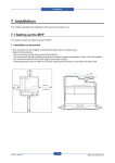
INSTALLATION
Note: For Right Angle & Crosscarrier assembly see
page 20. Open the stand carton first and assemble according to the instructions enclosed. Using two people,
center the folder on the stand as shown, fig. 3, with the
stand opening towards the front.
the rail guides, (fig. 4), and tighten the eccentric plate
locks, (fig. 6). Note both plates have two sets of locating holes in the plate rails. The first set is used when
the plate deflector is down, the other when the plate is
open, see fig. 5.
Do Not Lift
on Drive
Shaft
(round bar)
#1 Fold Plate/
Locating Pins
Notched
Plate Rail
(fig. 5)
(fig. 3)
2. Install the #1 (upper) foldplate, fig. 5.
Remove the parts of the folder checking them against
the packing list on page 3 of this manual. (Remove and
save the roller spacers on 820 only.)
Steps for assembling the Medalist folder:
(fig. 6)
3. Make sure the foldplate pins are located in the guide
rails, then lower the plate locks, (fig. 6).
Place the sound cover on top of the #1 foldplate. (the
sound cover is optional on 820 model).
(fig. 4)
1. Install the #2 (lower) foldplate. Lower the cover and
insert the #2 foldplate making sure the pins latch into
8
4. Install the feed table. Insert the table between the
F.669-D/820-870/Jan 98
Locating Pins/
Feeder Notch
(fig. 7)
side frames. Install the feed table so the notches in the
side brackets, (fig. 7), mate with the mounting pins inside the folder side frames.
(fig. 10)
7. Attach the stacker wheel assembly to the tie bar
next to the jam detector, as shown, fig. 10.
NOTE: Mounting pins should be located in the upper
set of threaded holes. (Lower holes are used to mount
a crossfold carrier assembly.)
Left Side
Locator
Hole
(fig. 11)
8. Using two people, position the compressor on the
bottom shelf of the stand, (fig. 11).
(fig. 8)
5. Install the stacker table assembly, (fig. 8), on the
back of the folder. Insert the spring-loaded end (right
side – viewed from rear of the folder) of the drive shaft
into the locator hole in the side frame, compress the
spring against the side frame and swing the opposite
end into position in the other side frame.
(fig. 9)
6. To pile folded materials, insert ears of stacker tray
into end of stacker table, as shown, fig. 9.
F.669-D/820-870/Jan 98
(fig. 12)
9. Install the strainer screen (shipped with the accessory kit) to the intake opening of the blower unit, (fig.
12).
9
Cleaning
A clean machine will reflect in the quality of the work it
produces. As you unpack your folder, wipe off any
excess protective oil, dirt, or dust which may have accumulated during shipping.
Keep your machine clean, and wipe off any
accumulations of paper dust at the end of each
day. Cover your machine anytime it is not in
use. See the maintenance section for additional cleaning instructions.
(fig. 13)
10. Connect the compressor hoses to the feed table
assembly. The sucker wheel hose threads through the
ty-rap and table support, underneath the feed table,
then onto the end of the sucker wheel shaft tube, as
shown in fig. 13.
NOTICE
820 ONLY: Whenever the machine is not being
used, reinsert the roller spacers shipped in the
machine to prevent flat spots from forming. This
is a operator controled maintenance function.
Roller flat spots are NOT COVERED under warranty.
CAUTION: DISCONNECT THE POWER BEFORE
INSTALLING THE ROLLER SPACERS.
Vacuum
Fitting
1. Close the deflectors on both fold plates.
2. Place one roller spacers at each side of the
feed table and feed between the rollers with
the hand wheel.
3. Remove the spacers before running the next
job.
Blower
Fittings
(fig. 14)
11. Attach the air hoses from the ends of the pile guides
to the double hose fittings of the blower. The single
hose from the sucker wheel fitting attaches to the
vacuum fitting, (fig. 14).
NOTE: Make sure all shipping plugs are removed
from the pump openings before attaching the
hoses!
10
F.669-D/820-870/Jan 98
Power Hookup
Control Panel
The standard Medalist Folder requires a 120 volt, 20
amp circuit with a three-prong, grounded receptacle.
It is the customer's responsibility to provide a power
line that meets all local electrical codes.
Speed
Sheet
Roller
Counter Counter Control
Motor Compressor
Reset
Motor
Optional 50 Hz, 240 volt machine draws 10 amps.
Provide proper circuit to handle load.
WARNING: DISCONNECT PROCEDURE:
NEVER PULL THE CORD to disconnect
the plug. Cord fatigue could lead to shorts
resulting in fire or personal injury from shock.
Always grasp plug body to disconnect power
cord, fig. 2, pg. 6.
WARNING: SHOCK HAZARD! NEVER
CUT THE GROUND LUG from a threeprong plug to fit a two-prong socket. Possible
shock could cause personal injury or death.
Hire a qualified electrician to provide a power
source that meets electrical requirements and
all local electrical codes.
(fig. 16)
The individual on/off switches for the compressor and
the roller motor are located on top of the roll guard cover,
(fig. 16, 870 model shown). They are marked with the
international ON (I) and OFF (O) symbols.
The rotary knob is the roller Speed Control.
The Sheet Counter window and the Counter Reset
button (optional on 820 models) are located on the far
left of this control panel (as viewed from the feed table).
Power Controls
Power Cord
Socket
Compressor
Power Cord
Power
Switch
(fig. 15)
The power panel, (fig. 15), is located on the back of
the folder below the first fold plate and stacker table.
The compressor unit power cord plugs into the socket
on the left side of the power panel.
Make sure the power switch is in the OFF ("O" or Open)
position. The external power cord plugs into the power
panel socket next to the switch.
F.669-D/820-870/Jan 98
11
OPERATION
Squaring
In order for your machine to fold stock squarely, it must
be fed into the rollers square. Your Medalist has been
adjusted at the factory and should only require periodic checks. The Medalist has a unique feed table adjustment feature to quickly and easily adjust it if needed.
WARNING: DISCONNECT THE POWER.
See power lockout procedure on page 6.
Table
Center
Mark
Feed Table
Squaring
Screw
3. Raise the sheet separator (ccw) so it is away from
the sucker wheel (fig. 19). Place a sheet of the paper
to be folded on the feed table. Slide the sheet forward
into the rollers. The sheet must contact the rollers
evenly and not touch the side guides. Turn the hand
wheel so about 1/2" (3mm) is pulled into the rollers.
4. Position the operator side guide so it is just touching
the sheet but not pushing it. The side guide must be
even to the sheet from end to end. Tighten the front
lock knobs then the rear knobs, (fig. 17 & 18).
5. Repeat step 4 on the nonoperator side guide.
Scale
Center
Line
6. The paper will now feed square into the rollers. Now
that the side guides are square, the feed table squaring screw, (fig. 17), can be adjusted for fine tuning the
overall squareness.
Vacuum Feed Sheet Separator
(fig. 17)
1. Adjust the feed table squaring screw and align the
center line of the scale with the center mark on the
feeder table, (fig. 17).
The sheet separator will have to be adjusted for the
weight of stock you are folding. Ideal adjustment will
feed only one sheet without marking the paper or feeding doubles. Use the following procedure to get started.
Fine tune these adjustments according to the condition of the paper and the environmental conditions of
your particular work area.
Adjustment procedure:
1. Raise the separator (ccw) to avoid marking the
sucker wheel.
NOTE: DO NOT MAKE SEPARATOR
ADJUSTMENTS WHILE THE FOLDER IS
RUNNING.
Front Guide
Adjusting
Knob
Scale
Side
Guides
(fig. 18)
2. Loosely position the feed table side guides to the
scales on the feed table, (fig. 17 & 18). Read the front
scale at the inside edge of the side guide clamp block.
The rear scale will line up with the inside edge of the
side guide. The scales are set up to center the paper
on the sucker wheel. Initially set each side guide 1/4"
(6mm) wide. Do not tighten the lock knobs.
12
Separator Guide
Adjusting Knob
Separator Guide
Plate
(fig. 19)
2. Turn the handwheel until the separator tip is positioned over a solid portion of the sucker wheel, i.e. between the rows of holes.
F.669-D/820-870/Jan 98
3. Place a one inch wide (25mm), double thickness
piece of stock to be folded under the tip of the separator plate, (fig. 19). Lower the separator (cw) until there
is a slight drag on the paper as it is pulled from under
the separator.
(2a)
Knob
(2b)
Knob
(ill. 1)
(ill. 2)
Feeding Paper
Vacuum
Advance
Backstop
(fig. 20)
4. The vacuum advance knob is located on the side of
the feed table, (fig. 20). Adjusting the knob will position
where the vacuum contacts the lift of paper, ill. 2a &
2b. Raising the knob will move the vacuum away from
the lift and toward the rollers (light papers). Lowering
the knob will move the vacuum contact toward the lift
and away from the rollers (heavy papers).
Horizontal Separator Adjustment
1. Raise the separator (ccw) to avoid marking the sucker
wheel.
1. Load a lift of paper onto the feed table. The lift should
be no higher than the side guides, 2" (51mm). Position
the backstop up against the lift, (fig. 20).
2. Turn on the air/vacuum pump. The air should float
the bottom of the lift approximately 1/16 to 1/8" (16 to
32mm). Air blast can be controlled by adjusting the
valve located at the end of each side guide, (fig. 21 &
fig. 22, pg 14).
Air Blast
Openings
Air Blast
Control
Knobs
2. Loosen knob (ill. 2). Setscrew in Accessory Kit,
(item #14, pg 67), may replace knob if desired.
3. As a starting reference, turn the handwheel until a
set of sucker wheel holes is at the 12 o’clock position.
4. Adjust separator assembly so that the plate is 1/16”
forward of the 12 o’clock position, measure from the
feed side of the plate.
(fig. 21)
5. Tighten knob (ill. 2).
F.669-D/820-870/Jan 98
13
There is a bleeder valve on the vacuum pump, (fig.
23), which allows for vacuum adjustment from completely off to completely on. General settings for the
bleeder valve are half open for 20# stock, and closed
for 80# and heavier stock. If your machine is feeding
doubles, this can be opened slightly to “relieve” some
of the vacuum and stop the double feeding.
Separator
Guide Lock
Set Screw
Air Blast
Openings
(fig. 22)
3. Turn the speed control to 1/2 or full speed. Place
your thumb on the back of the lift to keep paper from
feeding. Press the green rocker switch, the sucker
wheel will start to turn. Reduce the pressure of your
thumb to feed only 3 to 4 sheets. Press your thumb
down to stop the feeding again. Press the red rocker
switch to stop the sucker wheel from turning. If the paper
did not feed, adjust the position of the vacuum advance
(fig. 20, pg 13), bleeder valve (fig. 23), or sheet separator, (fig. 19, pg 12).
4. Check the accuracy of the 3 or 4 sheets fed. It may
be necessary to adjust the fold stop, (fig. 24), or the
squareness of the fold stop, (fig. 25, pg 15), or the
squareness of the side guides. Try only one adjustment at a time then repeat step 3.
5. If the folds look good, the job may now be run. The
speed of the folder will affect the accuracy of the folds.
Folds set up at slow speed will be different at high speed
and will need to be fine tuned.
Note: All of the controls mentioned above contribute to
smooth and accurate folding. There are many combinations possible depending on the condition of the paper and environment.
Fold Plates
Plate set up will depend on the type of stock and type
of fold you require. The fold plate design on the Medalist allows changing from open or closed deflector
(up and/or down folds) without removing or turning
the plates.
(ill. 3)
A good understanding of the roller/plate configuration
will help you decide which plate to open or close for up
or down folds. Illustration 3 shows the paper path for a
common Z-fold.
A self adhesive folding guide label is included with the
manual and may be conveniently placed on the delivery tray. Used along with scales on the fold plates, the
guide will help you quickly establish a rough set up for
some of the most common folding jobs.
Quick Setup
Scales (read at
these points)
Bleeder Valve (Vacuum Adjustment)
Inch/mm
Scale
Plate Stop
Bleeder Valve
(fig. 23)
14
(fig. 24)
Coarse adjustments are made by loosening the lock
screws on the plate stops, (fig. 24), then moving the
stop. The plate stop lines up with the scale marks along
its front edge (not where the paper contacts the stop).
Fine adjustments are made with the micro adjust knobs
on the ends of the fold plates, (fig. 25, pg 15).
F.669-D/820-870/Jan 98
Roller
Calipers
Micro-adjust
Knobs
(fig. 25)
(fig. 27)
Holding
Pin
To provide the proper clearance between rollers, 3/4"
wide paper strips are inserted into the calipers, (fig.
27). Simply press the caliper lever and insert the correct number of strips into the open gap. Put the same
number of strips into both sides of the folder. Do not
use folded or torn strips of paper (they may give false
(fig. 26)
For easy access to the second (bottom) fold plate while
making coarse adjustments (NOT WHILE RUNNING)
the feed table may be lifted out of the way and held
there by inserting the holding pin in the side frame,
(fig. 26).
Roller Caliper Set up (870 only)
WARNING: DO NOT MAKE ROLLER
ADJUSTMENTS WITH THE FOLDER
RUNNING! Serious personal injury or
machine damage could result from tools,
fingers, hair or clothing being caught by rollers.
Always disconnect the power cord when
setting rollers. Never operate folder with any
guards or fold plates removed.
Adjustable calipers are used on the Medalist 870 to
obtain clean crisp folds on a variety of stock. The
proper amount of paper strips (of the same material
being folded) in each caliper will give the best grip for
a good fold. As the paper is folded, the thicknesses of
the paper passing between the rollers increases. The
number of paper strips placed in the calipers should
be equal to the minimum thickness of the paper passing between the rollers (tail end of the sheet).
F.669-D/820-870/Jan 98
(ill. 4)
readings). Illustration 4 diagrams the position of rollers, fold plates, feed table, calipers and the correct
number of paper strips to be placed into the calipers
for a common "Z" fold.
The chart on page 16 shows the caliper and plate set
up for several common folds.
NOTICE
Whenever the machine is not being used, put
chipboard into the roller calipers in place of
paper to prevent rollers from getting flat spots.
This is an operator controlled maintenance
function. Roller flat spots are NOT COVERED
under warranty.
15
Roller Caliper Quick Set Up Guide
Roller calipers on the Medallist 870 feature quick set
up calipers. Calipers adjust the space or tension between rollers to provide the proper grip on the paper
for clean crisp folds. Each time the paper is folded, the
thickness increases. To compensate for this, the calipers on both sides of the machine have strips of paper
inserted. The correct number of paper strips to be
placed into the calipers corresponds to the tail end of
Fold Type
Letter
"Z"
Half
Double
Parallel
#1 Caliper
1
1
1
1
#2 Caliper
1
1
2
2
the sheet which will be the minimum thickness of the
stock passing between the rollers. Use 3/4" wide, cut
strips of the same material being folded. (Torn or folded
strips will give improper settings.) Make sure that the
calipers on both sides of the machine are set up with
exactly the same number of paper strips. The chart
below gives the set ups for calipers and plates for several common folds.
#3 Caliper
3
3
2
4
Stacker
The stacker consists of a table, belts, wheels, stacker
springs, and a delivery tray. The stacker accumulates
#1 Plate
open
open
open
open
#2 Plate
open
open
closed
open
4. Position the stacker springs on the slitter shaft tie
bar. They should be positioned towards the outside of
the sheet to hold the edges of the folded piece down,
(fig. 28). The springs may be bent for best operation.
5. Depending on the stock and the type of fold, best
stacking performance may be had by using just the
springs or the stacker wheels only. Fine tune these
adjustments as you run your job.
6. Loosen lower knob to adjust stacker wheels from
side to side.
Stacker
Wheels
Lower
Knob
Jam Detector
As standard equipment, all Medalist folders come
equipped with a delivery area jam detector, (fig. 29).
This device senses jams at the feed table and immediately stops the folder until the jam is removed and the
machine is restarted. The jam detector is mounted on
the center of the tie bar and looks similar to a third
stacker spring, it may be bent for best operation.
Stacker
Springs
(fig. 28)
folded stock for easy removal and stocking. The springs
and stacker wheels keep the delivered sheets from
opening up, interleaving and creating paper jams.
Set up:
1. Set the stacker wheels back from the slitter shaft the
width of the folded sheet plus an additional 1/4".
2. The wheels should be placed towards the center
of the folded piece to stop it in position as it is ejected
from the slitter assembly.
3. Center stacker belts under stacker wheels.
16
Jam Detector
(fig. 29)
F.669-D/820-870/Jan 98
NOTES
F.669-D/820-870/Jan 98
NOTES
17
SPECIAL APPLICATIONS
CAUTION: Use extreme care when handling and changing the
scoring or perforating blades. Severe lacerations could result
from careless handling procedures.
SLITTER ACCESSORIES
Stacker
Springs
Perf
Stripper
Perf
Collar
Wrenches
Rubber
Score
Wheel
Perf
Blade
Score
Blade
Blade
Holder
Slitter
Shaft
Score
Collars
Sliding
Collars
(fig. 30)
Your Medalist includes perforator and scoring blades,
two scoring collars, a rubber score wheel, a blade
holder and a grooved perf collar as standard equipment, (fig. 30).
Installation of accessory blades and collars is simplified by the removable slitter assembly, (fig. 31). Loosen
the set screw in the sliding collar, (fig. 31). Simply
slide the slitter shaft to the right, bring the opposite end
out of the folder frame and remove the shaft assem-
Set
Screws
(fig. 31)
bly. Install the accessory items as required and reinstall.
NOTE: Before tightening blade holder screws, mount
the holder with the blade loosely attached onto the slitter shaft. Now tighten the holder screws. This ensures the blade is concentric with the slitter shaft making for easier installation and even scores and perfs.
Scoring
Position your scoring blade as desired. Scores should
be made so that the blade runs on the side of the sheet
that will be on the inside of the finished fold. Scores
may be made on the Medalist in two ways;
1. The blade may be run on top of the
rubber scoring wheel supplied. The
rubber wheel is simply positioned on
the slitter shaft opposite the score
blade.
2. For a more controlled fold as might
be needed with various stock thicknesses, use the scoring collars on the
shaft opposite the score blade, (ill. 5).
Position the collars on either side of the
scoring blade. The degree of score desired may be
obtained by moving the collars either closer or farther
away from the blade.
Score Blade
Score Collars
Scoring
18
(ill. 5)
F.669-D/820-870/Jan 98
Perforating
Perforating may be used to deliver a perforated sheet flat or as a guide for
additional right angle folds.
*NOTE: A stripper is required for each perforator blade.
Stripper*
Adjusting
Screw
Perforator Blade
Perforator Collar
(ill. 6a)
Perforating
The perforating blade (and any additional blades purchased in addition to the
one supplied) is mounted on the upper shaft of the slitter assembly. The perforating blade is run against the inside edge of the groove in the perforating collar
mounted on the lower shaft, (ill. 6a).
The curved slotted stripper finger is mounted on the square tie bar above the
slitter assembly with one finger on either side of the perf blade. The stripper
finger prevents the paper from wrapping around the perf wheel. It may be adjusted by loosening the button head screw in the mounting bracket and moving
the fingers up or down, (ill. 6a). The fingers should be adjusted as close to the
blade as possible without rubbing on it. Contact with the holder will cause premature wear of the stripper fingers.
Slitting
With the addition of a pair of slitting blades, folded sheets may be cut apart after
folding or before delivery to a right angle cross carrier. Slitting blades are
Slitting Blades
Scoring
(ill. 6b)
attached in the same manner as perforating blades. Note that blades are mounted
to blade holders with special flathead countersunk screws. Mount the blade/
holder unit onto the upper shaft in the position the slit is to be made. Position the
second blade/holder onto the lower slitter shaft as shown in illustration 6b above
so that the flat edges of the blades fit together snug (too much space will give
ragged cuts). Slitting blades may also be installed to run against a collar as
shown in the perforating instructions.
F.669-D/820-870/Jan 98
19
RIGHT ANGLE CROSSFOLD SYSTEM
(fig. 32)
Challenge offers a Right Angle Crossfold System which
is used in conjunction with the Medalist
The System consists of a second parallel unit, a crossfold carrier table, shorter stand and a transfer assembly which displaces the delivery table of the folder (the
delivery table is placed on the back of the crossfolder).
CAUTION: Disconnect the power to all
units before positioning the crossfold system and making the electronic connections.
Button
Button Head
Head
Mounting Screws
Screws
Mounting
Support
Support
Leg
Leg
Leveling
Screw
Installation
1. Remove the stacker wheel assembly and delivery
table from your folder. See note on page 70.
2. Reposition the folder on its stand. Move the folder to
the back edge of the stand as shown in the photo above,
fig. 32.
(fig. 33)
Use LOWER hole
for Crosscarrier
Mounting Pin
3. Place the folder for the crosscarrier onto its stand. It
should also be positioned towards the back edge of its
stand as shown in fig. 32.
4. Install the cross carriage support legs to the cross
carriage frame, (fig. 33). The legs are mounted with
two, #10-24 x 3/8" button head cap screws.
5. Insert the crosscarrier assembly between the side
frames making sure the support legs rest on the crosscarrier stand. Make sure the mounting pins for the
crosscarrier conveyor assembly are in the lower set of
holes in the roller side frames, (fig. 34). Install the left
hand screw first, then the right hand side.
20
(fig. 34)
A little downward pressure on the crosscarrier assembly will help to align the holes to aid installing the mounting screw (the friction drive is located under the right
side requiring the pressure to align the mounting holes).
F.669-D/820-870/Jan 98
NOTE: If you have purchased a crosscarrier kit
as an after market addition to convert a second
folder to a right angle, you will need to perform
three additional procedures (A – C) as follows.
C. Install the electronic pigtail assembly so the machines can electronically communicate with each other.
Instructions for making this hookup can be found on
pages 72 & 73 in the Parts and Assembly Drawings
section of this manual.
6. Once the crosscarrier legs have been attached and
the crosscarrier installed into the parallel unit, level the
crosscarrier by adjusting the leveling screws attached
to the bottom of the support legs, (fig. 33, pg 20).
NOTE: The carrier must be level side-to-side so it is
level with the fold rollers. End-to-end, it does not have
to be level, adjusting screws need only to be set low
enough to provide enough contact between the friction
drive collars (fig. 35) to drive the crosscarriage rollers.
Friction Drive
Collars
7. Reposition the delivery table and stacker wheel assembly from the folder to the back of the right angle
parallel unit.
(fig. 35)
A. Reposition the O-ring friction drive collar from
the center (feed table) position to align with the drive
collar of the cross carrier, (fig. 35). Loosen the set
screws in the collar and move the collar to the right
until it aligns with the collar on the crosscarrier. O-rings
should alternate contacts. Retighten the set screws.
Drive Gear
(fig. 37)
1/4”
Slitter Shaft
Transfer
Table
(fig. 36)
B. Install a transfer table drive gear onto the lower
slitter shaft of the machine that is to be used as the
main folder. Remove the lower slitter shaft and remove all the drive wheels (and any perf, score, or slitting blades/wheels). Install the drive gear (teeth first)
onto the shaft, position and secure 1/4" from the end of
the shaft, see fig. 36. Replace the drive wheels (and
any accessory wheels, blades, or collars). Replace the
scoring shaft into the folder. (Gear may be repositioned
on the shaft if necessary once the transfer table has
been installed.) Make sure all the set screws are tightened securely.
F.669-D/820-870/Jan 98
8. Position the transfer table onto the back of the folder.
It mounts in the same manner as the delivery table —
Insert the spring loaded end (right side when viewed
from the rear of the folder) of the drive shaft into the
locator hole in the side frame, compress the spring
against the frame and swing the opposite end into position in the other side, (fig. 37). NOTE: Make sure the
drive gears mesh as shown in fig. 36.
9. Position the crosscarrier right angle unit against the
back of your folder as in figure 32, pg 20 and proceed
to make your conveyor and fold plate adjustments.
10. Connect the electrical cable pigtails protruding
above the electrical panels. This allows the folders to
communicate and shut down simultaneously in case
of a paper jam in one or the other unit.
11. Connect the power cord into the back of the power
panel. Plug the cord into a 20 amp grounded receptacle.
21
12. Turn on the Right Angle Crossfold Unit FIRST.
(When connected as a Crossfold System, the Right
Angle Crossfold unit is the master and must have the
power turned on first.)
†
If you have purchased the Crossfold System as an
addition to your folder, you may have to add the pigtail
cable connector to the electrical panel of your existing
folder. The instructions for making this connection are
located in the back of this manual beginning on page
72.
Conveyor Set Up
Take a folded sample of stock coming off the transfer
table and insert it into the marble guide. Position the
marble guide of the crosscarrier conveyor carefully so
that the folded sheets land under the bevelled edge of
the holder. You will probably need to position the guide
plate to help guide the paper under the marble guide.
Glass
Metal
Plastic
(fig. 38)
Push a sample sheet through by hand until it butts the
fold rollers. Adjust the angle of the guide so the stock
enters the rollers squarely. When running, the angled
position of the rollers will pull the paper under the
marbles and against the guide to align the stock for
delivery into the fold rollers.
Your crosscarrier comes with three types of marbles,
glass, steel, and plastic, (fig. 38), to provide different
amount of holder pressure. Typically, heavier marbles
are used closer to the rollers to provide more guiding
action.
Fold plate set up is identical to the folder (see pg. 14).
NOTE: Crosscarrier systems are factory set up to
fold 90° to the left as it exits the folder. If it is
necessary to fold 90° to the right, a simple kit is
available from the factory to switch the direction
of the crosscarrier. Contact your authorized
Challenge Dealer for details. Instructions and
parts included in the kit are as noted on the
following pages.
22
F.669-D/820-870/Jan 98
OPTIONAL CROSSFOLD CONVERSION KIT 35537
CAUTION: Turn off the power to all units
and disconnect the power cords before
disassembling or making any electronic connections.
Standard
LH
Delivery
A
B
Marble
Holder
Marble
Holder
Shaft
Shaft
Mounting
Block
Set
Screws
Shaft
Mounting
Block
Drive Belt
Covers
(fig. 39)
Converted
Optional
RH
Delivery
C
6. Remove the taper plates.
(ill. 7)
Ref.
A.
B.
C.
d.
e.
f.
Crossfold Conversion Kit 35537
Part No.
Description
A
35514 Marble Holder Assembly–RH............1
(Assembly includes items d–f below)
35533 Cover, RH Roller Belt........................1
35534 Cover, LH Roller Belt.........................1
E-1172-20 Bushing (Marble Holders).............20
H-6881-408 1/4-20x1/2" Hex Screw (Plastic)..2
H-6412-4 1/4-20 Hex Nut (Plastic)...................2
In order to have your right angle crossfold machine
carry to the right as it exits the folder, the crosscarrier
is used with simple repositioning of components. No
additional drilling or tapping of holes is required. A few
parts contained in the conversion kit will have to be
exchanged. Reference numbers in the instructions
refer to parts in drawing at bottom of page 24.
INSTRUCTIONS TO REPOSITION THE ROLLER
ASSEMBLY FOR RH DELIVERY TO THE RIGHT
ANGLE PARALLEL UNIT.
1. Remove any hold-downs or deflectors from the
crossfold assembly.
2. Remove all the marbles from the marble holder.
3. Loosen and remove the mounting screws holding
the crosscarrier assembly to the parallel unit and take
it off the machine.
4. Remove the marble holder assembly by loosening
the setscrews in the marble holder shaft mounting
blocks, (fig. 39).
5. Remove the belt cover guards (held with one screw
in the middle of the frame).
F.669-D/820-870/Jan 98
B
Qty
(fig. 40)
7. Remove the marble holder shaft mounting blocks
(2) from their original “A” position and reinstall them to
the “B” position, fig. 40.
8. Remove the entire roller assembly by loosening the
mounting screws (4 on each side) that hold the roller
mounting rails to the frame.
Roller
Drive
Plate
(bottom
view)
A
B
A
B
B
A
A
B
(fig. 41)
23
9. Remove the four (4) screws, (fig. 41, pg 23), mounting the roller drive blocks and reposition from the “A”
mounting holes to the “B” holes (ill. 8, INSET A).
10. Grasp the roller assembly mounting rails and while
turning the rollers slightly, shift the assembly so that
the rollers are positioned at the opposite angle as shown
in illustration 7.
11. Reassemble the cross carrier assembly to the frame
by mounting in the appropriate holes.
12. Taper plates should be flipped end to end and remounted to the crosscarrier frame. (NOTE: The mounting blocks (ill. 8, ref. #10) supporting the wide end of
the taper plates will have to be removed and remounted
onto the opposite side of the frame.)
Replace the factory installed LH marble holder
assembly with the RH part supplied in the kit.
Set Screw &
Mounting Screw
Marble Holder
Mounting
Shaft
Guide Block
Mounting Arm
Squaring Knob
Spring, Wing Nut
(fig. 42)
13. Remove the marble holder mounting shaft.
14. Remove the squaring assembly hardware: squaring knob, wing nut, and spring, (fig. 42).
15. Remove the original LH marble holder by loosening the setscrew and removing the mounting screw,
(fig. 42). Reassemble with the new RH marble holder.
16. Remove the marble shaft guide block (ill. 8, ref.
#22), rotate it 180°, and reassemble to the marble
holder mounting arm (ref. #23).
17. Replace the squaring assembly hardware removed
in step number 14 & 15 above.
18. Slide the marble holder mounting shaft through the
guide block and reassemble to the shaft mounting
blocks on the edges of the crosscarrier frame.
19. Adjust the plastic support screws (ill. 8, ref. #41)
on the ends of the marble holder so the holder is level
and does not touch any of the rollers. Lock into position with the plastic lock nuts (ref. #42).
20. Position the new drive belt covers (ill. 8, ref. #50 &
51) from the kit over the ends of the crosscarrier rollers, (fig. 39). Secure with the single button head screw
(ref. #38).
21. Reinstall the crosscarrier assembly into the parallel unit. Follow the Right Angle Crossfold Installation
Instructions on page 20 to position the reoriented crossfold system behind the Medalist folder and make all
electrical connections as instructed.
(ill. 8 - drawing appears for instructional
reference only, see page 68/69 for enlarged
drawing & parts list)
24
F.669-D/820-870/Jan 98
MAINTENANCE
Cleaning
Take a few minutes at the end of each day to wipe off accumulations of paper dust. Cover your machine when
not in use. These practices will keep your machine clean and in tip-top operating condition.
Rollers
Keep fold rollers clean. Most folding problems are the result of material accumulations on the fold rollers.
Although designed to minimize accumulations, over a period of time, ink and dust buildup will prevent the rollers
from gripping the stock evenly. Rollers must be cleaned on a regular basis to maintain optimum
folding performance.
WARNING: Always disconnect the power cord before cleaning! Rollers have a strong grip.
Keep tools, clothing, hair and cleaning rags away from rollers. Severe injuries and machine
damage could result from items being caught in rollers. Do not operate folder with guards or fold
plates removed.
Disconnect the power, remove the fold plates and clean rollers with blanket wash (not type wash) or a commercial product designed for the type of rollers your machine is equipped with. Turn the rollers with the handwheel
never attempt to clean rollers with the machine running – see Warning above.
Check rollers periodically for wear. During normal use fold rollers will gradually wear. Worn rollers will be evident
by increased setup times, increased spoilage, inaccurate folding, and inability to control the sheet. If one or more
of these conditions are noted, contact your authorized Challenge folder dealer to inquire about inspection and/or
possible roller replacement.
Vacuum Pump–Compressor
Filters – Because the printing process produces large
amounts of paper dust as well as offset powder, regular
inspection and cleaning of pump filters is an important
part of folder maintenance. Filters should be removed,
(fig. 43), and blown out at least weekly, more if you are
running large, long-run jobs. Filters should be washed
periodically with a cleaning solvent and dried thoroughly
before replacement.
If filters become difficult to clean or deteriorate, they
should be replaced immediately. Replace any filters
which become contaminated with oil or grease.
Filter Caps
Pump Vanes – To prevent dirt and dust buildup from
causing the pump vanes to stick or break, the pump
should be flushed periodically. Use a nonflammable
safety solvent. Remove the hoses, disconnect the filters and pour several teaspoons of solvent through
the intake into a rag held over the opposite side.
(fig. 43)
Pump Lubrication – Your Challenge folder uses an oil-less pump and motor. Do Not Attempt to lubricate the
pump or motor.
F.669-D/820-870/Jan 98
25
MAINTENANCE
(CONTD.)
General Inspection
All moving parts are subject to wear. Periodic inspection will avoid machine failure in the middle of critical job
runs. Inspection should cover the following list of items:
Hoses – Inspect for cracks and leaks. Replace as necessary.
Drive Belts – All belts stretch and wear. Check and replace as necessary. Keep replacement parts on hand.
Register Tapes and Stacker Belts – Check for signs of wear, alignment, and proper tension. Schedule replacement before they fail on a critical job.
Rubber Wheels – Pullout tires, scoring wheels, and stacker wheels should be inspected also. Make sure they
are in good condition to insure consistent delivery of folded pieces, consistent stacking, and accurate folds. Keep
extra score wheels on hand and make sure stacker wheels rotate freely.
DC Motor Brushes – Motor brushes should be inspected approximately every three months. If worn to 1/4"
(7mm) or less replace the brushes.
Lubrication
To ensure long life, lubricate your machine weekly or after every 8 hours of use. The best time to lubricate your
machine is early in the week before start-up. This allows the lubricants to work into the parts as the machine is
operated rather than simply running off. Oil and grease locations are listed below.
For oil locations, use a Non-Detergent, #30 weight oil or approved equivalent. Be careful not to over-oil. Oil left on
rollers will cause them to swell, which will interfere with folder performance. For grease locations use Amoco
Amalith #2 (Challenge Part #6614) or approved equivalent. Wipe off any excess.
Oil Locations:
Sucker Drive Shaft Bearings
All Roller Bearings
Stacker Drive Shaft Bearings
Caliper Assembly Bearings
?
?
?
?
Grease Locations:
?
All Roller Gears
?
Slitter Drive Gears
?
Slitter & Handwheel Needle Bearings
Model 820
page 30, ref. no. 60
Not Applicable
page 32, ref. no. 40 & 17
Not Applicable
Model 870
page 36, ref. no. 59
page 36, ref. no. 64
page 38, ref. no. 40 & 17
page 36, ref. no. 64
page 32, ref. no. 1
page 30, ref. no. 32 & 68
page 28, ref. no. 37
page 30, ref. no. 28
page 32, ref. no. 32
page 38, ref. no. 1
page 36, ref. no. 30 & 65
page 34, ref. no. 36
page 36, ref. no. 26
page 38, ref. no. 32
NOTE: The vacuum-pump unit is of an oil-less type. Do not attempt to lubricate the pump or motors.
Service
Authorized Challenge Dealers are located throughout the United States, Canada and the world. They have
factory-trained service personnel on staff to handle all your service needs. Call 1-616-842-8300 for the dealer
nearest you.
26
F.669-D/820-870/Jan 98
NOTICE
The instructions on the
following pages are for the
use of trained service
personnel only!
Attempting to perform
repair and replacement
procedures without proper
training may cause machine
damage or operator injury!
PARTS CUSTOMERS: The Challenge Machinery Company provides parts with the express understanding that they are to replace parts found missing or no longer serviceable on equipment designed
and/or manufactured by Challenge. The Challenge Machinery Company assumes no liability for any
modification or alteration to any Challenge products, and any such modification or alteration to any
Challenge products is not authorized by The Challenge Machinery Company. Any modification or
alteration of any Challenge product will void any remaining warranty.
F.669-D/820-870/Jan 98
27
28
F.669-D/820-870/Jan 98
MODEL 820 MAIN ASSEMBLY - Left Hand Side
35300 SHEET 1 OF 3
F.669-D/820-870/Jan 98
29
MODEL 820 MAIN ASSEMBLY - Left Hand Side
35300 SHEET 1 OF 3
30
F.669-D/820-870/Jan 98
MODEL 820 MAIN ASSEMBLY - Right Hand Side
35300 SHEET 2 OF 3 REV ‘C’
F.669-D/820-870/Jan 98
31
MODEL 820 MAIN ASSEMBLY - Right Hand Side
35300 SHEET 2 OF 3 REV. ‘C’
32
F.669-D/820-870/Jan 98
MODEL 820 MAIN ASSEMBLY - Front View
35300 SHEET 3 OF 3
F.669-D/820-870/Jan 98
33
MODEL 820 MAIN ASSEMBLY - Front View
35300 SHEET 3 OF 3
34
F.669-D/820-870/Jan 98
MODEL 870 MAIN ASSEMBLY - Left Hand Side
35450 SHEET 1 OF 3
F.669-D/820-870/Jan 98
35
MODEL 870 MAIN ASSEMBLY - Left Hand Side
35450 SHEET 1 OF 3
36
F.669-D/820-870/Jan 98
MODEL 870 MAIN ASSEMBLY - Right Hand Side
35450 SHEET 2 OF 3 REV. ‘A’
F.669-D/820-870/Jan 98
37
MODEL 870 MAIN ASSEMBLY - Right Hand Side
35450 SHEET 2 OF 3 REV. ‘A’
38
F.669-D/820-870/Jan 98
MODEL 870 MAIN ASSEMBLY - Front View
35450 SHEET 3 OF 3
F.669-D/820-870/Jan 98
39
MODEL 870 MAIN ASSEMBLY - Front View
35450 SHEET 3 OF 3
FOLDPLATE ASSEMBLY #1
35061 REV. ‘C’
40
F.669-D/820-870/Jan 98
FOLDPLATE ASSEMBLY #1
35061 REV. ‘C’
F.669-D/820-870/Jan 98
41
FOLDPLATE ASSEMBLY #2
35080 REV. ‘D’
42
F.669-D/820-870/Jan 98
FOLDPLATE ASSEMBLY #2
35080 REV. ‘D’
F.669-D/820-870/Jan 98
43
FEEDER ASSEMBLY
35100-2 REV. ‘F’
44
F.669-D/820-870/Jan 98
FEEDER ASSEMBLY
35100-2 REV. ‘F’
F.669-D/820-870/Jan 98
45
STACKER ASSEMBLY
35128-1
46
F.669-D/820-870/Jan 98
LONG STACKER ASSEMBLY
(OPTIONAL)
35290-1
F.669-D/820-870/Jan 98
47
STACKER WHEEL ASSEMBLY
35198 REV. ‘E’
48
F.669-D/820-870/Jan 98
CALIPER ASSEMBLY
35041
F.669-D/820-870/Jan 98
49
MEDALIST STAND ASSEMBLY
35470 REV. ‘C’
50
F.669-D/820-870/Jan 98
RIGHT ANGLE STAND ASSEMBLY
35473 REV. ‘C’
F.669-D/820-870/Jan 98
51
JAM DETECTOR ASSEMBLY
EE-2607 REV. ‘C’
52
F.669-D/820-870/Jan 98
ELECTRICAL SEQUENCE OF OPERATION
ELECTRICAL SEQUENCE OF OPERATION
A. Close the POWER switch.
B. Press the compressor ON switch.
C. Press the START button.
D. Adjust the SPEED CONTROL.
ELECTRICAL SCHEMATIC REFERENCES
(Drawings E-2657 & E-2658)
While the POWER switch is closed, power is brought to the transformer, provided the 8A fuse is conductive. The
transformer provides power to the start/stop circuit, and to the sheet counter. Opening the main disconnect
switch at any time cuts power to the transformer.
When the compressor ON switch is closed, power is brought to the compressor.
When the START switch is closed, the folder motor relay coil K will energize, provided the jam detector switch,
the rear guard switch, the emergency stop switch (opt.), and the stop switch are closed. Power is then supplied
to the folder motor, provided the 3.15A fuse is conductive. The relay coil K remains energized until any of the
above listed switches are opened.
The speed of the folder motor can be adjusted by turning the SPEED CONTROL knob.
F.669-D/820-870/Jan 98
53
54
F.669-D/820-870/Jan 98
820 BASIC MACHINE SCHEMATIC - (120 VOLT)
E-2781
F.669-D/820-870/Jan 98
55
820 BASIC MACHINE SCHEMATIC - (230 VOLT)
E-2782
56
F.669-D/820-870/Jan 98
870 BASIC MACHINE SCHEMATIC - (120 VOLT)
E-2657 REV. ‘A’
F.669-D/820-870/Jan 98
57
870 BASIC MACHINE SCHEMATIC - (230 VOLT)
E-2658 REV. ‘A’
58
F.669-D/820-870/Jan 98
820/870 BACK COVER PLATE ASSEMBLY - (120 VOLT)
EE-2655 REV. ‘C’
F.669-D/820-870/Jan 98
59
820/870 BACK COVER PLATE ASSEMBLY - (120 VOLT)
EE-2655 REV. ‘C’
60
F.669-D/820-870/Jan 98
820/870 BACK COVER PLATE ASSEMBLY - (230 VOLT)
EE-2656 REV. ‘B’
F.669-D/820-870/Jan 98
61
820/870 BACK COVER PLATE ASSEMBLY - (230 VOLT)
EE-2656 REV. ‘B’
62
F.669-D/820-870/Jan 98
820 CONTROL PANEL ASSEMBLY
EE-2780
F.669-D/820-870/Jan 98
63
870 CONTROL PANEL ASSEMBLY
EE-2654 REV. ‘B’
120/220 VOLT PUMP ASSEMBLY
PP-270/PP-274
22 21
15
20
1
19
2
3
16
27
28
18
17
4
5
24
25
6
14
13
12
23
7
8
9
10
11
64
F.669-D/820-870/Jan 98
120 VOLT 60 HERTZ PUMP ASSEMBLY
PP-270
220 VOLT 50 HERTZ PUMP ASSEMBLY
PP-274
F.669-D/820-870/Jan 98
65
STANDARD ACCESSORIES
AA-11214
2
1
4
8
11
12
5
10
13
6
7
66
9
3
F.669-D/820-870/Jan 98
STANDARD ACCESSORIES
AA-11214
NOTE:
If desired item #14 replaces knob (item #20, pg 44).
F.669-D/820-870/Jan 98
67
68
F.669-D/820-870/Jan 98
CROSS CARRIAGE ASSEMBLY
35500 REV. ‘D’
F.669-D/820-870/Jan 98
69
CROSS CARRIAGE ASSEMBLY
35500 REV. ‘D’
70
F.669-D/820-870/Jan 98
TRANSFER ASSEMBLY
35550 REV. ‘F’
F.669-D/820-870/Jan 98
71
TRANSFER ASSEMBLY
35550 REV. ‘F’
CROSSFOLD ELECTRICAL HOOK-UP
K-2670-i
72
F.669-D/820-870/Jan 98
CROSSFOLD ELECTRICAL HOOK-UP INSTRUCTIONS
WARNING: Shock Hazard! Disconnect and
lockout the power to both machines before
proceeding with the following instructions.
Crossfold Folder Power Panel Connections
(Steps 1-4)
1. Remove the power panel of the crossfold machine.
(There is enough wire to lay the panel down flat in front
of the machine.)
2. From the kit, locate the pigtail labeled “A” (item #2 in
the drawing on the opposite page). Insert the wire end
of the pigtail through the hole in the top of the power
panel housing.
3. Connect the wires to the terminal strip as shown in
the CROSSFOLD FOLDER POWER PANEL detail in the drawing on the opposite page.
Operation - Crossfold System
To run the two machines together as a Right Angle
Crossfold System, turn off the power to both machines.
Position the two machines together and connect the
Crossfold Jumper Assembly (item #1 in the drawing
on the opposite page) to the pigtails installed in the
power panels.
Turn on the Right Angle Crossfold Unit FIRST. (When
connected as a Crossfold System, the Right Angle
Crossfold unit is the master and must have the power
turned on first.) Make any operational setup and adjustments as described in the operating section of this
manual.
Operation - Independent Folding Units
4. Double check the wiring connections against the
drawing and when it is correct, replace the power panel.
Parallel Folder Power Panel Connections
(Steps 5-9)
5. Remove the power panel of the parallel machine.
(There is enough wire to lay the panel down flat in front
of the machine.)
6. From the kit, locate the pigtail labeled “b” (item #3 in
the drawing on the opposite page). Insert the wire end
of the pigtail through the hole in the top of the power
panel housing.
To run the two machines independently of each other,
disconnect the power and remove the Crossfold
Jumper Assembly. Install the Terminator Jumper Plug
(item #4, opposite page) to the pigtail of the Parallel
Folder. Now the Parallel Unit and the Crossfold Unit
may be operated independent of each other (Crossfold Unit does not require a terminator).
WARNING: Always disconnect the power
to both folding units before making
jumper or terminator connections.
7. Locate the Jam Detector Cable and trace wire #36
to the terminal strip. Remove wire #36 from the terminal strip and using the wire nut supplied in the kit, connect this wire (#36 from the Jam Detector) to wire #36A
of the pigtail.
8. Connect wire #36B of the pigtail to the terminal strip
at the position from which wire #36 of the Jam Detector was just removed.
9. Double check the wiring connections for the PARALLEL FOLDER POWER PANEL against the drawing on the
opposite page and when they are correct, replace the
power panel.
F.669-D/820-870/Jan 98
73
IMPOSITION MANUAL
Some of the most common impositions are illustrated
in the next pages. These appear for reference only and
do not imply suitability or practicality.
To assist you in planning any folding job, first fold a
“Dummy” by hand. Use the most logical layout to avoid
unnecessary folding problems such as air pockets and
adverse grain effects. If the stock or imposition is unusual, try running a sample on the folder BEFORE
PRINTING.
In order to use this imposition guide correctly,
it is necessary to refer to the plates in each section
as follows:
Parallel Plates - #1 (up fold)
#2 (down fold)
Crosscarrier - #1 (up fold)
#2 (down fold)
When planning a form, check your folded “Dummy”
for proper page numbers and correct guide edges.
As illustrated, the sheets are visualized lying on the
feed table. The end toward the rollers is marked
“HEAD.” Illustrations of the folded product are shown
as delivered to the delivery table.
The numbers on the illustrations indicate the page
number of the final folded product. Page numbers within
circles indicate the page numbers on the side which
woukd face down on the feed table. Letters are used
instead of numbers for pieces without distinct pages.
When folded, letter surfaces will be face-to-face.
NOTE: No responsibility, either direct or assumed, is
indicated for errors in these examples - Double Check
Your Folded Dummy!
FOUR PAGE
SIX PAGE ACCORDIAN
Use Plates: Parallel - #1
Use Plates: Parallel - #1
#2
May be folded two or more up and slit apart
Use Plates: Parallel - #1
#2
May be folded two or more up
and slit apart
May be folded two or more up
and slit apart
5
1
4
6
HEAD
Use Plates: Parallel - #1
#2
B
A
HEAD
EIGHT PAGE STEP FOLD
3
A
3
2
GATEFOLD (Open)
2
B
4
1
B
A
A
B
74
HEAD
May be folded two or more up
and slit apart
F.669-D/820-870/Jan 98
8
1
2
8
HEAD
7
3
3
4
4
6
6
5
5
1
Use Plates: Parallel - #1
Right Angle - #1
2
EIGHT PAGE RIGHT ANGLE
Use Plates: Parallel - #1
Right Angle - #1
C
B
16
1
8
A
B
7
10
15
HEAD
4
3
A
13
14
B
11
C
12
HEAD
6
A
5
F.669-D/820-870/Jan 98
2
A
Use Plates: Parallel - #1
Right Angle - #1
- #2
C
SIXTEEN PAGE,FOLD
Use Plates: Parallel - #1
Right Angle - #1
- #2
B
TWELVE PAGE, LETTER FOLD (HEADS OUT)
C
8
5
HEAD
7
6
HEAD
4
3
9
10
12
Use Plates: Parallel - #1
Right Angle - #1
- #2
1
Use Plates: Parallel - #1
- #2
Right Angle - #1
11
TWELVE PAGE,LETTER FOLD ACCORDIAN
2
TWELVE PAGE BOOK, SADDLE STITCH
9
HEAD
EIGHT PAGE 2 R A OBLONG
7
THE FOLLOWING LAYOUTS REQUIRE THE USE OF THE CROSSFOLD SYSTEM
(DESIGNATED BY ‘Right Angle’ IN THE ILLUSTRATIONS BELOW).
75
76
F.669-D/820-870/Jan 98
5
3
7
2
8
1
Roller Bracket Assemblies
(for reference only)
6
SLITTER SHAFT ASSEMBLY COMPONENTS
(Two Assemblies Used Per Machine)
AA-35009
4
7
F.669-D/820-870/Jan 98
77
SLITTER SHAFT ASSEMBLY COMPONENTS
(Two Assemblies Used Per Machine)
AA-35009
ROLLER REPLACEMENT REPAIR KITS
870 COMBO ROLLER REBUILD KIT: K-35294
Qty.
P/n
Combo rollers
Roller gears
Gear keys
Idle roller bushings
Main roller bushings
Sucker wheel belt
“O” Ring drive belt
Out feed tires
Tech notes
4
4
4
6
2
2
5
4
1
35055
35052
H-6121-604
A-10257-5
35029
35113
35179-1
A-10249
MFG-016
NOTE: ROLLER/PLATE GAUGES ARE HIGHLY
RECOMMENDED WHEN INSTALLING A ROLLER REBUILD KIT.
ROLLER/PLATE GAUGE KIT: K-35292
Plate gauge
Spacer bar #3 Roller
Tech notes
2
1
1
A-10471
35289
MFG-016
“CHALLENGE WILL NOT ACCEPT RETURN OF
SUGGESTED PARTS NOT USED IN A REBUILD”
870 RUBBER ROLLER REBUILD KIT: K-35293
Rubber rollers
Roller gears
Gear keys
Idle roller bushings
Main roller bushings
Sucker wheel belt
“O” Ring drive belt
Outfeed tires
Tech notes
4
4
4
6
2
2
5
4
1
35051
35052
H-6121-604
A-10257-5
35029
35113
35179-1
A-10249
MFG-016
820 ROLLER REBUILD KIT: K-35298
Rubber rollers
Roller gears
Gear keys
Idle roller bushings
Main roller bushings
Roller spring
Sucker wheel belt
“O” Ring drive belt
Outfeed tires
Tech notes
78
4
4
4
6
2
6
2
5
4
1
35051
35052
H-6121-604
35283
35029
7922
35113
35179-1
A-10249
MFG-016
F.669-D/820-870/Jan 98
NOTES
F.669-D/820-870/Jan 98
79
© 1996 by The Challenge Machinery Company. All rights reserved. Printed in the U.S.A.
F.669-D/820-870/Jan 98