1
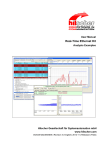
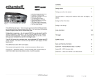
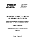
12843 Foothill Blvd. Suite C
Sylmar, California 91342
V: 818.898.3380
F: 818.898.3360
[email protected]
GTP - 32
CONTROL PROCESSOR
User Manual
REV 2 UNITS
- 1-
TABLE OF CONTENTS
INSTALLATION ........................................................................................................... 4
CONFIGURATION ...................................................................................................... 5
IP ADDRESS SETUP ................................................................................................. 5
SUBNET MASK SETUP ............................................................................................ 5
GATEWAY ADDRESS SETUP ................................................................................. 5
ETHERNET LINK SPEED SETUP ............................................................................ 6
SETUP ........................................................................................................................... 6
SET PASSWORD .................................................................................................... 7
SET SYSTEM LABEL .............................................................................................. 8
SET SYSTEM TIME .............................................................................................. 10
GPI ............................................................................................................................... 11
GPO ............................................................................................................................. 14
SERIAL/ETHERNET CHANNEL SETUP ................................................................... 16
Serial/Ethernet Protocol Assignment ............................................................ 16
Serial/Ethernet Device Configuration ........................................................... 17
Serial Physical Configuration........................................................................... 18
Ethernet Physical Configuration ..................................................................... 19
EVENT NOTIFICATION ........................................................................................... 19
EVENT DEFINITIONS ............................................................................................. 20
USP EVENTS ......................................................................................................... 20
REMOTE EVENT DEFINITIONS ........................................................................ 22
COMBINATORIAL EVENTS ................................................................................ 24
ACTION DEFINITIONS ........................................................................................... 30
TIME ACTIONS ..................................................................................................... 30
GROUP ACTIONS ................................................................................................. 32
EVENT MONITORING ............................................................................................. 34
BACKUP AND RESTORE TABLES ........................................................................ 38
EVENT LOGGING ..................................................................................................... 40
SPECIFICATIONS .................................................................................................... 43
FRONT & REAR VIEWS .......................................................................................... 47
CONFIGURE GPIS FOR DRY/WET OPERATION .............................................. 48
CONFIGURE GPOS FOR DRY/WET OPERATION ............................................. 50
LIMITED WARRANTY .............................................................................................. 51
- 2-
REVISION HISTORY
2.0
2.1
First Draft of combined Installation and Setup Manual
Protocol Assignment Table Setup added.
- 3-
INSTALLATION
CAUTION
Do NOT apply AC voltage to power supply, then connect power supply to GTP32. Component damage may occur.
1)
Wire external GPI and external GPO connections to supplied D37 male
connectors, per the GPIO connector wiring diagram in
SPECIFICATIONS section.
2)
Connect wired D37 connectors from step 1 to GTP-32 connector
labeled “GPI 1-16”, “GPI 17-32”, “GPO 1-16”, or “GPO 17-32”.
3)
Connect Cat 5 cable to GTP-32 connector labeled “E-NET #1”.
Connect other end of Cat 5 cable to customer supplied ethernet hub.
4)
Connect power supply’s round locking female connector to GTP-32
connector labeled “POWER“.
5)
Connect female side of power cable to supplied power supply.
6)
Connect male side of power cable to AC voltage, 100 – 240.
7)
Push GTP-32 power switch, located on front panel, to ON position. “O”
on power switch is OFF position.
8)
Front panel LEDs will flash during power up. When power up and
system initialization completes, the front panel LEDs will turn off and
the front panel display will show Model Number and Software Version.
Allow 25 seconds for power up and system initialization to complete.
No connection is required for the REF VIDEO, DIAGNOSTIC, or VGA
connectors on the rear of the GTP-32. LTC and Serial Port connectors may be
required depending on Protocols and Options.
- 4-
CONFIGURATION
Configuration is required after initial installation.
IP ADDRESS SETUP
1)
On GTP-32 front panel, use éê keys to select “Current IP”.
2)
Press ENTER key. Display will show current IP address with
cursor in far left column.
3)
Use éê keys to change number.
Use ç è keys to move cursor position.
4)
Press ENTER to save new IP address, or press ESC to exit
without saving.
NOTE- New IP Address will take effect on next power up.
SUBNET MASK SETUP
1)
On GTP-32 front panel, use éê keys to select “Current Mask”.
2)
Press ENTER key. Display will show current Subnet Mask with
cursor in far left column.
3)
Use éê keys to change number.
Use ç è keys to move cursor position.
4)
Press ENTER to save new Subnet Mask, or press ESC to exit
without saving.
NOTE- New Subnet Mask will take effect on next power up.
GATEWAY ADDRESS SETUP
1)
On GTP-32 front panel, use éê keys to select “Current
Gateway”.
2)
Press ENTER key. Display will show current Gateway address
with cursor in far left column.
3)
Use éê keys to change number.
Use ç è keys to move cursor position.
4)
Press ENTER to save new Gateway address, or press ESC to
exit without saving.
NOTE- New Gateway Address will take effect on next power up.
- 5-
ETHERNET LINK SPEED SETUP
1)
On GTP-32 front panel, use éê keys to select “Ethernet
Status”.
2)
Press ENTER key. Display will show current speed selection.
3)
Use éê keys to change selection.
Select AUTO to use highest available speed.
Select 10Mbs for long ethernet cable runs.
4)
Press ENTER to save new Ethernet link speed, or press ESC to
exit without saving.
NOTE- New ethernet speed selection will take effect immediately.
SETUP
Setup is required after initial installation. Setup may also be required after
changing external GPIs or GPOs.
Setup is performed using a computer running an off the shelf web browser
such as Internet Explorer or Firefox. Connect the CAT5 cable from the
computer to the same ethernet switch that the GTP-32 is connected to.
After launching the web browser, enter the IP address of the GTP-32 to be
setup. The GTP-32 Home Page will be displayed.
- 6-
SET PASSWORD
The default password, when shipped from the factory, is “controls”, all lower
case. The password is used to access all configuration screens.
Using the web browser:
1) From the GTP-32 Home Page, click on the “System” link. The
System page will be displayed.
2) Click on “Set Password”. The Set Password page will be displayed.
- 7-
3) In the “Old password” entry box, enter the current password.
Note: When shipped from the factory, the default password is
“controls”, all lower case.
4) Enter the new password in the “New Password” entry box.
5) Enter the new password in the “Verify New Password” entry box.
6) Click on “Save” to save the new password, or click on “Cancel” to
exit without changing passwords.
Note: If the “New Password” entry and the “Verify New Password”
entry do not match, an error will be displayed.
SET SYSTEM LABEL
The System Label is used to uniquely identify a GTP-32. This name is
associated with the IP address.
Using the web browser:
1) From the GTP-32 Home Page, click on the “System” link. The
System page will be displayed.
2) Click on “Set System Label”. The Set System Label page will be
displayed.
- 8-
3) Enter any name made up of letters, numbers, or special
characters, up to 16 characters.
4) Click on “Save” to save the name entered in step 3).
OR
Click on “Cancel” to exiting without changing the System Label.
- 9-
SET SYSTEM TIME
The system time is only used for error logging. It is not used to process
GPIs or control GPOs.
Using the web browser:
1) From the GTP-32 Home Page, click on the “System” link. The
System page will be displayed.
2) Click on “Set System Time”. The Set System Time page will be
displayed.
3) Using the drop down menus, set the current date and time.
4) Click on “Save” to save the entered date and time.
OR
Click on “Cancel” to exit without saving.
- 10 -
GPI
The GPI Section is responsible for providing isolation between the various GPI
sources and the GPO devices, as well as detecting active GPIs. Each GPI
input is isolated using an opto-isolator that requires a differential voltage
across it to turn it on. This input supports positive and negative voltages,
active high GPI sources, and active low GPI sources. GPIs may be used as
Source Events in Combinatorial Event Definitions and in the Event Monitoring
Table.
GPI SETUP
1) From the GTP-32 Home Page, click on the “GPI” link. The GPI
Configuration Table page will be displayed.
2) At the top or bottom of the page, click on the “Edit GPI
Configuration Table” link.
- 11 -
If prompted for password, enter your password then click on
“Login” to log in to the GTP-32. If already logged in, the password
prompt will not be displayed.
The GPI Configuration Table will be displayed with drop down
boxes.
- 12 -
3) For each GPI, do the following:
Note: It is only necessary to change these settings to achieve
specific functions. Under normal use these will remain at their
default settings.
Enter a label name to help identify the GPI with a source
function.
Set the “User Define ON State”. Click on the drop down arrow.
Select OPTO ON if the GPI is considered “ON” when
power (+V or –V) is applied across the GTP-32’s optoisolator 2-wire input.
Select OPTO OFF if the GPI is considered on when no
power is applied across the GTP-32’s opto-isolator 2wire input.
Set the “User Defined ON Mode”. Click on the drop down arrow.
Select LATCHED if the GPI source signal turns on and stays
on when activated. The GPI source signal turns off and
stays off when de-activated (GPI follows the source signal).
This is the recommended setting.
Select MOMENTARY if the GPI source signal turns on for a
specific duration then automatically turns off, when
activated.
If MOMENTARY is selected, enter a “Debounce” time in the
DEBOUNCE box. If LATCH was selected, debounce time is
ignored.
The debounce time is used to filter out unwanted GPI
signals. If the debounce time is greater than that GPI’s on
time, then the GPI will be ignored. If the debounce time is
less that the GPI on time, then the GPI will be detected.
Set the debounce time to the minimum on time of the GPI
to be detected.
All debounce time entries are automatically multiplied by
10milliseconds. The minimum entry is “1”, for 10
milliseconds. The maximum entry is “255” for 2550
milliseconds. All entries greater than “255” will be set to
“255”.
4) After entering GPI configuration data, click on SAVE to save the
entered configuration data or click on CANCEL to exit without
saving.
- 13 -
GPO
The GPO section is made up of relay contact closures, providing isolation
between the GPI sources and the various GPO controlled devices. Each GPO
output is a normally open, relay contact pair. GPOs may be used as Actions in
the Event Monitoring Table.
GPO SETUP
From the GTP-32 Home Page, click on the “GPO” link. The GPO
Configuration Table page will be displayed.
1) At the top or bottom of the page, click on the “Edit GPO….
Configuration Table” link.
If prompted for password, enter your password then click on
“Login” to log in to the GTP-32. If already logged in, the password
prompt will not be displayed.
- 14 -
The GPO Configuration Table will be displayed with drop down boxes.
2) For each GPO, do the following:
Note: It is only necessary to change these settings to achieve
specific functions. Under normal use these will remain at their
default settings.
Enter a label name to help identify the GPO with an output
function.
Set the “User Defined ON State”. Click on the drop down arrow.
Select “RELAY CLOSED” if the GPO is considered “ON” when
the relay contacts are closed. In this mode the relay will
pass a signal or ground from the COM contact to the
NORMALLY OPEN contact.
Select “RELAY OPEN” if the GPO is considered “ON” when
the relay contacts are open. In this mode the relay will NOT
pass any signal voltage or ground from the COM contact to
the NORMALLY OPEN contact.
Set the “User Defined ON Mode”.
Select LATCHED if the GPO should stay ON or OFF until told
to change states (GPO follows the assigned source event).
Select MOMENTARY if the GPO should turn ON for a finite
period of time then automatically turn OFF without being
told to turn OFF.
If MOMENTARY is selected in step 0 above, enter an ON TIME.
The GPO will turn on for the ON TIME, then automatically
turn OFF.
All ON TIME entries are automatically multiplied by 10
milliseconds. The minimum entry is “1”, for 10
milliseconds. The maximum entry is “255” for 2550
milliseconds. All entries greater than “255” will be set to
“255”.
3) After entering GPO configuration data, click on SAVE to save the
entered configuration data or click on CANCEL to exit without
saving.
- 15 -
SERIAL/ETHERNET CHANNEL SETUP
Serial Channel Setup is required after initial installation. This step may be
performed at any other time, as required.
Serial Channel Setup is performed using a computer running an off-the-shelf web
browser such as “Microsoft Internet Explorer” or “Firefox”. Connect the CAT5
cable from the computer to the same Ethernet hub that the GTP-32 is connected
to.
a. After launching the web browser, enter the IP address of the GTP-32 to be
setup. The GTP-32 Home Page will be displayed.
b. Click on the “Protocol Assignment” link at the top of the page. The Protocol
Assignment Table will be displayed.
Serial/Ethernet Protocol Assignment
2)
Click on “Edit Protocol Assignment Table”. An editable version
of the table will be displayed.
- 16 -
3)
4)
5)
For each channel, enter a channel identifier (up to 20
characters) in the “Channel Label” box.
For each channel, select from the Licensed Control Protocol drop
down menu.
Click on “SAVE” to save the entered values
OR
Click on “BACK” to exit without saving entered values.
Serial/Ethernet Device Configuration
1)
Click on the “Protocol Assignment” link at the top of the page.
The Protocol Assignment Table will be displayed.
2)
Click on “Edit” field under the "Device Configuration". An edit
widow will be displayed.
3)
Click on drop down arrow field under the "Control Functions"
field and chose the control functionality (depending on licensed
protocols).
Enter the "Device Latency" (the amount of time the server takes
to react to commands, typically 1 to 2 seconds).
4)
5)
6)
7)
8)
VDCP protocol requires that a channel number be assigned.
This is the channel number assigned by the server.
Check the "Extended IDs" box if the server allows greater than
8 character clip names.
Enter the "TSO" (tape speed override) value, 25% Maximum.
Click on “SAVE” to save the entered values
OR
Click on “BACK” to exit without saving entered values.
- 17 -
Serial Physical Configuration
1)
2)
3)
4)
5)
6)
7)
8)
Click on the “Protocol Assignment” link at the top of the page.
The Protocol Assignment Table will be displayed.
Click on “Edit” field under the "PHY Configuration". An edit
widow will be displayed.
Click on drop down arrow field under the "Baud Rate" field and
chose the Baud rate for the communications protocol of the
device which is connected to the GTP-32 (typically "38400" for
all protocols; Sony, Odet, VDCP, NXIO).
Click on drop down arrow field under the "Stop Bit" field and
chose the number of stop bits for the communications protocol
of the device which is connected to the GTP-32 (typically "1" for
all protocols; Sony, Odet, VDCP, NXIO).
Click on drop down arrow field under the "Parity" field and
chose the number of stop bits for the communications protocol
of the device which is connected to the GTP-32 (typically "ODD"
for all protocols; Sony, Odet, VDCP, NXIO).
Click on drop down arrow field under the "Char Size" field and
chose the number of data bits for the communications protocol
of the device which is connected to the GTP-32 (typically "8" for
all protocols; Sony, Odet, VDCP, NXIO).
Click on drop down arrow field under the "Operation Mode" field
and chose the mode of operation for the communications
protocol of the device which is connected to the GTP-32
(typically "CONTROLLER" for all protocols; Sony, Odet, VDCP,
NXIO).
Click on “SAVE” to save the entered values
OR
Click on “BACK” to exit without saving entered values.
NOTE: All protocols will default to the normally correct Physical Configuration settings.
These should only be modified if the remote device is configured using non-default
settings.
- 18 -
Ethernet Physical Configuration
1)
2)
3)
4)
Click on the “Protocol Assignment” link at the top of the page.
The Protocol Assignment Table will be displayed.
Click on “Edit” field under the "PHY Configuration". An edit
widow will be displayed.
Enter the IP Address of the remote device being connected to.
Click on “SAVE” to save the entered values
OR
Click on “BACK” to exit without saving entered values.
EVENT NOTIFICATION
The Event Notification web page is used to send event status to a Universal
Switch Panel to be used as a tally source.
1)
Edit the Event Notification List
a)
Click on the Event Notification link near the top of the webpage.
b)
Click on the Edit link near the top of the Event Notification
table.
c)
Under the USP IP Address field, enter the IP address of the USP
that the event will be sent to.
d)
Under the Community String, enter “public”
e)
Under the Event Name pull down menu, select the event that
will be sent to the USP.
f)
Repeat steps c through e for each event to be sent to USPs.
g)
Click on the Save button to save the desired changes or click on
Cancel to return to the Event Notification web page without
saving.
- 19 -
EVENT DEFINITIONS
USP EVENTS
USP Events allow the GTP-32 to monitor keypresses and GPOs from a remote
Universal Switch Panel. These events may be used as part of a Combinatorial
Event or directly within the Event Monitoring Table.
2)
Creating USP Events
a) Click on the Event Definitions link near the top of the page.
b) Click on the USP Events link.
c) Click on the Add link near the top of the USP Event Definitions
table.
d)
In the Local Event Label field, enter a unique label for the USP
Event being created. The label may be a maximum of 15
characters.
e)
Under the USP Event field, select the type of event being
monitored from the USP in the first pull down menu.
a.
Keypress – The state of the event will follow the state of the key
being monitored. (On when the key is held down, Off when the key
is released)
b.
Keypress Momentary – When the key is pressed, the event will
turn on and then immediately turn off automatically. No Off
Functions will be processed for this event.
- 20 -
3)
c.
Heartbeat - Deprecated
d.
USP_GPO – The state of the event will follow the state of the GPO
on the USP that is being monitored. (On when the GPO is on, and
Off when the GPO is off.)
f)
Under the USP Event field, select the Key or GPO number that is
being monitored from the second pull down menu.
g)
Under the USP Event field, enter the IP address of the USP that is
being monitored in the text box on the far right.
h)
Click on the Add button to save the created USP Event, or click on
the Back button to return to the USP Events page without saving.
Editing USP Events
a) Click on the Event Definitions link near the top of the page.
b) Click on the USP Events link.
c) Click on the Edit link near the top of the USP Event Definitions table.
4)
d)
Using the checkboxes to the left hand side, select the USP Events
to be edited, then click on the Edit button.
e)
Make any desired changes to the selected USP Events. Click on
the Save button to save the changes, or click on the Back button
to return to the USP Events page without saving the changes.
Deleting USP Events
a) Click on the Event Definitions link near the top of the page.
b) Click on the USP Events link.
c) Click on the Delete link near the top of the USP Event Definitions
table.
d) Using the checkboxes to the left hand side, select the USP Events
to be Deleted, then click on the Delete button.
e) A confirmation prompt will be displayed. Press the Delete button to
delete the selected events, or press the Back button to return to
the USP Events table.
- 21 -
REMOTE EVENT DEFINITIONS
Remote Event Definitions allow the GTP-32 to monitor and trigger from
events contained within other GTP-32’s. Remote Event Definitions are
monitored over the Ethernet connection, and can be used to monitor any
event within a GTP-32.
1) Add Remote Event Definitions
1.
Click on the Event Definitions link near the top of the page.
2.
Click on the Remote Events link.
3.
Click on the Add link near the top of the Remote Event
Definitions table.
- 22 -
4.
In the Local Event Label field, enter a unique label for this
event. This label may be a maximum of 15 characters.
5.
In the Remote Event Label field, enter the label of the event on
the remote GTP-32 that will be monitored.
6.
In the Remote IP field, enter the IP address of the GTP-32 that
contains the event you wish to monitor.
7.
(OPTIONAL) If you wish to disable the functionality of this
event, select No from the Enabled pull down menu.
8.
Click on the Add button to save the entered information
OR
Click on the Back button to return to the Remote Event
Definitions table without saving.
2) Deleting Remote Event Definitions
1.
Click on the Event Definitions link near the top of the page.
2.
Click on the Remote Events link.
3.
Click on the Delete link near the top of the Remote Event
Definitions table.
4.
Using the checkboxes to the left hand side, select the Remote
Event Definitions to be Deleted, then click on the Delete button.
5.
A confirmation prompt will be displayed. Press the Delete
button to delete the selected events, or press the Back button
to return to the Remote Event Definitions table.
- 23 -
COMBINATORIAL EVENTS
The Combinatorial Logic Option for the GTP-32 delivers Tally Intelligence. In
addition to one Event controlling one Action, the Combinatorial Logic Option allows
one Action to be controlled by multiple Events based upon a user-entered definition.
Now, diode OR’ing and other “glue logic” circuits are no longer necessary.
The Combinatorial Event Definition screen, available through the GTP-32’s web
interface is used by the operator to create a combinatorial event definition.
The combinatorial event definition consists of:
Unique user entered name (event identifier)
User entered equation that contains a list of source events to monitor and logical
operators (AND, OR, NOT, XOR, NAND, and NOR).
User selected “Available: Yes” or “Available: No” allows the definition to be
temporarily disabled.
Combinatorial Event Definitions may be added, deleted, or modified at any time
without affecting system operation or requiring a system reboot. Combinatorial
Event Definitions may also be nested in other Combinatorial Event Definitions.
After defining Combinatorial Event Definitions, their event identifiers may be used in
the Channel Event Monitoring Table as a source to affect local GPOs. Remote GTP32s may also use these event identifiers in their Channel Event Monitoring Tables to
affect GPOs.
The individual components of the Combinatorial Event Definition are monitored on a
real-time basis by the GTP-32. When the current states of the components cause
the definition to become true, the GPO assigned in the Event Monitoring Table will be
controlled by the associated “ON Function”. When the current states of the
components cause the definition to become false, the assigned GPO will be controlled
by the associated “OFF Function”.
- 24 -
1)
Combinatorial Event Setup
To view the Combinatorial Event Definition screen, launch a web browser on the
computer connected to the GTP-32 through an ethernet switch.
Using the web browserEnter the IP address of the GTP-32. The GTP-32 Home Page will be displayed.
Click on the Event Definitions link at the top of the page.
Click on the Combinatorial Event Definitions link.
- 25 -
2)
ADD a Combinatorial Event Definition
1) Click on the Add link near the top of the table. The entry screen will be displayed
in a pop-up window.
2) In the Event Label box, enter a unique Label of up to 15 alpha-numeric
characters. This label must be unique on the GTP-32 that it is created on. This
unique label will be used by the local Event Monitor Table and remote Event
Monitor Tables to access this definition.
3) The second box shows the list of “Available Events” that may be used in the
combinatorial event definition. Manually enter an source event followed by a
logic operator followed by another source event.
4) Select “YES” in the “Available” column to allow this definition to be used.
Select “NO” to temporarily disable this definition.
- 26 -
5) Click on “Save and Exit” to save the entered combinatorial event definition and
Exit, or click on “Save and Add” to continue to enter additional events, or click
on “Cancel” to exit without saving.
Note: “Available” for the event definition will be set to Disabled if an source
event entered in step 4 above does not exist or has been misspelled. To correct,
select edit to re-enter the source event name(s).
The individual components of the entered combinatorial definition are monitored
on a real-time basis by the Event Monitor Table. When the current states of the
components cause the definition to become true, the GPO assigned in the Event
Monitoring Table will be controlled by the “ON Function”. When the current
states of the components cause the definition to become false, the assigned GPO
will be controlled by the “OFF Function”.
3)
EDIT a Combinatorial Event Definition
1) Click on the Edit link near the top of the table. The selection screen will be
displayed.
2) Click the “All” box to edit all combinatorial event definitions OR click on the
desired event definition to edit.
3) Click on “Edit” to edit the selected items, or click on “Back” to return to the
previous screen.
4) For each row selected, make the desired changes using the pull down menus.
5) Click on “Save” to save the edited items, or click on “Back” to return to the
previous screen without saving the changes.
- 27 -
4)
DELETE a Combinatorial Event Definition
1) Click on the Delete link near the top of the table. The definition selection
page will be displayed.
2) Click the “Check All” box to delete all definitions OR click the desired
definition(s) to delete.
3) Click on “DELETE” at the bottom of the table.
- 28 -
4) A confirmation prompt will be displayed. Click on “DELETE” at the bottom of
the page to delete the selected rows, or click on “BACK” to return to the previous
page without deleting.
- 29 -
ACTION DEFINITIONS
TIME ACTIONS
Time Delay Action gives the user the ability to delay the turn on and/or turn
off of a GPO by up to 24 hours. The user can assign a delay or no delay to
each GPO. Additionally, the user can assign a unique delay time for each
delay. The delayed turn on, or turn off, can be cancelled at any time before
the delay expires. Time Delay supports NTSC (DF and NDF) as well as PAL
and 24P. A GTP web page displays the current state and countdown of all
delayed actions.
The Time Delay Action requires a connection from the GTP to the facility’s LTC
time source. Combinatorial Logic option is included with the Time Delay
Action software.
To configure Time Delay Actions:
Using a standard web browser (Internet Explorer, Firefox, or other), from the GTP’s
home page―
1) Configure LTC Mode
1) Click on the Action Definitions link near the top of the page.
2) Click on the Time Actions link.
3) Click on the pull-down menu for Saved Delay Time Mode. The
default setting is NTSC.
4) Select the desired LTC mode from the pull-down menu. DF/NDF is
detected automatically when NTSC is selected.
5) Click on Save Mode to save the current selection.
2) Creating Time Delay Actions
1) Click on the Action Definitions link near the top of the page.
2) Click on the Time Actions link.
3) Click on the Add link just below the header.
4) Under the Add Delay Action Definitions section, enter a Delay
Action Label. Each time delay action must have a unique name
within the unit. This label can be no longer than 15 characters.
5) Enter an amount of time to delay the action by. Times must be
entered using the format “HH:MM:SS:FF.” If the time is not
entered in this format or is entered using invalid characters, the
time delay action will not be saved and an error message will be
returned.
6) Select a desired action from the Predefined System Action pulldown menu. The actions available include GPO ON, GPO OFF,
TOGGLE GPO, and any available Switcher or Router control actions.
7) Click on Save Delay Action. If successful, a message will be
displayed under Result of Last Operation confirming its success. If
- 30 -
not, an error message will be displayed and the delay action will
not be saved.
3) Creating Time Delay Cancel Actions
1) Click on the Action Definitions link near the top of the page.
2) Click on the Time Actions link.
3) Click on the Add link just below the header.
4) Under the Add Cancel Action Definitions section, enter a Cancel
Action Label. Each time delay action must have a unique name
within the unit. This label can be no longer than 15 characters.
5) Select a previously created time delay action from the Predefined
Time Delays pull-down menu.
6) Click on Save Cancel Action. If successful, a message will be
displayed under Result of Last Operation confirming its success. If
not, an error message will be displayed and the cancel action will
not be saved.
4) Edit Time Delay/Cancel Actions
1) Click on the Action Definitions link near the top of the page.
2) Click on the Time Actions link.
3) Click on the Edit link just below the header.
4) Click on the Edit Delay Actions button to edit time delay actions, or
click on the Edit Cancel Actions button to edit cancel actions.
5) Select which actions to edit using the checkboxes next to each
action
6) Click on Edit Selected Delay/Cancel Actions.
7) Make any necessary changes as desired. Click on Commit
Delay/Cancel Actions to save the changes and return to the root
Time Actions page.
5) Delete Time Delay/Cancel Actions
1) Click on the Action Definitions link near the top of the page.
2) Click on the Time Actions link.
3) Click on the Delete link just below the header.
4) Select which actions to edit using the checkboxes next to each
action
5) Click on Delete Selection.
6) A confirmation page will be displayed containing the selected
actions. Press Confirm to delete the actions, or Cancel to return to
the root Time Actions page without deleting the actions.
6) Display Current Delay Status
- 31 -
1) Click on the Action Definitions link near the top of the page.
2) Click on the Time Actions link.
3) Click on the Display Status link just above the Time Delay Action
Definitions table. The table displayed will contain information
regarding each active delay action. Completed/Cancelled actions
will be continue to be displayed for 10 seconds, and then removed
from the table.
4) Click on the Refresh link to update the current display.
5) Click on the Abort link to cancel a delayed action, or click on the
Execute link to execute a delayed action immediately.
GROUP ACTIONS
Group Actions allow multiple channels to be affected by the same action
simultaneously without requiring multiple entries in the Event Monitoring
Table. Channels may be added to or removed from the group at will without
requiring a reboot. A set of predefined Group Actions for changing a channels
Group Assignment are automatically created within the GTP. User-defined
Group Actions can be created to affect the channels within that group.
Predefined Group Actions
Action Label
Function
GM_CHX_Grp_Tgle
Increment the current Group number for the selected channel
GM_CHX_Grp_Off
Set the Group number to zero for the selected channel
GM_CHX_GrpY_On
Set the Group number to the selected number for the selected
channel
GM_GrpY_Clr
Set the Group number to zero for all channels currently in the
selected Group.
1) Configure Group Ranges for Channels
1) Click on the Protocol Assignment link near the top of the page.
2) Click on the Edit Protocol Assignment Table link above the Protocol
Assignment Table.
3) Using the drop down menus provided, select the range of available
Groups for each channel.
4) Click on the Save button to save the changes made, or click on the
Back button to return to the Protocol Assignment Table without
saving.
2) Create User-Defined Group Actions
- 32 -
1) Click on the Action Definitions link near the top of the page.
2) Click on the Group Actions link.
3) Click on the Add link above the Group Actions table.
4) Under Label, enter a unique action label for the action being
created. “GR_” is automatically added to the beginning of the event
label.
5) Under the Predefined Action pull down menu, select the Action you
wish to execute on all members of the Group.
6) Under the Group pull down menu, select the Group number that
this action will be applied to.
7) Click on the Save button to save the entered information, or click
the Cancel button to return to the Group Actions page without
saving.
3) Editing User-Defined Group Actions
1) Click on the Action Definitions link near the top of the page.
2) Click on the Group Actions link.
3) Click on the Edit link above the Group Actions table.
4) Make any desired changes to the Group Actions table.
5) Click on the Save button to save the entered changes, or Click on
the Cancel button to return to the Group Actions table without
saving.
4) Deleting User-Defined Group Actions
1) Click on the Action Definitions link near the top of the page.
2) Click on the Group Actions link.
3) Click on the Delete link above the Group Actions table.
4) Using the check boxes on the left hand side, select the Group
Actions to be deleted.
5) Click on the Delete Selected button to delete the selected events,
or click on the Delete All button to delete all Group Actions.
6) A confirmation prompt will be displayed. Click on the Confirm
button to delete the selected events, or click on the Cancel button
to return to the Group Actions table without deleting.
- 33 -
EVENT MONITORING
The Event Monitor Table, the power of the GTP-32, routes Events to Actions.
The GTP-32 monitors local and remote Events to execute various actions.
“Local Events” are GPIs that are located inside the GTP-32. “Remote Events”
are Events located in another GTP-32, on the same local area network.
The GTP-32 monitors the current state of an Event. When the Event turns
“ON”, the associated Action assigned in the “ON FUNCTION” is executed.
When the Event turns “OFF”, the associated Action assigned in the “OFF
FUNCTION” is executed.
In the Event Monitoring Table, a single Event may be routed to control a
single Action. A single Event may be routed to control many Actions. Also,
many Events may be routed to control a single Action.
The Event Monitoring Table uses combining logic to support the “One to
Many” and “Many to One” relationships. If three (3) Events (i.e. GPIs) are
routed to control the same Action, (i.e.: a GPO), the GPO will turn on if ANY
one of the three GPIs is turned on. The GPO will only turn off when ALL three
GPIs are turned off.
Each row in the Event Monitoring Table is used to route one Event to one
Action. To use one Event to control many Actions, add a row for each Action
to be controlled. To use many Events to control one Action, add one row for
each Event.
Launch Web Browser
1)
2)
3)
Launch the web browser on the computer connected through an ethernet
switch to the GTP-32.
Enter the IP address of the GTP-32 to be setup. The GTP-32 Home Page will
be displayed.
Click on the “Event Monitoring” link. The Event Monitor Table page will be
displayed.
- 34 -
ADD A ROW TO THE EVENT MONITORING TABLE
1)
Click on the “Event Monitoring” link at the top of the page. The Event Monitor
Table will be displayed.
2)
Click on the Add link near the top of the table. The entry screen will be
displayed.
3)
Select Status “Enabled” from the drop down menu.
4)
Select Source event type, “Local” or “Remote”.
5)
If Remote was selected for the Source Event Type, enter the Source IP
address of the Remote GTP-32 to monitor.
6)
Select a Source Event Label. This is the source that will be monitored. For
example, to monitor a GPI, enter “GPI_1”.
7)
Select “Repetitive” from the FREQUENCY drop down menu.
8)
Select the Destination GPO number from the drop down menu. This is the
GPO that will be controlled by the GPI or event entered in step 5) above.
9)
Select the “ON FUNCTION”. This is the function that will execute each time
the Source Event turns on.
- 35 -
10)
Select the “OFF FUNCTION”. This is the function that will execute each time
the Source Event turns off. If the function is controlled by more than one
Source Event, all Source Events must turn off before the OFF FUNCTION will
execute.
11)
Click on SAVE and EXIT to save the entry and exit to the previous page.
12)
Click on SAVE and Add to save the entry and continue to add events, or click
on DONE to exit without saving.
Note: Duplicate events are not permitted in the table. If an added row is a duplicate
of an existing row, the new row will not be added to the table.
EDIT A ROW IN THE EVENT MONITORING TABLE
1)
2)
3)
4)
Click on the “Event Monitoring” link at the top of the page. The Event Monitor
Table will be displayed.
Click on the Edit link near the top of the table. The row selection page will be
displayed.
Using the check boxes on the left hand side, check the desired rows to be
edited, or check the All box to select all rows.
Click on “EDIT” at the top or bottom of the table, or click on “BACK” to return
to the previous page.
- 36 -
5)
For each selected row, make the desired changes using the displayed pull
down menus.
6)
Once all changes have been made, click on the Save button to save the
changes, or click on Cancel to exit without saving.
Note: Duplicate events are not permitted in the table. If an edited row is a
duplicate of an existing row, the edited row will be restored with its original data.
DELETE A ROW IN THE EVENT MONITORING TABLE
1)
Using the web browser:
2)
Click on the “Event Monitoring” link at the top of the page. The Event Monitor
Table will be displayed.
3)
Click on “Delete … Channel Event”. The row selection page will be displayed.
4)
Using the check boxes on the left hand side, check the desired rows to be
deleted, or check the All box to select all rows.
5)
Click on “DELETE” at the bottom of the table.
- 37 -
6)
A confirmation page will be displayed. Click on “DELETE” at the bottom of the
page to delete the selected rows, or click on “CANCEL” to return to the
previous page without deleting.
BACKUP AND RESTORE TABLES
The GTP-32 includes the ability to backup and restore the various each of the various
configuration tables within its web pages. These files may be saved to a PC, as well
as uploaded from a PC. These files may be uploaded either to the same unit or a
different one for quick configuration.
Restoring a configuration from a Backup File will delete all current entries within the
table being restored and replace them with the entries contained within the Backup
File.
1) Create a Backup File
a. On the web page for the desired configuration table, click on the
Backup link near the top of the table.
b. In the “Enter File Name” field, enter a file name for the backup file
being created. The file name may be up to 32 characters in length.
The file extension will automatically be appended to the end of the
file name. Each backup file must have a unique name.
c. Click on the Save button to create the new backup file, or click on
the Done button to return to the previous web page without
creating the new backup file.
- 38 -
2) Delete a Backup File
a. On the web page for the desired configuration table, click on the
Backup link near the top of the table.
b. Using the radio buttons next to the various Backup Files, select the
file to be deleted.
c. Click on the Delete Saved File button.
d. A confirmation prompt will be displayed before deleting the file.
Click on the Delete button to delete the selected file, or click on
the Cancel button to return to the previous webpage without
deleting the selected file.
3) Save a Backup File to a PC
a. On the web page for the desired configuration table, click on the
Backup link near the top of the table.
b. Right click on the desired Backup File. Select the Save Link As…
option.
c. Select a directory to save the file in and Click Save, or click Cancel
to close the Save As window without saving.
4) Load a Backup File from a PC
a. On the webpage for the desired configuration table, click on the
Restore link near the top of the table.
b. Click on the Choose File button.
c. Navigate to the directory where the desired Backup File is stored,
select the desired file, and Click Open.
d. Click on the Upload to GTP button. NOTE: The file upload may take
a few seconds. Do not refresh the webpage while the upload is
occurring. Once complete, the webpage will refresh automatically.
5) Restore a Backup File
a. On the webpage for the desired configuration table, click on the
Restore link near the top of the table.
b. Using the radio buttons next to the various Backup Files, select the
file to be restored.
c. Click on the Load button.
d. A confirmation prompt will be displayed. Click on the Load button
to load the selected configuration, or click cancel to return to the
previous web page without restoring the configuration.
- 39 -
EVENT LOGGING
EVENT LOGGING allows the GTP-32 to log Events, Actions, and diagnostic
information into a log file on the GTP. For each Event / Action, the Event /
Action label, current state, and the system date and time will be saved into
the log file. If the LTC time code option is installed, the “House System Time”
will also be saved.
The GTP-32 will maintain log files for 7 days. At midnight, based upon the
GTP’s internal clock, the logging will continue in the next day’s file. On the 8th
day, the oldest log file will be deleted and replaced with a new empty file.
The GTP-32 will hold anywhere from 4 – 12 log files per day. The first log file
for each day is named “elog-xxx-0.txt” where “xxx” is the day of the week.
When a log files reaches the maximum number of events, it will create
another log file for that day using the same naming scheme, and increment
the number at the end of the file name by 1. (elog-xxx-1.txt, elog-xxx-2.txt,
etc.) If the number of logged events for a day exceeds this maximum
number, the oldest log file for that day will be overwritten with the new
events.
The data in the log file will be in a standard text document, (.txt file). This
file can be uploaded to a PC and viewed with any text editing program or
word processor. It can also be imported into a spreadsheet or database
program for viewing or statistical analysis. There is no user intervention
necessary to start the logging feature, it is always active.
VIEW AND SAVE LOG FILES
1) Click on the System link near the top of the page.
2) Click on the System Maintenance link.
3) Click on the View Event Logs link.
- 40 -
4) The Current Log tag notes which log file is currently in use and contains the
most recent log messages.
5) To view a log, click on the link for that log file. The selected file will be opened
within the browser.
6) To save a log to your PC, right click on the link for that log file and select
“Save Link As…”
DELETE LOG FILES
1) Click on the System link near the top of the page.
2) Click on the System Maintenance link.
3) Click on the View Event Logs link.
4) Using the checkboxes to the left hand side, select the Event Logs to be
Deleted, then click on the Clear Log button, or click on the Clear All Logs
button to delete all logs currently on the GTP-32.
5) A confirmation prompt will be displayed. Press Confirm to delete the selected
logs, or click on the Back button to return to the Remote Event Definitions
table.
- 41 -
CHANGE MAXIMUM NUMBER OF LOG FILES PER DAY
1) Click on the System link near the top of the page.
2) Click on the System Maintenance link.
3) Click on the View Event Logs link.
4) The fifth bullet point displays the current number of available log files per
day.
5) To modify this setting, click on the link to the right of the current number of
available log files per day.
6) In the text field, enter how many log files per day are desired. The minimum
amount of log files per day is 4. The maximum amount of log files per day is
12.
7) Click the Set button to save the entered changes.
NOTE: This setting change does not take effect until the unit is rebooted.
- 42 -
SPECIFICATIONS
Power: 100 VAC - 240 VAC power supply, Phihong PSAA60M, supplied with
IEC connector
Size: 1RU: 1 3/4 inch x 19 inch x 8 1/2 inch (H.W.D.)
Weight: 7 lbs
Front Panel Display: 2 line x 16 character
Front Panel Keyboard: 8 keys with LEDs
E – Net #1: RJ45 Connector
E – Net #2: RJ45 Connector
Not Used
LTC Input: 3-pin Phoenix Connector
Pin-out for Balanced LTC:
Pin 1 = LTC HI
Pin 2 = LTC LOW
Pin 3 = Common/Shield
Pin-out for Unbalanced LTC:
Pin 1 = LTC HI
Pin 2 = Tie to Pin 3
Pin 3 = Shield
REF Video: BNC Connector, Female
Not Used
Power Connector: 2-Pin Male (CPC Connector)
Pin #
1
2
3
4
Function
Not Connected
+15-28V
Ground
Not Connected
- 43 -
Diagnostic Port: 9-Pin Female (D9F)
Pin #
1
2
3
4
5
Function
DCD
Rxd
Txd
DTR
Ground
Pin #
6
7
8
9
Function
DSR
RTS
CTS
RI
Serial Port 1, 2, 3, 4: 9-Pin Female (D9F)
Pin # Function
1
Frame Ground
2
Receive A (-)
3
Transmit B (+)
4
Receive Common
5
Spare
Pin # Function
6
Transmit Common
7
Receive B (+)
8
Transmit A (-)
9
Frame Ground
- 44 -
GPIO CONNECTORS: GPI 1 – 16, GPI 17 – 32, GPO 1 – 16, GPO 17 32; 4 x 37-Pin Female (D37F)
GPI: Opto Isolated Input. GPI source must provide power to turn on
opto-isolator.
GPI Opto-isolator Input:
5V - 12 V input voltage
24V use external resistor = 680 - 820 ohm
20ma MAXIMUM CURRENT
GPO: Relay Contact Closure Output. “Dry” contact closure.
GPO Relay Contacts:
0.5 A @ 125VAC
1.0 A @ 24VDC
1.0 A MAXIMUM CURRENT
- 45 -
A. GPI Connector
Pin #
1
2
3
4
5
6
7
8
9
10
11
12
13
14
15
16
17
18
19
Function
Ground
GPI #1 Anode (+)
GPI #2 Anode (+)
GPI #3 Anode (+)
GPI #4 Anode (+)
GPI #5 Anode (+)
GPI #6 Anode (+)
GPI #7 Anode (+)
GPI #8 Anode (+)
Ground
GPI #9 Anode (+)
GPI #10 Anode (+)
GPI #11 Anode (+)
GPI #12 Anode (+)
GPI #13 Anode (+)
GPI #14 Anode (+)
GPI #15 Anode (+)
GPI #16 Anode (+)
Ground
Pin #
20
21
22
23
24
25
26
27
28
29
30
31
32
33
34
35
36
37
Function
Ground
GPI #1 Cathode (-)
GPI #2 Cathode (-)
GPI #3 Cathode (-)
GPI #4 Cathode (-)
GPI #5 Cathode (-)
GPI #6 Cathode (-)
GPI #7 Cathode (-)
GPI #8 Cathode (-)
Ground
GPI #9 Cathode (-)
GPI #10 Cathode (-)
GPI #11 Cathode (-)
GPI #12 Cathode (-)
GPI #13 Cathode (-)
GPI #14 Cathode (-)
GPI #15 Cathode (-)
GPI #16 Cathode (-)
B. GPO Connector
Pin
#
1
2
3
4
5
6
7
8
9
10
11
12
13
14
15
16
17
18
19
Function
Common Bus
GPO #1 Relay Common
GPO #2 Relay Common
GPO #3 Relay Common
GPO #4 Relay Common
GPO #5 Relay Common
GPO #6 Relay Common
GPO #7 Relay Common
GPO #8 Relay Common
Common Bus
GPO #9 Relay Common
GPO #10 Relay Common
GPO #11 Relay Common
GPO #12 Relay Common
GPO #13 Relay Common
GPO #14 Relay Common
GPO #15 Relay Common
GPO #16 Relay Common
Common Bus
- 46 -
Pin
#
20
21
22
23
24
25
26
27
28
29
30
31
32
33
34
35
36
37
Function
Ground
GPO #1 N.O.
GPO #2 N.O.
GPO #3 N.O.
GPO #4 N.O.
GPO #5 N.O.
GPO #6 N.O.
GPO #7 N.O.
GPO #8 N.O.
Ground
GPO #9 N.O.
GPO #10 N.O.
GPO #11 N.O.
GPO #12 N.O.
GPO #13 N.O.
GPO #14 N.O.
GPO #15 N.O.
GPO #16 N.O.
FRONT & REAR VIEWS
Front View
Rear View
- 47 -
CONFIGURE GPIS FOR DRY/WET OPERATION
GPIs are set to Dry operation by default. The GPIs may be set for Wet mode
using either a GTP-32 Breakout Panel or using jumpers within the GTP-32. To
configure the jumpers inside the GTP-32:
1) Power down the GTP-32.
2) Using a Phillips screwdriver, remove the top cover from the GTP-32. To do
so, you will need to remove 3 screws from each side of the unit, 2 from
the rear, and 1 from the center of the front of the unit.
3) The GPIO card is on the far right hand side of the unit (if facing the front
panel), behind the GPIO connectors.
4) The jumpers for the GPIs are directly behind the GPI connectors, labeled
J7 through J38. Each set of jumpers for a GPI consists of 4 pins. See the
table below for which GPI corresponds to which jumpers.
5) For Dry operation, set one jumper across pins 2 and 3. Hang the second
jumper off of pin 1.
6) For Wet operation, set one jumper across pin 1 and 2. Set the second
jumper across pins 3 and 4.
7) Once all necessary changes to the jumpers have been made, replace the
top cover and screws on the GTP-32.
- 48 -
GPI
1
2
3
4
5
6
7
8
9
10
11
12
13
14
15
16
17
18
19
20
21
22
23
24
25
26
27
28
29
30
31
32
Jumper
J7
J8
J9
J10
J11
J12
J13
J14
J15
J16
J17
J18
J19
J20
J21
J22
J23
J24
J25
J26
J27
J28
J29
J30
J31
J32
J33
J34
J35
J36
J37
J38
- 49 -
CONFIGURE GPOS FOR DRY/WET OPERATION
Note: Signal connected to Common Bus is isolated from GTP/DC electronics &
power supply.
- 50 -
LIMITED WARRANTY
DNF Controls warrants its product to be free from defects in material and
workmanship for a period of one (1) year from the date of sale to the original
purchaser from DNF Controls.
In order to enforce the rights under this warranty, the customer must first
contact DNFs Customer Support Department to afford the opportunity of
identifying and fixing the problem without sending the unit in for repair. If
DNF’s Customer Support Department cannot fix the problem, the customer
will be issued a Returned Merchandise Authorization number (RMA). The
customer will then ship the defective product prepaid to DNF Controls with the
RMA number clearly indicated on the customer’s shipping document. The
merchandise is to be shipped to:
DNF Controls
12843 Foothill Blvd., Suite C
Sylmar, CA 91342
USA
Failure to obtain a proper RMA number prior to returning the product may
result in the return not being accepted, or in a charge for the required repair.
DNF Controls, at its option, will repair or replace the defective unit. DNF
Controls will return the unit prepaid to the customer. The method of
shipment is at the discretion of DNF Controls, principally UPS Ground for
shipments within the United States of America. Shipments to international
customers will be sent via air. Should a customer require the product to be
returned in a more expeditious manner, the return shipment will be billed to
their freight account.
This warranty will be considered null and void if accident, misuse, abuse,
improper line voltage, fire, water, lightning or other acts of God damaged the
product. All repair parts are to be supplied by DNF Controls, either directly or
through its authorized dealer network.
Similarly, any repair work not
performed by either DNF Controls or its authorized dealer may void the
warranty.
After the warranty period has expired, DNF Controls offers repair services.
Equipment is evaluated and repair price quoted prior to any work performed.
DNF Controls reserves the right to refuse repair of any unit outside the
warranty period that is deemed non-repairable.
DNF Controls shall not be liable for direct, indirect, incidental, consequential
or other types of damage resulting from the use of the product.
- 51 -