1
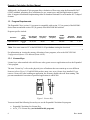
Remote Automation Solutions Expanded Calculation Set Program (For ROC800-Series Remote Operations Controllers) User Manual (QER 06Q018) Form A6203 January 2009 Expanded Calculation Set User Manual Revision Tracking Sheet January 2009 This manual may be revised periodically to incorporate new or updated information. The revision date of each page appears at the bottom of the page opposite the page number. A change in revision date to any page also changes the date of the manual that appears on the front cover. Listed below is the revision date of each page (if applicable): Page All pages Initial release Revision Jan-09 Sep-06 NOTICE “Remote Automation Solutions (“RAS”), division of Emerson Process Management shall not be liable for technical or editorial errors in this manual or omissions from this manual. RAS MAKES NO WARRANTIES, EXPRESSED OR IMPLIED, INCLUDING THE IMPLIED WARRANTIES OF MERCHANTABILITY AND FITNESS FOR A PARTICULAR PURPOSE WITH RESPECT TO THIS MANUAL AND, IN NO EVENT SHALL RAS BE LIABLE FOR ANY INCIDENTAL, PUNITIVE, SPECIAL OR CONSEQUENTIAL DAMAGES INCLUDING, BUT NOT LIMITED TO, LOSS OF PRODUCTION, LOSS OF PROFITS, LOSS OF REVENUE OR USE AND COSTS INCURRED INCLUDING WITHOUT LIMITATION FOR CAPITAL, FUEL AND POWER, AND CLAIMS OF THIRD PARTIES. Bristol, Inc., Bristol Canada, BBI SA de CV and Emerson Process Management Ltd, Remote Automation Solutions division (UK), are wholly owned subsidiaries of Emerson Electric Co. doing business as Remote Automation Solutions (“RAS”), a division of Emerson Process Management. FloBoss, ROCLINK, Bristol, Bristol Babcock, ControlWave, TeleFlow and Helicoid are trademarks of RAS. AMS, PlantWeb and the PlantWeb logo are marks of Emerson Electric Co. The Emerson logo is a trademark and service mark of the Emerson Electric Co. All other trademarks are property of their respective owners. The contents of this publication are presented for informational purposes only. While every effort has been made to ensure informational accuracy, they are not to be construed as warranties or guarantees, express or implied, regarding the products or services described herein or their use or applicability. RAS reserves the right to modify or improve the designs or specifications of such products at any time without notice. All sales are governed by RAS’ terms and conditions which are available upon request. RAS does not assume responsibility for the selection, use or maintenance of any product. Responsibility for proper selection, use and maintenance of any RAS product remains solely with the purchaser and end-user.” © 2006-2009 Remote Automation Solutions, division of Emerson Process Management. All rights reserved. ii Rev. Jan-09 Expanded Calculation Set User Manual Contents Page 1 INTRODUCTION 1.1 1.2 1.3 Scope and Organization.......................................................................................................1 Product Overview.................................................................................................................1 Program Requirements ........................................................................................................2 1.3.1 License Keys............................................................................................................2 2 INSTALLATION 2.1 2.2 3.3 3.4 3.5 Rev. Jan-09 9 Device Information Screen.................................................................................................10 Station Screen....................................................................................................................11 3.2.1 Station – General Tab ............................................................................................12 3.2.2 Station – Gas Quality Tab......................................................................................14 3.2.3 Station – Advanced Tab.........................................................................................16 3.2.4 Station – Alarms Tab .............................................................................................18 Differential Meters Screen..................................................................................................19 3.3.1 Differential Meters – General Tab..........................................................................20 3.3.2 Differential Meters – Inputs Tab.............................................................................22 3.3.3 Differential Meters – Advanced Tab.......................................................................24 3.3.4 Differential Meters – Alarms Tab ...........................................................................26 3.3.5 Differential Meters – Calibration Factors Tab ........................................................27 3.3.6 Differential Meters – GOST Tab ............................................................................28 Linear Meters Screen.........................................................................................................29 3.4.1 Linear Meters – General Tab .................................................................................30 3.4.2 Linear Meters – Inputs Tab ....................................................................................31 3.4.3 Linear Meters – Advanced Tab..............................................................................33 3.4.4 Linear Meters – Alarms Tab...................................................................................35 3.4.5 Linear Meters – Calibration Factors Tab................................................................36 3.4.6 Linear Meters – Mass Meter Press Effect Tab ......................................................37 Saving the Configuration....................................................................................................38 4 REFERENCE MATERIALS 4.1 4.2 4.3 3 Installing the License Key ....................................................................................................3 2.1.1 Verifying the License Key Installation ......................................................................4 Downloading the ExpandedCalc.tar Program......................................................................5 3 CONFIGURATION 3.1 3.2 1 41 Point Type 60: Differential Meter Configuration.................................................................42 Point Type 61: Station Configuration .................................................................................45 Point Type 62: Linear Meter Configuration ........................................................................46 iii Expanded Calculation Set User Manual [This page is intentionally left blank.] , iv Rev. Jan-09 Expanded Calculation Set User Manual 1 INTRODUCTION 1.1 Scope and Organization This document serves as the user manual for the Expanded Calculation Set program (QER 06Q018), which is intended for use in the ROC800-Series Remote Operations Controllers (“ROC800s”). This manual describes how to download, install, and configure the Expanded Calculation Set user program (referred to as the “Expanded Calcs program” or “the program” throughout the rest of this manual). You access and configure this program using ROCLINK™ 800 Configuration Software loaded on an IBMcompatible personal computer running 2000 (with Service Pack 2), XP, or Vista. The sections in this manual provide information in a sequence appropriate for first-time users. Once you become familiar with the procedures and the software, the manual becomes a reference tool. This manual has the following major sections: Section 1 – Introduction Section 2 – Installation Section 3 – Configuration Section 4 – Reference This manual assumes that you are familiar with the ROC800s and their configuration. For more information, refer to the following manuals: ROC809 Remote Operations Controller Instruction Manual (Form A6116). ROC827 Remote Operations Controller Instruction Manual (Form A6175). ROCLINK 800 Configuration Software User Manual (Form A6121). 1.2 Product Overview The Expanded Calculation Set program enables a ROC800 to calculate the density, viscosity, and specific heat ratio of various pure fluids based on the National Institute of Standards and Technology Standard Reference Database 23 (NIST 23). The program then copies these physical property values to the associated meter and station parameters, which enables the calculation of mass, standard volume, and energy flow rates and accumulations. The program supports the following fluids: oxygen, nitrogen, hydrogen, carbon dioxide (liquid), carbon dioxide (vapor), carbon monoxide, helium, argon, steam, and water. Additionally, the program supports the configuration of air and natural gas, which permits the use of a single interface, regardless of the fluid type. The standard firmware calculates air and natural gas properties using the American Gas Association Report No. 8 (AGA8). This program also supplements the flow calculation capabilities of the ROC800 to support calculation of flow through various types of differential and linear meters. Differential meter types supported include flange-tapped orifice, Venturi, Annubar, and V-Cone. Any linear meter that provides either an actual (gross) volume or a mass flow (represented as either a pulse or analog input or retrieved through serial communications) is supported. Rev. Jan-09 1 Expanded Calculation Set User Manual Additionally, the Expanded Calcs program allow calculation of flow rates using the Russian MI-2667 (GOST) standard, permitting flow calculations for gas, steam/water, and fluid applications in metric units. It supports installations implementing either an Annubar Diamond II or an Annubar 485 T-shaped element. 1.3 Program Requirements The Expanded Calcs (version 1.1) program is compatible with version 2.13 (or greater) of the ROC800Series firmware and with version 1.83 (or greater) of the ROCLINK 800 software. Program specifics include: File Name Target Unit/ Version User Defined Point (UDP) Flash Used (in bytes) SRAM Used (in bytes) DRAM Used (in bytes) ROCLINK 800 Version Display Number ExpandedCalc.tar ROC800 2.13 60, 61, 62 84,621 924 290,816 1.83 1, 2, 3 Note: You must connect a PC to the ROC800’s LOI port before starting the download. For information on viewing the memory allocation of user programs, refer to the ROCLINK 800 Configuration Software User Manual (Form A6121). 1.3.1 License Keys License keys, when matched with valid license codes, grant access to applications such as the Expanded Calcs program. The term “license key” refers to the physical piece of hardware that can contain up to seven different licenses (refer to Figure 1). Each ROC800 can have none, one, or two license keys installed. If you remove a license key after enabling an application, the firmware disables the task from running. This prevents unauthorized execution of protected applications in a ROC800. J1 U1 DOC0422A Figure 1. License Key You must install the following license keys to use the Expanded Calculation Set program. 2 Expanded Calculation Set License Key. AGA_3/7/8 License Key (not included in this program). Rev. Jan-09 Expanded Calculation Set User Manual 2 INSTALLATION This section provides instructions for installing the Expanded Calcs program. Read Section 1.3 of this manual for program requirements. 2.1 Installing the License Key If you order the Expanded Calcs program for a new ROC800, your ROC800 is delivered with the license key installed. Go to Section 2.2. If you order the program for an existing ROC800, you must install the license key yourself. Caution Failure to exercise proper electrostatic discharge precautions, such as wearing a grounded wrist strap may reset the processor or damage electronic components, resulting in interrupted operations. When working on units located in a hazardous area (where explosive gases may be present), make sure the area is in a non-hazardous state before performing these procedures. Performing these procedures in a hazardous area could result in personal injury or property damage. To install a license key: 1. Remove power from the ROC800. 2. Remove the wire channel cover. 3. Unscrew the screws from the Central Processing Unit (CPU) faceplate. 4. Remove the CPU faceplate. 5. Place the license key in the appropriate terminal slot (P4 or P6) in the CPU. Incorrect Correct DOC0423A Figure 2. License Key Installation Note: When using a single license key, install it in slot P4. 6. Press the license key into the terminal until it is firmly seated (refer to Figure 2). 7. Replace the CPU faceplate. 8. Replace the screws on the CPU faceplate. 9. Replace the wire channel cover. 10. Restore power to the ROC800. Rev. Jan-09 3 Expanded Calculation Set User Manual 2.1.1 Verifying the License Key Installation After you install the license key, you can verify whether the ROC800 recognizes the key. From the ROCLINK 800 screen, select Utilities > License Key Administrator. The License Key Administrator screen displays: Figure 3. License Key Administrator The Expanded Calc program appears in the Application Name column. (For further information on the License Key Administrator screen, refer to the ROCLINK 800 Configuration Software User Manual, Form A6121). Note: The value in the App Code field on this screen indicates the total number of stream licenses available on this ROC800. After you verify that the license key is correctly installed and recognized, proceed to Section 2.2. 4 Rev. Jan-09 Expanded Calculation Set User Manual 2.2 Downloading the ExpandedCalc.tar Program This section provides instructions for installing the ExpandedCalcs.tar program file into the Flash memory on the ROC800. To download the program using ROCLINK 800 software: 1. Select any empty program number into which to download the program: Figure 4. User Program Administrator 2. Click Browse in the Download User Program File frame. The Select User Program File screen displays (see Figure 5). 3. Select the path and user program file to download from the CD-ROM. (Program files are typically located in the Program Files folder on the CD-ROM.) As Figure 5 shows, the screen lists all valid user program files with the .TAR extension: Rev. Jan-09 5 Expanded Calculation Set User Manual Figure 5. Select User Program File 4. Click Open to select the program file. The User Program Administrator screen displays. As shown in Figure 6, note that the Download User Program File frame identifies the selected program and that the Download & Start button is active: Figure 6. User Program Administrator 5. Click Download & Start to begin loading the selected programs. The following message displays: 6 Rev. Jan-09 Expanded Calculation Set User Manual Figure 7. Confirm Download 6. Click Yes to begin the download. When the download completes the following message displays: Figure 8. ROCLINK 800 Download Confirmation 7. Click OK. The User Program Administrator screen displays (see Figure 9). Note that: The Device User Program Environment frame reflects the use of system memory. The User Programs Installed in Device frame identifies the installed program(s). Figure 9. User Program Administrator Rev. Jan-09 7 Expanded Calculation Set User Manual 8. Click Close. The ROCLINK 800 screen displays and the download is complete. Figure 10. ROCLINK 800 8 Rev. Jan-09 Expanded Calculation Set User Manual 3 CONFIGURATION After you have loaded the Expanded Calcs program on the ROC800, you configure the program using one ROCLINK 800 screen (Device Information) and three program-specific screens (Station, Differential Meters, and Linear Meters): Use the Points tab on the ROCLINK 800 Device Information screen (ROC > Information) to configure the number of active orifice (differential) meters and the number of active linear (turbine, including the Coriolis mass) meters. Use the Station screen to select the calculation standard and specify the fluid being measured or the percentage of various components in the fluid. Use the Differential Meters screen to select the type of meter and to specify meter-specific parameters for supported differential meters (orifice, Venturi, Annubar, or V-Cone). Use the Linear Meters screen to select either a volume or mass input and to specify meterspecific parameters for supported linear meter runs (turbine, PD meter, ultrasonic, or Coriolis). To configure the program (after logging onto ROCLINK 800 and successfully installing the program and license key), proceed through the program screens as shown in this section. You can access all the program-specific screens from the main ROCLINK 800 screen: Figure 11. ROCLINK 800 Rev. Jan-09 9 Expanded Calculation Set User Manual 3.1 Device Information Screen Use this screen to set the active number of meters. To access this screen: 1. Select ROC > Information from the ROCLINK menu bar. The Device Information screen displays. 2. Select the Points tab. Figure 12. Device Information, Points tab 3. Review—and change as necessary—the values in the following fields: Note: Each AGA 3/7/8 license key accommodates a maximum of six meter runs. You can define any combination of active orifice meter runs and active turbine meter runs, as long as the sum of the two does not exceed the maximum of 6 runs. Provided you have a maximum of two AGA 3.7.8 license keys installed, the system can support a total of 12 runs. Field Description Orifice Indicates the number of active orifice (differential) meters. Turbine Indicates the number of active turbine (linear) meters. 4. Click Apply to save your changes. 5. Click OK to close the screen. 6. Proceed to Section 3.2 to configure station values. 10 Rev. Jan-09 Expanded Calculation Set User Manual 3.2 Station Screen Use this screen and its tabs to specify a broad range of station-specific parameters. To access this screen: 1. From the Directory Tree, select User Program > Program #1, ExpandedCalc > Display #1, Station. 2. Double-click #1, Station 1. The Station screen displays, showing the General tab: Figure 13. Station, General tab Note: The Station screen—like the Differential Meters and Linear Meters screens—has a tab format. Sections 3.2.1 through 3.2.4 discuss the requirements for each tab on the Station screen. Rev. Jan-09 11 Expanded Calculation Set User Manual 3.2.1 Station – General Tab Use this tab (which displays when you access the Station screen) to provide general information about the station. Figure 14. Station, General tab 1. Review the values in the following fields: Field Description Station Indicates the current station. Click to display additional stations for this screen. Tag Provides a short description (up to 10 alphanumeric characters) for the selected station. History Segment Indicates the segment in the historical database in which the program stores history points for meters in this station. Contract Hour Indicates the hour at which the system totals values for a single day of production, clears today’s accumulators, and logs data to the Daily History database. 0 represents midnight on a 24-hour clock. Note: Ensure that this value is correct for your organization. Changing this value directly affects the “contract hour” in the history segment configuration. 12 Calculation Standard Indicates the standard the program uses for calculations. The default value is Gas, AGA3-92/AGA7-96/AGA11-2003. Fluid Type Sets the fluid the station handles. Click to display all valid selections. The default value is Natural Gas. Station Values These display-only fields show the current values defined for various station parameters. Rev. Jan-09 Expanded Calculation Set User Manual Field Description Active Alarms This display-only field shows any flow alarms currently active. 2. Click Apply to save any changes you have made to this screen. 3. Proceed to Section 3.2.2 to define gas quality parameters for the station. Rev. Jan-09 13 Expanded Calculation Set User Manual 3.2.2 Station – Gas Quality Tab Use this tab to set up specifics of gas quality for a station. 1. Select the Gas Quality tab on the Station screen: Figure 15. Station, Gas Quality tab 2. Review the values in the following fields: Field Description Gas Component Sets (for each indicated gas) the mole % components present in the natural gas this station is measuring. Note: These selections are valid only if the selected fluid type is natural gas or air. For all other fluids, the program sets the appropriate gas components. Heavy Gas Option Indicates whether the program splits the mole percentage of hexane and heavier hydrocarbons into mole percents of hexane, heptane, octane, nonane, and decane, based on a pre-determined split (displayed on the Advanced tab). Gas Quality Sets the source of the gas quality values. Valid values are Constant (values are manually entered) or Live (values are updated by an online gas chromatograph). Note: If you select Live, the program does not generate either events or periodic and daily history records when the gas quality values change. If you select Constant, the program does generate both events and period and daily history records when the gas quality values change. 14 Rev. Jan-09 Expanded Calculation Set User Manual Field Description Normalization Type Sets how the program adjusts the gas composition if the entered values do not add up to 100 percent. Valid values are Methane Adjust (the program adjusts the mole percentage of methane up or down to force the total mole percentage to 100) or Full Normalization (the program adjusts all components proportionally to their original values to force the total mole percentage to 100). Heating Value Basis Indicates the conditions assumed for the entered heating value. Valid values are Dry (heating value represents the gas without a water component), Wet (heating value represents the gas saturated with water at the flowing pressure and temperature), or As Deliv (heating value represents the gas in the state as delivered to the customer). Heating Value Indicates the heat of combustion of the fluid. 3. Click Apply to save any changes you have made to this screen. 4. Proceed to Section 3.2.3 to define advanced parameters for stations. Rev. Jan-09 15 Expanded Calculation Set User Manual 3.2.3 Station – Advanced Tab Use this tab to set up parameters for stations. 1. Select the Advanced tab on the Station screen: Figure 16. Station, Advanced tab 2. Review the values in the following fields: Field Description Property Calculation Indicates the supercompressibility property calculation associated with this station. Note: Generally the fluid type automatically determines the property calculation as NIST 23. For air, the only valid property calculation is Detailed (AGA8). For natural gas, however, you can select Detailed (AGA8), Gross 1 (AGA8) or Gross 2 (AGA8). Units Sets the engineering units the program uses. US is the default value. Base Conditions Sets values for the pressure, temperature, and density the program uses to calculate the net or corrected volume. For Base Density, if you select Enter, provide a value in lb/ft3 at the specified base pressure and temperature in the associated field. If you select Calculate, the program displays the calculated base density value in the associated field. Atmospheric Pressure Indicates how the program calculates atmospheric pressure. Valid values are Calculate (calculate value from elevation) or Enter (use the value provided). Note: If you select Enter, you must also provide a value in the associated field. Site Data 16 Sets values for the meter site’s elevation (above sea level) and latitude (in degrees of latitude). Rev. Jan-09 Expanded Calculation Set User Manual Field Description Local Gravitational Acceleration Sets whether the program uses an entered value or calculates the local gravitational acceleration. If you select Enter, provide the value in the associated field. If you select Calculate, the program calculates the local gravitational acceleration from the site elevation and latitude (entered on the Advanced tab). Heavy Gas Distribution (C6+) Assigns the mole percentages of the composite heavy gas mole percentage (usually referred to as “hexane+” or “C6+”) the program assigns to hexane, heptane, octane, nonane, and decane. The percentages must add to 100. If the Total % of the distribution among the five heavier components is less than 100, the program increases the values for decane first, then nonane, octane, heptane, and hexane, until the total equals 100%. Similarly, if the Total % is more than 100, the program reduces the values for decane, nonane, octane, heptane, and hexane until the total equals 100%. Note: These adjustments do not display on the screen. 3. Click Apply to save any changes you have made to this screen. 4. Proceed to Section 3.2.4 to define alarms for stations. Rev. Jan-09 17 Expanded Calculation Set User Manual 3.2.4 Station – Alarms Tab Use this tab to set up alarms and spontaneous report-by-exception (SRBX) messages. 1. Select the Alarms tab on the Station screen: Figure 17. Station, Alarms tab 2. Review the values in the following fields: Field Description Alarming Activates or disables the alarm function based on flow value. You can set alarms to trigger on either volume/day or mass/day. High Alarm Sets the value that flow must exceed before the program generates a high alarm. Define units using the Alarming field: MSCF/Day or kM3/Day for Volume/Day or MLb/Day or Tonnes/Day for Mass/Day. Low Alarm Sets the value that flow must fall below before the program generates a low alarm. Define units using the Alarming field: MSCF/Day or kM3/Day for Volume/Day or MLb/Day or Tonnes/Day for Mass/Day Alarm Deadband Sets alarm limits in which the flow must fall within before the program clears an existing alarm. Define units using the Alarming field: MSCF/Day or kM3/Day for Volume/Day or MLb/Day or Tonnes/Day for Mass/Day RBX Sets whether the program generates a spontaneous report-by-exception (SRBX) message when a flow alarm for this meter is set and/or cleared. 3. Click Apply to save any changes you have made to this screen. 4. Proceed to Section 3.3 to define parameters for differential meters. 18 Rev. Jan-09 Expanded Calculation Set User Manual 3.3 Differential Meters Screen Use this screen and its tabs to specify a broad range of meter-specific parameters for supported differential meters (orifice, Venturi, Annubar, or V-Cone). To access this screen: 1. From the Directory Tree, select User Program > Program #1, ExpandedCalc > Display #2, Differential Meters. 2. Double-click #1, Orifice 1. The Differential Meters screen displays, showing the General tab: Figure 18. Differential Meters, General tab Note: The Differential Meters screen—like the Station and Linear Meters screens—has a tab format. Sections 3.3.1 through 3.3.6 discuss the requirements for each tab on the Differential Meters screen. Rev. Jan-09 19 Expanded Calculation Set User Manual 3.3.1 Differential Meters – General Tab Use this tab (which displays when you access the Differential Meters screen) to provide general information about the differential meters. Figure 19. Differential Meters, General tab 1. Review the values in the following fields: Field Description Diff Meter Indicates the current differential meter. Click to display additional differential meters for this screen. Tag Provides a short description (up to 10 alphanumeric characters) for the selected differential meter. Station Indicates the station associated with this differential meter. Click to display all valid selections. Meter Description Provides a user-defined description of up to 30 alphanumeric characters to further identify the selected differential meter. Meter Type Sets the physical type of differential meter installed. Click to display all valid selections. The default value is Flange Tapped Orifice. Note: For Venturi (ASME MFC-3m- 1989) meters, you must define a coefficient of discharge. For generic Annubar meters, you must define the probe width and the flow coefficient. For V-Cone meters, you must define a flow coefficient. Pipe Internal Diameter 20 Defines the internal diameter of the meter pipe. Rev. Jan-09 Expanded Calculation Set User Manual Field Description Diameter Defines the measured diameter of the meter selected in the Meter Type field. If the Meter Type is Flange Tapped Orifice, this value indicates the measured diameter of the orifice. If the Meter Type is Venturi, this value indicates the internal diameter of the throat section of the meter. If the Meter Type is Annubar, this value indicates the width of the Annubar probe. (The program sets probe width for all other types of Annubar meters.) If the Meter Type is V-Cone, this value indicates the internal diameter of the V-Cone meter. Low Flow Cutoff Note: This field’s label changes based on the meter type selected. Sets the minimum value of differential pressure (DP) the program considers as a valid flow. If the DP falls below this value, the program sets all flow values to zero. Flow/Discharge Coefficient Displays the calculated flow or discharge coefficient for flange-tapped orifice meters and defined Annubar meter types. For Venturi, Annubar other, and VCone meters, enter the value of the flow or discharge coefficient provided with the meter calibration sheet supplied with the meter. Active Alarms This display-only field shows any flow alarms currently active. 2. Click Apply to save any changes you have made to this screen. 3. Proceed to Section 3.3.2 to define inputs for differential meters. Rev. Jan-09 21 Expanded Calculation Set User Manual 3.3.2 Differential Meters – Inputs Tab Use this tab to set up values for differential pressure, static pressure, and temperature. 1. Select the Inputs tab on the Differential Meters screen: Figure 20. Differential Meters, Inputs tab 2. Review the values in the following fields: Field Description Differential Pressure Assigns the point type, logical, and parameter (TLP) of the differential pressure value across the meter (or high differential pressure, if you enabled Stacked DP). Click … to display the Select TLP screen and define your TLP selection. Note: If you select Undefined for the I/O Definition, you can enter a value for the differential pressure. Otherwise, the program displays the value for the currently selected input. Static Pressure Assigns the point type, logical, and parameter (TLP) of the pressure of the fluid in the line, either upstream or downstream. (See the descriptions for Pressure Tap selections on the Advanced tab.) Click … to display the Select TLP screen and define your TLP selection. Note: If you select Undefined for the I/O Definition, you can enter a value for the static pressure. Otherwise, the program displays the value for the currently selected input. 22 Rev. Jan-09 Expanded Calculation Set User Manual Field Description Temperature Assigns the point type, logical, and parameter (TLP) for the temperature of the fluid in the line. Click … to display the Select TLP screen and define your TLP selection. Note: If you select Undefined for the I/O Definition, you can enter a value for the temperature. Otherwise, the program displays the value for the currently selected input. Stacked DP Provides an option to allow two differential pressure transmitters for low and high differential pressure ranges. Valid values are Enabled (allow two transmitters) or Disabled (allow only one transmitter). Low DP Input Assigns the point type, logical, and parameter (TLP) of the differential pressure input the program uses in low flow conditions. Click … to display the Select TLP screen and define your TLP selection. Note: This option is valid only if Stacked DP is enabled. Low DP SetPoint Sets the switchover value at which the meter switches from using the high DP input to the low DP input. Note: This option is valid only if Stacked DP is enabled. High DP SetPoint Sets the switchover value at which the meter switches from using the low DP input to the high DP input. Note: This option is valid only if Stacked DP is enabled. 3. Click Apply to save any changes you have made to this screen. 4. Proceed to Section 3.3.3 to define advanced parameters for differential meters. Rev. Jan-09 23 Expanded Calculation Set User Manual 3.3.3 Differential Meters – Advanced Tab Use this tab to set up parameters for differential meters. 1. Select the Advanced tab on the Differential Meters screen: Figure 21. Differential Meters, Advanced tab 2. Review the values in the following fields: 24 Field Description Meter Material Indicates the meter’s construction material. Meter Ref Temp Sets the temperature at which the meter’s dimension (orifice diameter, throat diameter, probe width, or V-Cone diameter) was measured. Pipe Material Indicates the meter tube’s construction material. Pipe Ref Temp Sets the temperature at which the pipe’s internal diameter was measured. Pressure Tap Identifies the location of the static pressure tap and the type of static input. Select Upstream or Downstream to indicate the physical location of the pressure tap relative to the meter. Select Gauge if the static pressure transmitter produces a pressure relative to atmospheric pressure, or select Absolute if the transmitter produces a pressure relative to a vacuum. Rev. Jan-09 Expanded Calculation Set User Manual Field Description Viscosity Sets whether the program uses an entered value for the fluid’s viscosity, uses a default viscosity for the selected fluid, or calculates (at flowing temperature and pressure) a viscosity value for the selected fluid. If you select Enter, provide a value in centipoise in the associated field. Note: Calculate is an option only if you have selected either Natural Gas or Air as a Fluid Type on the Station screen’s General tab. Also, a program default is to display viscosity in cP, unless you have selected Natural Gas as the Fluid Type and US as the Units. Specific Heat Ratio Sets whether the program uses an entered value for the fluid’s specific heat ratio, uses a default specific heat ratio for the selected fluid, or calculates (at flowing temperature and pressure) a specific heat ratio value for the selected fluid. If you select Enter, provide a value in the associated field. Note: If you select either Calculate or Use Default, the program displays the specific heat ratio value in the associated field. Calculate is an option only if you have selected either Natural Gas or Air as a Fluid Type on the Station screen’s General tab. Flowing Density Sets values for density at the flowing pressure and temperature. If you select Enter, provide a value in the associated field. If you select Calculate, the program displays the flowing density value in the associated field. Note: Enter is an option only if you have selected either Natural Gas or Air as a Fluid Type on the Station screen’s General tab. 3. Click Apply to save any changes you have made to this screen. 4. Proceed to Section 3.3.4 to define alarms for differential meters. Rev. Jan-09 25 Expanded Calculation Set User Manual 3.3.4 Differential Meters – Alarms Tab Use this tab to set up alarms and spontaneous report-by-exception (SRBX) messages. 1. Select the Alarms tab on the Differential Meters screen: Figure 22. Differential Meters, Alarms tab 2. Review the values in the following fields: Field Description Alarming Activates or disables the alarm function based on flow value. You can set alarms to trigger on volume/day, mass/day, volume/hour, or mass/hour. High Alarm Sets the value that flow must exceed before the program generates a high alarm. Define units using the Alarming field: MSCF/Day or kM3/Day for Volume/Day; MLb/Day or Tonnes/Day for Mass/Day; SCF/Hr or m3/Hr for Volume/Hour, or Lb/Hr or Kg/Hr for Mass/Hour. Low Alarm Sets the value that flow must fall below before the program generates a low alarm. Define units using the Alarming field: MSCF/Day or kM3/Day for Volume/Day; MLb/Day or Tonnes/Day for Mass/Day; SCF/Hr or m3/Hr for Volume/Hour, or Lb/Hr or Kg/Hr for Mass/Hour. Alarm Deadband Sets alarm limits in which the flow must fall within before the program clears an existing alarm. Define units using the Alarming field: MSCF/Day or kM3/Day for Volume/Day; MLb/Day or Tonnes/Day for Mass/Day; SCF/Hr or m3/Hr for Volume/Hour, or Lb/Hr or Kg/Hr for Mass/Hour. SRBX Sets whether the program generates a spontaneous report-by-exception (SRBX) message when a flow alarm for this meter is set and/or cleared. 3. Click Apply to save any changes you have made to this screen. 4. Proceed to Section 3.3.5 to define calibration factors for differential meters. 26 Rev. Jan-09 Expanded Calculation Set User Manual 3.3.5 Differential Meters – Calibration Factors Tab Use this tab to set up calibration parameters. 1. Select the Calibration Factors tab on the Differential Meters screen. Figure 23. Differential Meters, Calibration Factors tab 2. Review the values in the following fields: Field Description Deadweight Gravitational Correction Sets the option the program uses to correct the flow rate for calibration errors resulting from a deadweight test performed at a location with a gravitational acceleration that differs from that during calibration of the deadweight set. Select a correction independently for each type of input, since the program applies the correction twice if the deadweight test set is used to calibrate both the differential pressure and static pressure. Enter a value for the gravitational acceleration at the location where the deadweight set was calibrated. User Correction Factor Sets a flow factor value the system multiplies by the flow equation to correct for calibration errors from other calibration equipment. You can also use this factor for special user applications. 3. Click Apply to save any changes you have made to this screen. 4. Proceed to Section 3.3.6 to define GOST-related parameters for differential meters. Rev. Jan-09 27 Expanded Calculation Set User Manual 3.3.6 Differential Meters – GOST Tab Use this tab to set up GOST-related flow calculations for differential meters. 1. Select the GOST tab on the Differential Meters screen. Figure 24. Differential Meters, GOST tab 2. Review the values in the following fields: Field Description GOST Selects the GOST flow calculation for the meter run. Note: If you select this check box, the program automatically resets the Units to Metric, Fluid Type to Natural Gas, and Meter Type to Annubar Type 1 (if you have not already selected a valid Annubar option as a Meter Type). Pipe Coefficient A, B, C Sets (for each pipe choice) the coefficient value required for corrections to pipe diameter, in accordance with the GOST 8.563.1 standard. Probe Coefficient A, B, C Sets (for each probe choice) the coefficient value required for corrections to probe diameter, in accordance with the GOST 8.563.1 standard. Pipe Diameter @ Temp This read-only field shows the corrected pipe diameter for temperature at flowing conditions, calculated according to the GOST 8.563.1 standard. Probe Diameter @ Temp This read-only field shows the corrected Annubar probe (orifice) diameter for temperature at flowing conditions, calculated according to the GOST 8.563.1 standard. 3. Click Apply to save any changes you have made to this screen. 4. Proceed to Section 3.4 to define parameters for linear meters. 28 Rev. Jan-09 Expanded Calculation Set User Manual 3.4 Linear Meters Screen Use this screen and its tabs to specify a broad range of meter-specific parameters for supported linear meters (turbine, positive displacement, ultrasonic, and Coriolis). To access this screen: 1. From the Directory Tree, select User Program > Program #1, ExpandedCalc > Display #3, Linear Meters. 2. Double-click #1, Turbine 1. The Linear Meters screen displays, showing the General tab: Figure 25. Linear Meters, General tab Note: The Linear Meters screen—like the Station and Differential Meters screens—has a tab format. Sections 3.4.1 through 3.4.6 discuss the requirements for each tab on the Linear Meters screen. Rev. Jan-09 29 Expanded Calculation Set User Manual 3.4.1 Linear Meters – General Tab Use this tab (which displays when you access the Linear Meters screen) to provide general information about linear meters. Figure 26. Linear Meters, General tab 1. Review the values in the following fields: Field Description Linear Meter Indicates the currently displayed linear meter. Click to display additional linear meters for this screen. Tag Provides a short description (up to 10 alphanumeric characters) for the selected linear meter. Station Indicates the station associated with this linear meter. Click to display all valid selections. Meter Description Provides a user-defined description of up to 30 alphanumeric characters to further identify the selected linear meter. Meter Type Sets the physical type of linear meter installed. Valid values are Volume or Mass. The default value is Volume. Note: This selection changes the field labels on the Inputs tab. If you select Volume, the first field on the Inputs tab is Uncorrected Value. If you select Mass, the first field on the Inputs tab is Mass. Active Alarms This display-only field shows any flow alarms currently active. 2. Click Apply to save any changes you have made to this screen. 3. Proceed to Section 3.4.2 to define inputs for the linear meters. 30 Rev. Jan-09 Expanded Calculation Set User Manual 3.4.2 Linear Meters – Inputs Tab Use this tab to set up uncorrected volume, static pressure, and temperature information for the linear meters. 1. Select the Inputs tab on the Linear Meters screen: Figure 27. Linear Meters, Inputs Tab 2. Review the values in the following fields: Field Description Uncorrected Volume Assigns the point type, logical, and parameter (TLP) of the uncorrected or gross volume (volume at flowing pressure and temperature) through the meter. Click … to display the Select TLP screen and define your TLP selection. If you select Undefined for the uncorrected volume input, you can enter a value for the uncorrected volume flow rate. Otherwise, the program displays the value for the currently selected input. Note: This field displays only if you selected Volume as the Meter Type on the General Tab. Mass Assigns the point type, logical, and parameter (TLP) of the value of the mass flow through the meter. Click … to display the Select TLP screen and define your TLP selection. If you select Undefined for the mass input, you can enter a value for the mass flow rate. Otherwise, the program displays the value for the currently selected input. Note: This field displays only if you selected Mass as the Meter Type on the General Tab. Rev. Jan-09 31 Expanded Calculation Set User Manual Field Description Static Pressure Assigns the point type, logical, and parameter (TLP) of the value of the pressure of the fluid in the line. Click … to display the Select TLP screen and define your TLP selection. Note: If you select Undefined for the static pressure input, you can enter a value for the static pressure. Otherwise, the program displays the value for the currently selected input. Temperature Assigns the point type, logical, and parameter (TLP) for the temperature of the fluid in the line. Click … to display the Select TLP screen and define your TLP selection. Note: If you select Undefined for the temperature input, you can enter a value for the temperature. Otherwise, the program displays the value for the currently selected input. 3. Click Apply to save any changes you have made to this screen. 4. Proceed to Section 3.4.3 to define advanced parameters for the linear meters. 32 Rev. Jan-09 Expanded Calculation Set User Manual 3.4.3 Linear Meters – Advanced Tab Use this tab to set up advanced parameters for linear meters. 1. Select the Advanced tab on the Linear Meters screen. Figure 28. Linear Meters, Advanced tab 2. Review the values in the following fields: Field Description Static Pressure Units Indicates the type of static pressure unit. Valid values are Gauge (the static pressure transmitter produces a pressure relative to atmospheric pressure) or Absolute (transmitter produces a pressure relative to a vacuum). Static K Factor Sets the number of pulses represented either as pulses/ft3 or pulses/m3 (for volume) or pulses/Lb or pulses/Kg (for mass). No Flow Time Indicates, in seconds, the amount of time the program waits without receiving a pulse to be considered in a “no flow” condition. Low Flow Cutoff Sets the minimum value of the uncorrected volume or mass input the program considers to be a valid flow. Note: The program applies this value only when the uncorrected volume or mass input is not a pulse input point type. The program counts all pulses and considered them as valid flow. Rev. Jan-09 33 Expanded Calculation Set User Manual Field Description Calculated Speed of Sound Sets whether the program calculates the speed of sound through the fluid. The speed of sound does not affect the flow calculation, but you may compare that value against the measured speed of sound from an ultrasonic meter for diagnostic purposes. Valid values are Disabled (no calculation occurs) or Enabled (calculate speed of sound in accordance with AGA 10). Note: If a serial connection to an ultrasonic meter is available and you select Enabled, the program updates the Calculated field automatically. Measured Speed of Sound Sets the speed of sound as measured by the ultrasonic meter. Variable K Factors Sets whether the program accepts multiple frequency and K factor pairs and then calculates a K factor by interpolating between the entered points. Valid values are Disabled (no calculation occurs) or Enabled (enter up to 12 Frequency/K Factor pairs). Note: If a serial connection to an ultrasonic meter is available, you can map this parameter to a Modbus register for automatic updates. 3. Click Apply to save any changes you have made to this screen. 4. Proceed to Section 3.4.4 to define alarms for the linear meters. 34 Rev. Jan-09 Expanded Calculation Set User Manual 3.4.4 Linear Meters – Alarms Tab Use this tab to set up alarms and spontaneous report-by-exception (SRBX) messages. 1. Select the Alarms tab on the Linear Meters screen. Figure 29. Linear Meters, Alarms tab 2. Review the values in the following fields: Field Description Alarming Activates or disables the alarm function based on flow value. You can set alarms to trigger on volume/day, mass/day, volume/hour, or mass/hour. High Alarm Sets the value that flow must exceed before the program generates a high alarm. Define units using the Alarming field: MSCF/Day or kM3/Day for Volume/Day; MLb/Day or Tonnes/Day for Mass/Day; SCF/Hr or m3/Hr for Volume/Hour, or Lb/Hr or Kg/Hr for Mass/Hour. Low Alarm Sets the value that flow must fall below before the program generates a low alarm. Define units using the Alarming field: MSCF/Day or kM3/Day for Volume/Day; MLb/Day or Tonnes/Day for Mass/Day; SCF/Hr or m3/Hr for Volume/Hour, or Lb/Hr or Kg/Hr for Mass/Hour. Alarm Deadband Sets alarm limits in which the flow must fall within before the program clears an existing alarm. Define units using the Alarming field: MSCF/Day or kM3/Day for Volume/Day; MLb/Day or Tonnes/Day for Mass/Day; SCF/Hr or m3/Hr for Volume/Hour, or Lb/Hr or Kg/Hr for Mass/Hour. SRBX Sets whether the program generates a spontaneous report-by-exception (SRBX) message when a flow alarm for this meter is set and/or cleared. 3. Click Apply to save any changes you have made to this screen. 4. Proceed to Section 3.4.5 to define calibration factors for the linear meters. Rev. Jan-09 35 Expanded Calculation Set User Manual 3.4.5 Linear Meters – Calibration Factors Tab Use this tab to set up calibration factors for linear meters. 1. Select the Calibration Factors tab on the Linear Meters screen. Figure 30. Linear Meters, Calibration Factors tab 2. Review the values in the following fields: Field Description Deadweight Gravitational Correction Sets the option the program uses to correct the flow rate for calibration errors resulting from a deadweight test to calibrate static pressure performed at a location with a gravitational acceleration that differs from that during calibration of the deadweight set. Enter a value for the gravitational acceleration at the location where the deadweight set was calibrated. User Correction Factor Sets a flow factor value the system multiplies by the flow equation to correct for calibration errors from other calibration equipment. You can also use this factor for special user applications. 3. Click Apply to save any changes you have made to this screen. 4. Proceed to Section 3.4.6 to define mass meter pressure effect parameters for the linear meters. 36 Rev. Jan-09 Expanded Calculation Set User Manual 3.4.6 Linear Meters – Mass Meter Press Effect Tab Use this tab to set up options for mass meter pressure effects for linear meters. Note: If you select Volume as the Meter Type on the Linear Meters screen’s General tab, this tab is unavailable for entry. 1. Select the Mass Meter Press Effect tab on the Linear Meters screen. Figure 31. Linear Meters, Mass Meter Press Effect tab 2. Review the values in the following fields: Field Description Mass Pressure Compensation Activates the option the program uses to compensate the raw mass flow reading from a Coriolis meter for pressure effect on the meter. The meter was initially calibrated at a specific line pressure. Changes in pressure affect the stiffness of the metering tube. Valid values are Enabled (you provide a pressure effect coefficient in %/PSI for the program to use) or Disabled (no compensation calculation occurs. Note: This value comes from the meter calibration sheet provided with your Coriolis mass meter. Calibration Pressure Indicates the calibration pressure of the meter in PSIG. This field is required if you enable pressure compensation. Note: This value comes from the meter calibration sheet provided with your Coriolis mass meter. 3. Click Apply to save any changes you have made to this screen. 4. Proceed to Section 3.5 to save the configuration. Rev. Jan-09 37 Expanded Calculation Set User Manual 3.5 Saving the Configuration Whenever you modify or change the configuration, it is a good practice to save the final configuration to memory. To save the configuration: 1. Select ROC > Flags. The Flags screen displays: Figure 32. Flags screen 2. Click Save Configuration. A verification message displays: Figure 33. Perform screen 38 Rev. Jan-09 Expanded Calculation Set User Manual 3. Click Yes. A confirmation message displays: Figure 34. Flags screen 4. Click OK to begin the save process. The Status field on the Flags screen displays In Progress. When the process ends, the Status field on the Flags screen displays Completed. 5. Click Update on the Flags screen. This completes the process of saving your new configuration. Note: For archive purposes, you should also save this configuration to your PC’s hard drive or removable media (such as a diskette or a flash drive) using the File > Save Configuration option on the ROCLINK 800 menu bar. Rev. Jan-09 39 Expanded Calculation Set User Manual [This page is intentionally left blank.] 40 Rev. Jan-09 Expanded Calculation Set User Manual 4 REFERENCE MATERIALS This section provides tables of information on the user-defined point types the Expanded Calculation program uses: 60 Differential Meter Configuration. 61 Station Configuration. 62 Linear Meter Configuration. Rev. Jan-09 41 Expanded Calculation Set User Manual 4.1 Point Type 60: Differential Meter Configuration Point type 60 is associated with differential (orifice) meter types. The program maintains one logical point for each active differential meter, and saves point type 60 information to internal configuration memory. Parm # Name Access Program or User Update Data Type Length Range Default Version “Orifice X” where X is the meter number 1.00 0 Tag ID R/O System STRING 10 0x20 -> 0x7E for each ASCII Character 1 Viscosity Option R/W User UINT8 1 0→2 1 1.00 2 Specific Heat Option R/W User UINT8 1 0→2 1 1.00 3 Flowing Density Option R/W User UINT8 1 0→1 1 1.00 42 Description of functionality and meaning of values Identifies the specific differential meter run. This parameter is copied to the associated orifice meter point (113, x, 0). Selection to determine the viscosity of the fluid. 0 = User Entered, 1 = Use default value for fluid selected, 2 = Calculate from fluid type, pressure, and temperature. Selection to determine the specific heat ratio. 0 = User Entered, 1 = Use default value for the fluid selected, 2 = Calculate from fluid type, pressure, and temperature. Selection to determine the density of the fluid at flowing conditions. 0 = User Entered, 1 = Calculated. Rev. Jan-09 Expanded Calculation Set User Manual Parm # Name Access Program or User Update Data Type Length Range Default Version 4 Differential Meter Type R/W User UINT8 1 0, 6, 10 → 25 0 1.00 5 GOST option R/W User UINT8 1 0→1 0 1.00 6 Pipe Coeff A R/W User Float 4 0 1.00 7 Pipe Coeff B R/W User Float 4 0 1.00 8 Pipe Coeff C R/W User Float 4 0 1.00 Rev. Jan-09 Any valid IEEE 754 float Any valid IEEE 754 float Any valid IEEE 754 float Description of functionality and meaning of values Selection for the type of differential meter. 0 = Flange Orifice; 6 = Venturi, 10 = Annubar 485 Type 1, 11 = Annubar 485 Type 2; 12 = Annubar 485 Type 3; 13 = Annubar Diamond Type 10+; 14 = Annubar Diamond Type 15/16+; 15 = Annubar Diamond Type 25/26+; 16 = Annubar Diamond Type 35/36+; 17 = Annubar Diamond Type 45/46+; 18 = Annubar Diamond Type 10-; 19 = Annubar Diamond Type 15/16-; 20 = Annubar Diamond Type 25/26-; 21 = Annubar Diamond Type 35/36-; 22 = Annubar Diamond Type 45/46-; 23 = Annubar Streamline Type 43/44; 24 = Annubar Other (Enter d and K); 25 = V-cone Indicates the GOST calculations to be used with this meter (as opposed to AGA): 0 = Inactive 1 = Active Provides GOST Pipe Coefficient A Provides GOST Pipe Coefficient B Provides GOST Pipe Coefficient C 43 Expanded Calculation Set User Manual Parm # Name Access Program or User Update Data Type Length 9 Probe Coeff A R/W User Float 4 10 Probe Coeff B R/W User Float 4 11 Probe Coeff C R/W User Float 4 12 Pipe @ Temp R/O Program Float 4 13 Probe @ Temp R/O Program Float 4 14 Units R/W User UINT8 1 15 Station Number R/W User UINT8 16 Viscosity R/W Both Float 44 Range Default Version 0 1.00 0 1.00 0 1.00 0 1.00 0 1.00 0→1 0 1.00 1 0 → 11 0 1.00 4 >0 6.9x10⁻⁶ 1.00 Any valid IEEE 754 float Any valid IEEE 754 float Any valid IEEE 754 float Any valid IEEE 754 float Any valid IEEE 754 float Description of functionality and meaning of values Provides GOST Probe Coefficient A Provides GOST Probe Coefficient A Provides GOST Probe Coefficient A Indicates GOST-calculated pipe diameter in millimeters. Indicates GOST-calculated probe diameter in millimeters. Indicates what engineering units the process variables, inputs, and calculation should be. This parameter is copied to the associated station point (112, x, 4). 0 = English Units; 1 = Metric Units. Associates this meter with a particular station. Indicates the viscosity of the fluid. Rev. Jan-09 Expanded Calculation Set User Manual 4.2 Point Type 61: Station Configuration Point type 61 is the point associated with station configuration information. The program maintains one logical point for each active station and saves point type 61 information to internal configuration memory. Parm # 0 Name Tag ID Access R/O Program or User Update System Data Type STRING Length Range Default Version Description of functionality and meaning of values 10 0x20 -> 0x7E for each ASCII Character “Station X” where X is the meter number 1.00 Identifies a specific station. The program copies this tag to the associated station (112, x, 0). 1 Fluid Type R/W User UINT8 1 0 → 11 0 1.00 2 Base Density Option R/W User UINT8 1 0→1 1 1.00 3 Number of GOST Meters R/W Program UINT8 1 0 → 12 0 1.00 Rev. Jan-09 Selection for the type of fluid being measured with this station. 0 = Natural Gas, 1 = Oxygen, 2 = Nitrogen, 3 = Hydrogen, 4 = Helium, 5 = Carbon Monoxide, 6 = Carbon Dioxide Liquid, 7 = Carbon Dioxide Gas, 8 = Steam, 9 = Water, 10 = Argon, 11 = Air. Selection to determine the density of fluid at base conditions. 0 = User entered 1 = System calculated Indicates the number of GOST differential meters associated with this station. 45 Expanded Calculation Set User Manual 4.3 Point Type 62: Linear Meter Configuration Point type 62 contains configuration information for linear (turbine) meter types. The program maintains one logical point for each active linear meter and saves point type 62 information to internal configuration memory. Parm # Name Access Program or User Update Data Type Length Range Default “Orifice X” where X is the meter number 1.00 0 1.00 0 Tag ID R/O System STRING 10 0x20 -> 0x7E for each ASCII Character 1 Units R/W User UINT8 1 0→1 46 Version Description of functionality and meaning of values Identification name for specific Linear Meter Run. The program copies the tag from the associated linear meter run to the linear tag. Indicates the engineering units the process variables, inputs, and calculations use. The program copies this parameter to the associated station point. (112, x, 4) 0 = English (Imperial) units 1 = Metric units. Rev. Jan-09 Expanded Calculation Set User Manual [This page is intentionally left blank.] 47 Rev. Jan-09 Expanded Calculation Set User Manual If you have comments or questions regarding this manual, please direct them to your local sales representative or contact: Emerson Process Management Remote Automation Solutions Marshalltown, Iowa 50158 USA Houston, TX 77065 USA Pickering, North Yorkshire UK Y018 7JA Website: www.EmersonProcess.com/Remote