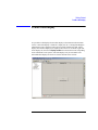
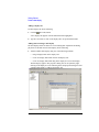
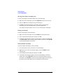
1
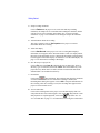
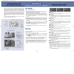
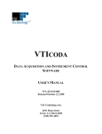
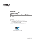
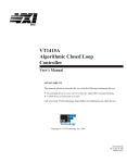
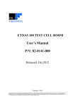
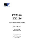
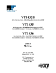
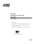
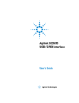
Getting Started with
DAC Express
Part Number 82-0096-000
Printed in U.S.A
Released: October 27, 2008
VXI Technology, Inc., 2008. All rights reserved.
2031 Main Street, CA 92614-6509 U.S.A.
Notices
The information contained in the manual is subject to change without notice.
VXI Technology, Inc. makes no warranty of any kind with regard to this manual,
including, but not limited to, the implied warranties of merchantability and fitness
for a particular purpose. VXI Technology shall not be liable for errors contained
herein or direct, indirect, special, incidental, or consequential damages in
connection with the furnishing, performance, or use of the material.
Trademarks
DAC Express™ is a trademark of VXI Technology, Inc.
Microsoft®, Windows®, MS Windows®, and Windows NT® are U.S. registered
trademarks of Microsoft Corp.
ii
U.S. Government Restricted Rights
The Software and Documentation have been developed entirely at private expense.
They are delivered and licensed as "commercial computer software" as defined in
DFARS 252.227- 7013 (Oct 1988), DFARS 252.211-7015 (May 1991) or DFARS
252.227-7014 (Jun 1995), as a "commercial item" as defined in FAR 2.101(a), or as
"Restricted computer software" as defined in FAR 52.227-19 (Jun 1987)(or any
equivalent agency regulation or contract clause), whichever is applicable. You have
only those rights provided for such Software and Documentation by the applicable
FAR or DFARS clause or the VXI Technology, Inc. standard software agreement for
the product involved.
© Copyright VXI Technology, Inc. 2008.
This document contains proprietary information which is protected by copyright.
VXI Technology, Inc. grants all valid DAC Express license holders permission to
reproduce this copyrighted document for internal use provided it is reproduced
unmodified, in its entirety, including this copyright notice.
iii
DAC Express at a Glance
DAC Express provides a graphical user interface that makes seting up a
multi-channel analog measurement easy, saving time-domain data to disk for future
processing. To assure the acquired data is valid, acquisition can be monitored in real
time.
When DAC Express begins, it automatically finds all supported instruments,
provided each instrument is properly configured. The following shows
DAC Express and identifies its main areas:
Title Bar
Menu Bar
Project View
Document
Window
(displaying the
Channel editor)
Status Bar
•
Title Bar⎯displays the name of the current project. If the project has not been
saved, displays Untitled.
•
Menu Bar⎯provides dropdown menus in the standard Windows® style. The
menus displayed change with the selection in the project view.
•
•
•
•
iv
Toolbar⎯provides toolbar buttons as shortcuts to many menu functions. Each
button can be identified by its tool tip, which appears when the mouse pointer is
held over the button.
Project View⎯provides a hierarchical “tree view” of the DAC Express user
interfaces and allows the currently displayed user interface to be selected.
Document Window⎯displays the DAC Express setup editors, data recorder,
and any recordings or related documents in the project. The selection in the
project view determines the display in this window.
Status Bar⎯displays messages about the current task or process.
The following describes the user interfaces available in the project view:
•
Setup⎯displays an information screen which shows how to access the
following setup editors:
•
•
•
•
•
•
Channels⎯allows the configuration for each channel in the system to be
edited. The tabs at the bottom of the Channels editor allow for switching
between the various instruments and Signal-Conditioning Plug-ons (SCPs)
in the system. The Channels editor contains a row for each channel in the
system and columns that contain identification and configuration
information for each channel.
Timebase⎯provides a way to specify when recording starts and stops. In
addition, it allows independent measurement rates to be set for different
types of instruments.
Test Properties⎯provides a place for user information to be entered about
the recording. Entering information is optional.
Data Recorder⎯allows recording to be enabled or stopped. Actual recording
starts after the conditions set in the Timebase editor have been met. Displays can
be added to monitor the data acquisition in real time.
Data Viewer⎯displays an information screen that describes how to view
previously recorded data. If data has been recorded and saved in the current
project, its recording name is listed below Data Viewer and the setup editors for
the recording are listed below the recording name. Selecting a recording name
allows the data displays to be viewed that were in place when the data was
recorded, add displays, and playback the data. In addition, it is possible to select
a region of the data file to export.
Related Documents⎯displays an information screen that describes how to add
various documents to the project. If documents have been added to the current
project, they are listed below Related Documents.
v
vi
Table of Contents
1
Installing DAC Express
To configure an EX2500A interface 1-8
To configure an IEEE-1394 interface 1-9
To configure an NI VXI-MXI-2 interface 1-11
To configure a GPIB interface 1-12
To reconfigure a PCI interface 1-14
2
Getting Started
To setup channels 2-4
To setup recording conditions 2-8
To add a data display 2-12
To view recorded data 2-16
Need Assistance?
VXI Technology Support Resources
vii
viii
1
1
Installing DAC Express
This chapter provides instructions for installing DAC Express, including
instructions for installing VISA and configuring the interface.
Installing DAC Express
To install DAC Express, do the following:
1. Check that the computer system meets the minimum requirements.
See “Minimum System Requirements” on page 1-4, “Supported Hardware” on
page 1-5, and “Hardware Considerations” on page 1-6.
2. Install the VXI hardware.
See the Getting Started with VXI manual and the documentation that came with
the hardware.
If a preconfigured DAC Express data acquisition system was purchased or the
hardware is already installed, skip this step.
3. Install VISA and configure the interface using one of the following procedures:
Note
•
For an EX2500A interface, see “To configure an EX2500A interface” on
page 1-8.
•
For an IEEE-1394 interface, see “To configure an IEEE-1394 interface” on
page 1-9.
•
For an NI VXI-MXI-2 interface, see “To configure an NI VXI-MXI-2
interface” on page 1-11.
•
For a GPIB interface, see “To configure a GPIB interface” on page 1-12.
This step can be skipped if DAC Express is to be used with only simulated
instruments.
If VISA is already installed and the interface is already configured, verify that
the required version of VISA is installed. For LXI instruments, the EX2500A, or
an IEEE-1394 interface, Ag VISA version 14.2 or later must be installed. For
NI-VXI-MXI-2 interface, NI-VXI/VISA version 2.0 or later must be installed.
1-2
Installing DAC Express
4. Install DAC Express.
Insert the “DAC Express” CD into the PC and wait for the Setup program to
auto-start, then follow the instructions on the screen.
If MATLAB is installed and was ran, the Standard Data Format Toolbox for
MATLAB in the Select Options dialog box can be selected. Although it may be
possible to install the toolbox with a lower version of MATLAB, version 5.3 or
higher must be installed to use the toolbox.
5. Start DAC Express.
From the Windows Start menu, select Programs, then select DAC Express
followed by DAC Express.
6. Verify that DAC Express found the supported instruments.
During startup, DAC Express searches for supported instruments then displays
the instruments it found in the Channels editor. The tabs at the bottom of the
Channels editor show the instruments that were found. The ID column shows the
instrument’s slot and channel numbers. Alternately, click the
(Instrument
Settings) button to see which instruments were found in each slot.
If DAC Express found all the supported instruments go to Chapter 2, “Getting
Started,” to learn the basics.
If DAC Express did not find all the supported instruments, use one of the
following to resolve the instrument communication problems:
•
For an EX2500A, use the VISA Assistant program and the IO Libraries
Suite Getting Started manual. If an EX10xxA or EX1629 is not found, the
LAN connections and configuration settings should be checked in VISA
Assistant as well.
•
For an IEEE-1394 or GPIB interface, use the VISA Assistant program and
the IO Libraries Suite Getting Started manual.
•
For an NI VXI-MXI-2 interface, use the Measurement & Automation
Explorer program and the documentation provided with the NI VXI/VISA
software.
1-3
Installing DAC Express
Minimum System Requirements
•
Windows 2000 or Windows XP
•
600 MHz Pentium III processor
•
128 MB RAM (512 MB RAM recommended)
•
40 MB available space on hard drive plus space for data storage (approximately
4 bytes/sample to record or export VT1413C data and 2 bytes/sample to export
VT1432A/33B data)
•
CD-ROM drive for installation
•
One of the following interfaces:
•
•
VXI Technology, Inc. EX2500A LXI-VXI Slot 0 Interface
•
Agilent E8491A/B IEEE-1394 (FireWire) VXI module and an IEEE-1394
interface. The IEEE-1394 interface is not supported for Windows 98.
•
National Instruments VXI-MXI-2 module and PCI card
•
Agilent E1406 GPIB Command Module and GPIB card (This interface only
supports VT1413/15/19/22 modules)
Display: 15 inch, 800 X 600 resolution
Recommended System Requirements
•
Windows 2000 or Windows XP
•
1 GHz Pentium processor or faster
•
512 MB RAM or more
•
40 MB available space on hard drive plus space for data storage (approximately
4 bytes/sample to record or export VT1413C data and 2 bytes/sample to export
VT1432A/33B data)
•
CD-ROM drive for installation
•
VXI Technology, Inc. EX2500A LXI-VXI Slot 0 Interface
•
Display: 17 inch or larger, 1024 X 768 resolution or higher
1- 4
Installing DAC Express
Supported Hardware
•
VT1413C 64-Channel Scanning A/D
•
•
VT1415A Closed Loop Controller and VT1419A Multifunction plus module
•
•
•
•
All VT1501A through VT1518A, VT1531A through VT1534A, and
VT1536A through VT1539A Signal Conditioning Plug-ons
VT1432A/B 16-Channel 51.2 kSamples/s / 102.4 kSa/s Digitizer plus DSP
(local bus option UGV is required for VT2216A recording)*
•
All breakout boxes supported by VT1432A
•
Options 1D4 (source), AYF (tachometer), 1DD (delete 12 channels), and
1DE (delete 8 channels)
VT1433A/B 8-Channel 196 kSamples/s Digitizer plus DSP (local bus option
UGV is required for VT2216A recording)*
•
All breakout boxes supported by VT1433A/B
•
Options 1D4 (source), AYF (tachometer), and 1DL (delete 4 channels)
VT1434A 4-Channel 65 kSamples/s Arbitrary Source*
•
•
VT1501A through VT1518A, VT1531A through VT1534A, and VT1536A
through VT1538 Signal Conditioning Plug-ons
VT1422A Remote Channel DAC and VT1529A/B Remote Strain Conditioning
Unit
•
•
VT1501A through VT1518A Signal Conditioning Plug-ons
Options 1D4 (source) and 1DM (delete 2 channels)
VT1435 & VT1436 8-Channel / 16-Channel 102.4 kSamples/s Digitizer plus
DSP (local bus option UGV is required for VT2216A recording)*
•
Options 1D4 (source) and AYF (tachometer)
•
VT2216A VXI SCSI I/F and HP/Agilent E1562D/E/F VXI Data Disk
•
EX1048 LXI 48-Channel Precision Thermocouple Instrument
•
EX10xxA LXI 48-Channel Precision Thermocouple/Voltage Instrument
•
EX1629 48-Channel Strain Gauge Instrument
* VT1432-36 Not Supported with GPIB Interface: If you are using the E1406 GPIB Command Module and GPIB
interface, the VT1432, VT1433, VT1434, VT1435, and VT1436 VXI modules are NOT supported. These modules are
supported ONLY with the EX2500A, E8491A/B (IEEE-1394), or NI VXI-MXI-2 (MXIbus) interface. Only the
VT1413/15/19 modules are supported with the EX2500A or GPIB interface.
1-5
Installing DAC Express
Hardware Considerations
•
Only a single VXI mainframe is supported. DAC Express doesn’t support
multiple mainframes daisy-chained together.
•
When more than one EX1629 is used simultaneously, they must be daisychained using LXI bus cables. Any unused LXI connectors must be properly
terminated. DAC Express currently does not support the star trigger
configuration. Please see the EX1629 User's Manual for more information.
•
DAC Express systems with a VT1432B/33B/35/36 Digitizer may also have a
VT2216A VXI Data Disk. Although DAC Express only supports one VT2216A,
a VT2216A VXI Data Disk can be installed to increase throughput storage
capacity.
•
All VT1432B/33B/35/36 Digitizer modules and VT2216A Data Disk modules
use the local bus and must be placed next to each other in the mainframe with
the VT2216A in the furthest right-hand slot.
•
The VXI-MXI-2 module uses the local bus and must be physically separated by
at least one slot from VT1432B/33B/35/36 Digitizer modules, VT2216A Data
Disk modules, and VT1434A Arbitrary Source modules with the local bus
option.
•
A VT1432B/35/36 102.4 kSamples/s Digitizer and a VT1433B 196 kSamples/s
Digitizer should not be installed in the same mainframe. If both are installed
inthe same mainframe, the sample rate is limited to the VT1432A
51.2 kSamples/s Digitizer module’s sample rate and a measurement accuracy
(phase error) problem exists at higher frequencies.
•
In VT1432-36 Digitizer/Source modules with option ID4 (source), the external
trigger connector is replaced with the optional source connector. Therefore, at
least one VT1432-36 Digitizer/Source module must not have option 1D4 for
DAC Express to support external trigger.
•
The IEEE-1394 PCI card is incompatible with certain SCSI controllers and the
HP part number 5182-5446 LAN card. If the IEEE-1394 PCI card does not
work, it may be necessary to replace the SCSI controller or LAN card.
•
To connect the VT2216A to a SCSI adapter card for high speed playback, a
68-pin LVD SCSI adapter card (e.g., Adaptec® SCSI Card 39320D).
•
In order to use DAC Express with the EX1048, EX10xxA, or the EX1629, the
Agilent IO Library (Rev. 14.21 or later) must be installed. The EX1048,
EX10xxA, or the EX1629 must be added as a LAN interface via the Agilent
Connection Expert. For DAC Express to correctly identify an EX1048,
EX10xxA, or the EX1629, the Agilent IO Library must be installed as the
1- 6
Installing DAC Express
Primary VISA. If NI VISA must be installed as the primary VISA, copy the
Agilent visa32.dll file from the VISA install directory into the DAC Express
install directory. The default location of Agilent VISA is C:\Program
Files\VISA\winnt\agvisa\agbin\visa32.dll. The default DAC Express install
folder is at c:\Program Files\VXI Technology\DAC Express\.
1. The Agilent IO Libraries are also available for download on the Agilent website.
1-7
Installing DAC Express
To configure an EX2500A interface
To configure an EX2500A interface
Use this procedure to install an EX2500A and configure an LXI-VXI slot 0
interface.
1. Install Agilent IO Library.
2. Check that the EX2500A module is installed in slot 0 of the VXI mainframe.
3. Connect a Cat-5e Ethernet cable to the EX2500A. Connect the other end of the
cable to the host PC.
4. From a web browser on the host PC, enter the IP address of the EX2500A and
press the Enter key.
5. Configure the EX2500A using the embedded web interface as instructed in the
EX2500A User’s Manual.
1- 8
Installing DAC Express
To configure an IEEE-1394 interface
To configure an IEEE-1394 interface
Use this procedure to install Ag VISA and configure an IEEE-1394 (FireWire)
interface.
1. Install Agilent IO Library.
2. Check that the Agilent E8491B IEEE-1394 VXI module is installed in slot 0 of
the VXI mainframe.
3. If necessary, install the IEEE-1394 interface card into the PCfollowing the
instructions included with the card.
4. Connect an IEEE-1394 cable to the Agilent E8491B. Connect the other end of
the cable to the host PC.
5. Turn on the VXI mainframe and PC.
They must remain connected and on for the entire installation procedure.
The IEEE-1394 interface is now configured. Return to Step 4 on page 1-3.
1-9
Installing DAC Express
To configure an NI VXI-MXI-2 interface
To configure an NI VXI-MXI-2 interface
Use this procedure to install NI-VXI/VISA and configure a National Instruments
VXI-MXI-2 interface.
Note
The VXI-MXI-2 module uses the local bus and must be physically separated by at
least one slot from VT1432A/33B Digitizer modules, VT2216A Data Disk modules,
and VT1434A Arbitrary Source modules with the local bus option.
1. Check that the VXI-MXI-2 module is installed in slot 0 of the VXI mainframe.
2. Install the National Instruments MXI-2 PCI card into the PC following the
instructions included with the card.
3. Connect the VXI mainframe to the PC using the supplied cable.
4. Turn on the VXI mainframe and PC.
They must remain connected and on for the entire installation procedure.
5. Install NI-VXI/VISA Version 2.0 or later following the documentation provided
with the software.
Do a complete Express installation, then use the NI Resource Manager to
configure the VXI-MXI-2 interface.
6. Set the User Window Size (A24 Space) to 1 MB.
a. Start the MAX (Measurement & Automation Explorer) program as
described in the documentation.
b. From the MAX - System View window, right click on PCI-MXI-2, then select
Hardware Configuration.
c. Select the PCI tab, then set the User Window Size to 1 MB.
d. Shutdown and restart Windows to make the changes take effect.
The other VXI-MXI-2 default settings are acceptable.
The NI VXI-MXI-2 interface is now configured. Return to Step 4 on page 1-3.
*MiteDMA feature must be disabled when DAC Express is used with NI’s slot 0 controller.
1- 10
Installing DAC Express
To configure a GPIB interface
To configure a GPIB interface
Use this procedure to install Ag VISA and configure a GPIB interface.
1. Install Agilent IO Library.
2. Check that the Agilent E1406 GPIB Command module is installed in slot 0 of
the VXI mainframe.
3. Install one of the following GPIB cards into the PC following the instructions
included with the card:
•
Agilent 82537B GPIB/USB
•
Agilent 82340/41 GPIB (ISA card)
•
Agilent 82350 GPIB (PCI card)
4. Connect the VXI mainframe to the PC using the GPIB cable supplied with the
Agilent E1406 GPIB Command Module.
5. Turn on the VXI mainframe and PC.
The GPIB interface is now configured. Return to Step 4 on page 1-3.
1-11
Installing DAC Express
To reconfigure a PCI interface
To reconfigure a PCI interface
If using an IEEE-1394 PCI interface or a GPIB PCI interface and DAC Express did
not find any instruments, use this procedure to ensure that the interface card is
properly configured.
1. Click on File then select Exit to close DAC Express.
2. Right-click on My Computer, select Properties, and then select the Device
Manager tab in the System Properties dialog box.
3. Expand the heading labeled Other Devices, then select one of the following:
•
For an IEEE-1394 PCI interface, select the entry labeled PCI Card.
•
For a GPIB PCI interface, select the entry labeled Agilent GPIB Interface
Card.
4. Click on Remove to delete the selected entry.
5. Click on Refresh to update the configuration.
•
For the IEEE-1394 interface, a new entry appears under the heading 1394
Bus Controller.
•
For the GPIB interface, a new entry appears under the heading GPIB
Interfaces.
1- 12
Installing DAC Express
To reconfigure a PCI interface
6. Click on OK to close the System Properties dialog box.
7. From the Windows Start menu, select Programs, then select Agilent IO Libraries
followed by IO Config.
The I/O Config program starts and displays its configuration screen.
1-13
Installing DAC Express
To reconfigure a PCI interface
8. Click on Auto Add to configure the interface.
•
For the IEEE-1394 interface, a new entry, VXI0, appears below the heading
VISA Name.
•
For the GPIB interface, a new entry, GPIB0, appears below the heading VISA
Name.
9. Click on OK to close the I/O Config program.
10. Restart DAC Express.
From the Windows Start menu, select Programs, select VXI Technology, then
select VT DAC Express followed by DAC Express.
11. Verify that DAC Express can now find the supported instruments.
During startup, DAC Express searches for supported instruments then displays
the instruments it found in the Channels editor.
If DAC Express found all the supported instruments go to Chapter 2, “Getting
Started,” to learn the basics.
If DAC Express did not find all the supported instruments, use the VISA
Assistant program and the Getting Started with VXI manual to resolve the
instrument communication problems.
1- 14
2
2
Title Bar
Menu Bar
Project View
Document
Window
(displaying the
Channel editor)
Status Bar
2-2
Getting Started
3
Getting Started
This chapter provides the basics that help get DAC Express running. For more
information, see the DAC Express online help.
Note
The DAC Express Setup/Data Viewer supports all of the functions mentioned in this
section. However, these functions are performed using simulated instruments rather
than live instruments.
Follow these steps to quickly get started using the DAC Express software:
1. Start DAC Express.
From the Windows Start menu, select Programs, select VXI Technology, then
select VT DAC Express followed by DAC Express.
DAC Express automatically finds all supported instruments provided each is
properly configured. If DAC Express displays the “No instruments were found”
information screen and instruments are expected, refer to Chapter 1. To use
DAC Express without instruments, add simulated instruments using the .
(Instrument Settings) button.
2. Setup channels.
Click on Channels in the project view. Configure the channels for the type of
recording that will be made. See “To setup channels” on page 3-5 for
information on editing the setup in the Channels editor.
3-3
Getting Started
3. Setup recording conditions.
Click on Timebase in the project view. Set the start and stop recording
conditions, the sample rate for VT1432B/33B/35/36Digitizer modules, and the
scan rate for VT1413C Scanning A/D modules. See “To setup recording
conditions” on page 3-9 for information on editing the setup in the Timebase
editor.
4. Add information about the recording.
This step is optional. Click on Test Properties in the project view. Enter
information about the recording.
5. Add a data display.
Click on Data Recorder in the project view. The “Creating Data Displays”
information screen appears in the document window. Click on a display button,
then click on the information screen. Configure the data display using the dialog
box that appeared when data display was added. See “To add a data display” on
page 3-13 for instructions on adding a data display.
6. Save the setup to a project file.
Click on File, then select Save As to display the Save As dialog box. Select a
directory, type in a file name, then click on Save. The selected directory is the
project directory. When data is recorded, all static measurement data and all
simulated data is saved under this directory.
7. Record data.
Click on the
(Record) button. The recording starts when the conditions
set in the Timebase editor are met. When the recording is finished, the
Recording Name dialog box appears. Click on OK to accept the default name for
the recording. After the recording is saved, the recording name appears in the
project view below Data Viewer.
8. View recorded data.
Click on the recording name in the project view. The data displays that were
setup when the data was recorded appear. Click on the
(Play) button to start
data playback. To stop data playback, click on the
(Stop) button. See “To
view recorded data” on page 3-17 for instructions on viewing the recorded data.
3- 4
Getting Started
To setup channels
To setup channels
When DAC Express is started, it automatically finds all supported instruments
including all supported Signal Conditioning Plug-ons (SCPs) and breakout boxes.
The following examples are generated from the Demo2.dxp file located in the VXI
Techology Directory created upon installation of DAC Express (typically found in
C:\Program Files\VXI Technology\DAC Express\Demo) depicting several
instruments in a simulated working environment.
The Channels editor contains a row for each channel in the system and columns that
display identification and configuration information for each channel. To edit a cell,
click on it. If an arrow appears on the right side of the cell, click on the arrow to
3-5
Getting Started
To setup channels
display a dropdown list then click on the selection. If an arrow does not appear, edit
the cell by typing. If necessary, the width of each column can be adjusted by
clicking and dragging the column separator lines.
Copying a row
To quickly configure multiple channels, use Copy and Paste. To copy a single row
and paste it to one or more rows, do the following:
1. Fill out the parameters for the row to be copied. For example, enter the name and
parameters for the first channel in the channel list.
2. Left click in the ID cell of the row to be copied. The row is highlighted in black.
3. Right click to display the shortcut menu, then select Copy to copy the entire row.
4.
Left click in the ID cell of the destination row, or click and drag to select
multiple rows. The row or rows are highlighted in black.
5. Right click to display the shortcut menu, then select Paste to paste the copied
parameters into the destination row or rows.
3- 6
Getting Started
To setup channels
6. The parameters can be modified in the copied row if desired. For example, to
change the number in the second row, double-click in the name cell, then
highlight the number and enter a new number.
Copying a cell
In addition to copying a single row, it is possible to copy a single cell and paste it
into one or more cells within a column, or multiple cells can be copied within a
column and pasted into the same number of cells within another column. To copy a
single cell and paste to one or more cells within a column, do the following:
1. Right click on the cell to select it and display the shortcut menu. The cell is
highlighted with a black box.
2. Select Copy from the shortcut menu.
3. Click on a single destination cell, or click and drag to select multiple destination
cells. The single or first cell is highlighted with a black box. Any additional
selected cells are highlighted in black.
4. Right click to display the shortcut menu, then select Paste.
3-7
Getting Started
To setup channels
Copying multiple cells
To copy multiple cells within a column and paste to same number of cells within a
column, do the following:
1. Click and drag on the cells to be copied. The first cell is highlighted with a black
box and the additional selected cells are highlighted in black.
2. Right click to display the shortcut menu, then select Copy.
3. Click and drag to select the same number of destination cells. The first cell is
highlighted with a black box and the additional selected cells are highlighted in
black.
4. Right click to display the shortcut menu, then select Paste.
3- 8
Getting Started
To setup recording conditions
To setup recording conditions
The Timebase editor sets the start and stop recording conditions, the sample rate for
VT1432B/33B/35/36 Digitizer modules, and the scan rate for VT1413C, VT1415A,
VT1419A, and VT1422A modules.
3-9
Getting Started
To setup recording conditions
Setting start and stop conditions
When
(Record) is clicked in the Data Recorder, data recording starts and
stops according to the conditions selected here. To set the start and stop conditions,
do the following:
1.
Select one of the following start conditions:
•
Immediately – Data recording starts immediately after Record is clicked in
the Data Recorder.
•
At Time – Data recording starts at the time specified. Click on
to display
the Set Date & Time dialog box, then select a date and time. For help setting
the date and time, click on the dialog box’s Help button.
•
On Trigger – This selection is only available if a VT1432B/33B/35/36
Digitizer module is in the system. Data recording starts when the trigger
conditions specified are met. Click on
to display the Select Trigger
Channel dialog box, then select a trigger channel using the dialog box. To
specify a trigger level, type in a number from +1 to -1. To specify a trigger
slope, click on the field, then click on the arrow to display the dropdown list
and click on a slope.
2. Select one of the following stop conditions:
•
After – Data recording stops after the amount of time specified. To specify
the amount of time, enter a floating point number, then click on the to
display a dropdown list and select seconds, minutes, hours, or days.
•
At Time – This selection is available only if At Time is selected for the start
condition. Data recording stops at the time specified. To specify the stop
time, click on
to display the Set Date & Time dialog box, then enter the
stop time using the dialog box.
3- 10
Getting Started
To setup recording conditions
Setting the sample rate and blocksize
If a VT1432B/33B/35/36 Digitizer is in the system, the Timebase editor displays a
Dynamic Measurements section. To set the sample rate and blocksize, do the
following:
1. Set the sample rate by clicking on either the Sample Rate or Sample Period
arrow to display the dropdown list, then select the desired rate or period.
Changing one, automatically changes the other.
2. Click on the Blocksize arrow to display the dropdown list, then click on a
blocksize.
The following information is updated according to the selections:
•
The measurement span based on the selected sample rate.
•
The total number of samples that will be recorded. The number of samples is
based on the sample rate and the recording time.
•
The projected number of bytes on the VT2216A VXI Data Disk (or other
host disk drive) for this recording. The number of bytes is based on the
number of samples that will be recorded.
3-11
Getting Started
To setup recording conditions
Setting the scan rate
If a VT1413C, VT1415A, VT1419A, or VT1422A is in the system, the Timebase
editor displays a Static Measurements section. To set the scan rate, do the following:
1. Set the scan rate by clicking on either the Scan Rate or Scan Period arrow to
display the dropdown list, then select the desired rate or period. Changing one,
automatically changes the other.
The following information is updated according to the selection:
•
The number of scans that will be recorded. The number of scans is based on
the scan rate and the recording time.
•
The projected number of bytes on the PC’s hard disk required for this
recording. The number of bytes is based on the number of samples that will
be recorded. The number of samples is the number of input channels enabled
multiplied by the number of scans.
3- 12
Getting Started
To add a data display
To add a data display
It is possible to add display tabs and data displays to the Data Recorder and Data
Viewer. Until a data display is added to a display tab, the “Creating Data Displays”
information screen is displayed. The tool box, usually found to the right, allows
display tabs and data displays to be added. If the tool box is not shown, right click
on the display tab, then select Display Tool Box from the shortcut menu. Depending
on the instruments in the system, some data displays may be unavailable. The
unavailable data displays are shown as inactive buttons in the tool box.
3-13
Getting Started
To add a data display
Adding a display tab
To add a display tab, do the following:
1. Click the
(New Tab) button.
A new display tab appears with the default tab name highlighted.
2. Type in a new name or click on the display tab to accept the default name.
Adding and connecting a data display
The data displays allow the data to be viewed during data acquisition and during
playback. To add and connect a data display, do the following:
1. Add an available data display using one of the following methods:
•
Drag a display button to the display area.
•
Click on a display button then click on the display area.
•
Click on a display button then drag in the display area to size the display.
The data display appears. The properties dialog box can be opened by right
clicking on the display area. The following shows the properties dialog box after
a Readout data display is added to the display tab.
3- 14
Getting Started
To add a data display
2. Click the
button to display the Select Data Channels dialog box.
3. Double-click the module or Signal-Conditioning Plug-on (SCP) to expand the
display and view the channels, then select the channels.
The maximum number of channels that can be selected is equal to the number of
currently configured channels.
4. Click OK to close the Select Data Channel dialog box.
5. Click OK to accept the default configuration and close the display properties
dialog box.
6. To resize, click the data display then drag an edge or corner.
Copying and pasting data displays
To copy and paste a data display, do the following:
1. Right click on the data display, then select Copy from the shortcut menu.
2. Right click on the same or another display tab, then select Paste from the
shortcut menu.
3. To change its configuration, right click on the data display, then select Properties
from the shortcut menu.
3-15
Getting Started
To add a data display
Showing a data display on multiple pages
To show a data display on multiple display tabs, do the following:
1. Right click on the data display, then select Properties from the shortcut menu.
2. Select the Tabs tab on the Display Properties dialog box.
3. Click All to show the data display on all display tabs or toggle selected
checkmarks on to show the data display on selected display tabs.
Any change to the data display occurs on every tab showing the data display.
Deleting a data display
To delete a data display, do the following:
1. Right click on the data display, then select Delete from the shortcut menu.
2. If the Confirm Deletion dialog box appears, click Yes.
3. If the Delete All? dialog box appears, the data display is shown on multiple tabs.
Click Current Tab to delete the data display from the current tab or click All Tabs
to delete the data display from all tabs.
Deleting multiple data display
To delete multiple data displays, do the following:
1. Press and hold the Ctrl key, then click on each data display.
2. Right click on one of the selected data displays, then click Delete from the
shortcut menu.
3. If the Confirm Deletion dialog box appears, click Yes.
4. If the Delete All? dialog box appears, at least one data display is shown on
multiple tabs. Click Current Tab to delete the selected data displays from the
current tab or click All Tabs to delete the selected data displays from the current
tab and the selected data display shown on multiple tabs from all tabs.
3- 16
Getting Started
To view recorded data
To view recorded data
The Data Viewer allows previously recorded data to be viewed, including the setup
that was used when the data was recorded. To view the setup, double-click on a
recording in the project view (the left pane). The Channels editor, Timebase editor,
and Test Properties editor appear in the project view below the recording.
When a recording is selected in the project view, the upper portion of the document
window (the right pane) shows the data displays that were setup when the data was
recorded. To add data displays, see “To add a data display” on page 3-13. The lower
portion of the document window is called the data browser. The data browser allows
a position in time to be selected within the data file that is shown in the displays, to
control data playback, and to select a region of the data file to export.
3-17
Getting Started
To view recorded data
Selecting the data browser channel
The data browser displays the compressed data file for one channel. The data is
compressed to fit within the browser window up to a maximum of 50,000 data
points. If the data file contains more than 50,000 data points, use the scroll bar
below the window to view the entire data file. To select which channel is displayed
in the data browser, do the following:
1. Right click on the data browser then select Data Browser Properties from the
shortcut menu.
2. Select the Channel Selections tab on the Data Browsers Properties dialog box.
3. Double-click the module or Signal-Conditioning Plug-on (SCP) to expand the
display and view the channels, then select a channel.
Viewing information about the compressed data file
The Info tab in the Data Browser Properties dialog box contains information about
the compressed data file. To view this information, do the following:
1. Right click on the data browser then select Data Browser Properties from the
shortcut menu.
2. Select the Info tab on the Data Browsers Properties dialog box.
3- 18
Getting Started
To view recorded data
Viewing the recorded data
The green bar in the browser window is the current position marker. It identifies the
position in time within the data file that is currently shown in the Data Viewer
displays. The current position marker can be moved using the following methods:
•
Click the data browser’s
(Play) button to start data playback. To stop data
playback, click the data browser’s
(Stop) button.
•
Click on the browser window to move the current position marker to the location
clicked.
•
Drag the current position marker to the selected location.
•
Press the following arrow keys:
Press...
To move the current position marker...
RIGHT ARROW
one data point right
LEFT ARROW
one data point left
CTRL+RIGHT
ARROW
one blocksize right
CTRL+LEFT ARROW one blocksize left
3-19
Getting Started
To view recorded data
Note
The current position marker must have display focus for the arrow keys to move it.
To ensure that the current position marker has display focus, click on the browser
window before using the arrow keys.
Note
Depending on the data file’s compression factor, it may be necessary to press the
arrow keys many times to see the current position marker move. For example, if the
compression factor is 50 data points per display point, it is necessary to press the
arrow key 50 times to move the current position marker one display point. Likewise,
depending on the data file’s blocksize, it may be necessary to press the Ctrl+arrow
keys many times to see the current position marker move. For example, if the
blocksize is 1 data point and the compression factor is 5 data points per display
point, it is necessary to press the Ctrl+arrow key 5 times to move the current marker
position one display point.
3- 20
Getting Started
To view recorded data
Locating the data files associated with a recording
The data in the recording is saved in files in different locations according to the type
of data:
•
Dynamic measurement data collected with real instruments is saved on the
VT2216A VXI Data Disk or other host disk drive.
•
Static measurement data and all simulated data, is saved under the project
directory on the PC’s hard disk. The project directory is the location of the
project (.dxp) file if it was saved, or the Windows TEMP directory if it was not.
To locate the data files for a recording, do the following:
1. Click on the recording name in the project view.
2. Select Show Data Files from the View menu or right click in the project view,
then select Show Data Files from the shortcut menu.
Deleting the data files associated with a recording
To delete a recording and its associated files, do the following:
1. Click on the recording name in the project view.
2. Select Delete from the Edit menu or right click in the project view, then select
Delete Recorded Data from the shortcut menu.
3-21
Getting Started
To view recorded data
3- 22
Need Assistance?
For assistance, contact a VXI Technology technical support center listed at the
back of this book. If you are contacting VXI Technology about a problem with
DAC Express, please provide the following information:
•
Model number:
•
Software version:
•
Options:
•
Date the problem was first encountered:
•
Circumstances in which the problem was encountered:
•
Can you reproduce the problem?
•
What effect does this problem have on you?
VXI Technology Support Resources
For more information on VXI Technology test & measurement products,
applications, services and for a current sales office listing, visit our web site,
http://www.vxitech.com/products.asp. You can also contact one of the following
centers and ask for a test and measurement representative.
World Headquarters:
VXI Technology, Inc.
2031 Main Street
Irvine, CA 92614-6509
Tel: (949) 955-1894
Fax: (949) 955-3041
Cleveland Instrument Division:
VXI Technology, Inc.
5425 Warner Road, Suite 13
Valley View, OH 44125
Tel: (216) 447-8950
Fax: (216) 447-8951
Lake Stevens Instrument Division:
VXI Technology, Inc.
3216 Wetmore Avenue, Suite 1
Everett, WA 98201
Tel: (425) 955-1894
Fax: (425) 955-3041
Technical Support:
Tel: (949) 955-1894
Fax: (949) 955-3041
E-mail: [email protected]