1
Auto Mode
Chilled Water Reset for Temperature Control
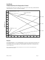
The following chart defines how the chilled water reset scheme operates when utilizing UPPER SETPOINT,
LOWER SETPOINT, and VSP in the SYSTEM VARIABLES.
UPPER SETPOINT = 55.0
55
ECHW SYSTEM TEMP
54
53
VSP = 80%
52
51
T
E
M
P
(°F)
50
VSP = 50%
49
48
LOWER SETPOINT = 45.0
47
VSP = 20%
46
LCHW SYSTEM TEMP (Control Setpoint)
45
90
80
70
60
50
40
30
20
10
0
% OF LOAD
Example:
If the UPPER SETPOINT = 55°F; LOWER SETPOINT = 45°F; VSP = 50%; then the no load point would
be 50°F. ([upper – lower] * vsp ÷ 100 + lower = no load) In this example, if the ECHWT is at or above 55°F (upper
setpoint) then the control setpoint would be 45°F. If the ECHWT is at or below 50°F (no load) then the control
setpoint would be 50°F.
Note: The lower the VSP value selected will result in the most constant Leaving Chilled Water
Temperature from the chiller.
MCTS_A01-SE
Page 7