1
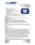
2 2.1 Introduction IK360; IK360L IK360; IK360L inclinometers sense and measure the angle of tilt (Inclination/Slope/Elevation) of an object with respect to the force of gravity. The angle is measured with the relative change in electrical capacitance. The basic principle behind this IK360; IK360L inclinometer is a Micro-Electro-Mechanical Systems (MEMS) sensor cell, that is embedded to a fully molded ASIC. A simplified version of the sensor consists of two electrodes, one is fixed, and the other is flexible (connected with spring elements). When the inclinometer is parallel to the surface of measurement, a corresponding capacitance is measured. If the sensor is tilted, the flexible electrode will change its position relative to the fixed electrode. This results in a change of the capacitance between the two electrodes, which is measured by the sensor cell. The change of the capacitance is converted to a corresponding inclination value. Absolute inclinometers identify all the points of a movement by means of an unambiguous signal. Due to their capacity to give clear and exact values to all inclinations positions, inclinometers have become one of the interesting alternatives to singleturn absolute (and incremental) encoders and a link between the mechanical and control systems. 2.2 CANopen interface CANopen is based on the Controller Area Network (CAN), that was developed by automotive industries in the 80s and is nowadays used in many industrial applications. The application protocol CANopen was introduced by the multi vendor association CAN in Automation (CiA) to ensure a full compatibility of industrial automation products. It is a multiple access system (maximum: 127 nodes), which means that all devices can access the bus. These devices/nodes are the components of the CANopen bus and in our case the node is the IK360; IK360L inclinometer. In simple terms, CANopen works as a client-server model. Each device checks whether the bus is free and if it is free the device can send messages. If two devices try to access the bus at the same time, the device with the higher priority level (lowest ID number) has permission to send its message. Devices with the lowest priority level must cancel their data transfer and wait before re-trying to send their message. Data communication is carried out via messages. These messages consist of a unique COB-ID (refer to glossary) followed by a maximum of 8 bytes of data. The COB-ID, which determines the priority of the message, consists of a function code and a node number. The node number corresponds to the network address of the device. It is and has to be unique on a bus in order to distinguish nodes and prevent any conflict of interests. The function code varies according to the type of message being sent: Management messages (LMT, NMT) Messaging and service (SDOs) Data exchange (PDOs) Predefined messages (Synchronization, Emergency messages) IK360; IK360L-CAN x Date: 08.08.2013 Page 5 of 42 Art.no. 86089 Mod. Status 292/13