1
Approved Document No. DNU6012001 Rev 1
Quantec
controller
installation and
programming manual
Quantec Installation and Programming Manual - Page 1 - Approved Document No. DNU6012001 Rev 1
index
SUMMARY OF NEW FUNCTIONS & SYSTEM ENHANCEMENTS .............................. 3
SYSTEM WIRING OVERVIEW & IMPORTANT NOTES ................................................ 4
MOUNTING THE ENCLOSURE .................................................................................... 5
CONNECTING THE PANEL ........................................................................................... 6
The Power Supply PCB ............................................................................................................ 6
Mains connection ............................................................................................................. 6
Standby battery connection ............................................................................................. 6
The Main Control PCB .............................................................................................................. 7
Connecting the network ................................................................................................... 7
PC connection ................................................................................................................. 7
Printer connection ............................................................................................................ 7
Radio pager connection .................................................................................................. 7
Auxiliary output connection ....................................................................................................7
THE QUANTEC CONCEPT ........................................................................................... 8
PROGRAMMING QUANTEC ........................................................................................ 11
Programming methods .............................................................................................................. 11
Typical programming sequence ............................................................................................... 11
Overview of access levels ....................................................................................................... 12
Access level three programming functions .............................................................................. 13
The Assignment Menu ................................................................................................... 13
The System Setup Menu ................................................................................................ 17
The Program Menu ....................................................................................................... 19
The Secure User Menu .................................................................................................. 19
APPENDICES ................................................................................................................ 20
FORMS .......................................................................................................................... 23
Quantec Device Assignment Table
Quantec Group Routing Table
Quantec Zonal Routing Table
Quantec Network Splitter Connection Record
Quantec Installation and Programming Manual - Page 2 - Approved Document No. DNU6012001 Rev 1
Summary of new functions & system enhancements
The release of our second generation Quantec controller
brings a host of system enhancements and additional
programming functions to the Quantec system, including:-
PSU fault monitoring
Custom place names
battery monitoring unit.
45 custom place names of up to 11 characters each can now
be programmed into the Quantec controller. These are in
Increased zone capacity
addition to the existing library of 40 pre-set place names
which run from 'Annexe' to 'Zone'. It should be noted that
corridor displays with a software revision number of 1.5 or
earlier will only accept 20 custom place names. If you wish
to use more than 20 you must upgrade your displays to
software revision number 1.6 or above.
Upload/Download PC programming tools
A sophisticated upload/download PC program (part no. QT707)
is now available. Copies are available from your distributor.
Automatic Day/Night mode
It is now possible to allocate the times at which the system
will automatically enter and exit night mode.
The controller’s efficient switch-mode PSU combines the
functions of a power supply unit, battery charging unit and
There are now 32 zones available for the setting up of
addressable overdoor lights and sounders (the previous limit
was 16), allowing more sophisticated "follow my leader"
light scenarios to be implemented.
Facility for Attack calls to be sent Globally or Locally
This feature operates in the same way as the existing
Emergency calls sent Globally or Locally feature, i.e. the
system can be set up to send Attack calls to All display
Groups (Globally) or only to display Groups assigned to a
certain area (Locally).
Easy conversion of existing site data
To help minimise the work required to replace old type
Quantec controllers with new ones, a facility has been
Printer/pager always on-line
included which will convert site data into the new format.
The provision of two RS232 ports on the main control PCB
This is achieved using the PC programming tools to first
allows printer and paging equipment to be connected and
used at the same time.
capture the site data normally sent to the printer with the
Print All function. This file can then be saved for later use
and converted into the new format by clicking the
Improved call message buffer
The old method of holding calls has been replaced by a new
method which allows up to 30 calls of any type to be held at
any one time. (This feature is dependent on corridor displays
having a software revision number of 1.6 or above).
Coded entry to Authorised User and Engineer modes
software's ‘Convert’ button.
ID address 'point' monitoring function
This function allows any ID address to be polled
independently. When polling the address, the relevant
device's confidence LED will flash or, in the case of an
addressable sounder, its beeper will sound at the standard
Two access levels of programmability are available at the
call rate.
Quantec controller, each with separate 4 digit push-button
access codes. The first (authorised user level) allows non-
Double address detection
critical data to be modified and is intended for use by
managers/matrons, etc. The second (engineer level)
Double addresses are now automatically detected and
incorporates all programming functions and is described in
detail later in this manual.
function which will indicate the devices which are doubly
Additional outputs
‘Replace Device’ function
There are now four open collector outputs provided for Call,
Help Required, Emergency and Attack calls. These can be
This new function allows any addressable device to be replaced
used to drive relays.
and area/group/zone details from the controller's memory.
Bigger, more informative LCD on the Quantec controller
Improved 'Reassign Device' function
The controller's display has been increased from 16x2
characters to 40x2 characters. It is now effectively split into
two parts, the left side showing the time, date and call
information; the right side continually showing the overall
status of the system and providing notification of any faults.
Individual faults are automatically scrolled (most recent first)
and can be muted if required by pressing the Accept button.
(Previously, fault information was removed from the LCD
when calls were present).
This function has been improved to allow the device type to
notified to the user via the controller's LCD. There is also a
addressed by flashing their confidence LEDs.
and re-assigned without having to delete its ID number, name
be changed.
'Clean Start' function
This function allows the controller to reset all the site data
to the factory default settings. To prevent accidental
implementation of this feature, a warning prompt and
special code is required before the action can be started.
Quantec Installation and Programming Manual - Page 3 - Approved Document No. DNU6012001 Rev 1
Important notes & system wiring overview
Important notes
• This equipment must only be installed and maintained
by a suitably skilled and technically competent person.
• This equipment is a piece of Class 1 equipment and
MUST BE EARTHED
• No responsibility can be accepted by the manufacturer or
distributors of this equipment for any misinterpretation of
an instruction or guidance note or for the compliance of
the system as a whole.
• The manufacturer's policy is one of continuous
improvement and we reserve the right to make
changes to product specifications at our discretion and
without prior notice. E&OE.
• When Quantec is powered up for the first time, the
controller may need to reset its Configuration Data to
default values. The message ‘Fit NVM Link, or ‘E’ to Abort’
will be displayed. When the NVM link is fitted the message
‘INITIALISING DATA, PLEASE WAIT’ will flash on the display.
This procedure may take up to 1 minute and MUST be
completed before Quantec will operate properly.
• The controller's power supply PCB features an Earth Fault
LED. In normal operation this will be lit red. Please note
this is not a fault as earth faults are not applicable on this
product.
System wiring overview
Quantec can be compared to a very sophisticated analogue
addressable fire alarm system where the integrity of the
wiring is of paramount importance.
As with any networked system, voltage drop can be a severe
problem, especially if the power to operate the system's
devices is taken from the network itself, as is the case with
Quantec. Another problem is the potential failure of the
entire network should the wiring fail, especially in the event
of a short circuit.
Because Quantec needs to provide considerably more power
and data down the network than an addressable fire alarm
system, it is impractical to wire Quantec in the same way (i.e.
as a continuous ring with ‘Loop Isolators’).
It is common practice within the call industry to use low
voltage signal cable. This cable is more prone to mechanical
damage / poor installation than, say, MICC cable. Therefore
some way of protecting the network against catastrophic
failure must be implemented.
Consequently our ONLY recommended method of wiring
Quantec involves the use of ‘Network Splitters’. These devices
have 6-fused ‘limbs’ for the wiring of individual sections of
the system and they provide a convenient way of wiring,
testing and protecting the system. In addition to simplifying
the wiring, the Network Splitter’s fault and power LEDs also
assist the location of installation faults.
Each network splitter has one input and one output
network connection (both UNFUSED) and six 'limb' outputs
that are FUSED.
The unfused connections are for the connection of the
network ‘Spine’ which should normally be wired in at least
1mm2 cable (e.g. twin and earth). It is important to maintain
the integrity of this part of the network since any short
circuit faults WILL cause a total collapse of the network until
the fault is rectified.
DO NOT wire any networked devices to the spine other than
Network Splitters.
The fused outputs i.e.‘Limbs’ are for the connection of
individual circuits containing networked devices. These
should be wired in four core security cable.
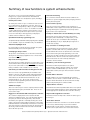
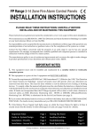
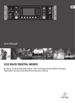
Each splitter has two indicators on its double gang fascia
plate - 'Power' and 'Fault'. 'Power' indicates that power is
being supplied to the network and 'Fault' indicates that
one of the circuits in use on that splitter has a blown fuse.
(N.B. unused circuits may have their fuses removed without
showing a fault).
No more than 64 addressable devices can be connected to
each network splitter. Consequently four splitters are
capable of accommodating an entire system. However, for
larger systems and for convenience it is recommended that
more should be used.
There are many different cabling scenarios with varying
lengths of cable and numbers of system devices attached to
each spine/splitter combination(s), all capable of operating
with different levels of simultaneous calls.
For this reason only one general purpose scenario is
explained in detail. This is described in our Quantec General
Purpose Wiring Instructions (document no. DNUQ171717)
and we strongly recommend you read this document before
proceeding.
Power
Fault
Network Splitter
A Quantec Network Splitter
Quantec Installation and Programming Manual - Page 4 - Approved Document No. DNU6012001 Rev 1
Q
Mounting the enclosure
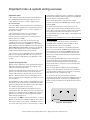
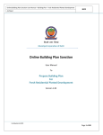
The controller is supplied with a plastic hinged lid, a metal
back box and three separate PCBs, the relative location of
which is indicated in Figure 1 below.
Figure 1 : PCB layout
PSU earth strap
Chassis earth point
PL1
Main Control
PCB
PL5
PL1
Power Supply
PCB
PL1
PCB
Retaining
Screw
PCB
Retaining
Screw
PL1
Push
tab and
gently
lift cable
The controller must be sited internally in an area not subject
to conditions likely to affect its performance, e.g. damp,
salt-air, water ingress, extremes of temperature, physical
abuse, etc. The liquid crystal display on the enclosure's front
should ideally be situated at eye level.
The controller can be surface or semi-flush mounted (see
figure 3, bottom right) and can be located anywhere on the
network, although it is normal practice to install it centrally
or in the manager or matron's office.
Exposing the base mounting holes
• Push the PCBs up and then forwards over the mounting
pillars taking care not to damage any of the components.
The controller's lid and base PCBs can now be removed from
site to prevent accidental damage.
Please note: The base PCBs are static-sensitive and relevant
anti-static handling precautions must be observed when
handling them. Refer to Appendix 3 for further details.
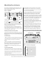
Decide carefully how the wiring will be brought into the panel
with reference to figure 2 below and remove the required
knock-outs for cable entry. Always ensure that if a knock-out
is removed, the hole is filled with a good quality cable gland.
Any unused knock-outs must be securely blanked off.
It is essential that the 230Va.c. cable comes into the
enclosure via one of the inlets at the top right hand corner
of the enclosure. For further CRITICAL information on mains
connection please refer to page 6.
Using the four mounting holes, fix the base securely onto/
into the wall. The mounting holes are suitable for use with
No.8 roundhead or countersunk woodscrews. Assess the
condition and construction of the wall and use a suitable
screw fixing. Any dust or swarf created during the fixing
process must be kept out of the controller and great care
must be taken not to damage any wiring or components.
Figure 2 : Internal view of back box (with PCBs removed)
showing mounting holes, knockouts and earthing points
To expose the controller's base mounting holes, its two base
PCBs must first be removed. It is also recommended that the
hinged lid is removed to prevent accidental damage during
the fixing process.
KNOCKOUTS FOR
LOW VOLTAGE WIRING
KNOCKOUTS
FOR INCOMING
MAINS CABLE
To remove the lid: • Take the controller out of its box and undo the two screws
on the right hand side of the lid using the allen key provided.
• Hinge the lid 180° to the left (do not overbend the
hinges).
• Disconnect the lid/base connecting cable (PL1) from the
Main Control PCB. Care should be taken when detaching
this connector to depress the telecoms-style locking tab to
prevent damage (see the inset in figure 1 above).
• Carefully remove the four M4 retaining nuts that secure
the hinges.
To remove the base PCBs: -
CHASSIS
EARTH POINT
MOUNTING
HOLE
MOUNTING
HOLE
DO NOT drill any holes for
cable entry in this shaded
area as this is where the
PCBs and back up
batteries will be located.
Figure 3: Semi-flush mounting diagram
60mm
• Ensure power has been removed from the panel and that
the PSU PCB is safe to handle (see page 6 for further details).
WALL
• Disconnect the connector cable (PL5) on the Main Control PCB.
• Pull the PSU earth strap off the spade connector at the
main chassis earth point.
• Carefully undo the PCB retaining screw located at the bottom
left hand side of the relevant PCB using a crosshead screwdriver.
Quantec Installation and Programming Manual - Page 5 - Approved Document No. DNU6012001 Rev 1
MOUNTING
HOLE
MOUNTING
HOLE
Connecting the panel
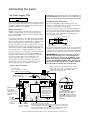
The Power Supply PCB
Primary Fuse: 20 x 5mm 1A HRC Ceramic to IEC 127 (EN60127 Pt 2).
Battery & Output Fuses: 20 x 5mm 3A F to IEC 127 (EN60127 Pt 2).
DO NOT USE ANY OTHER TYPE OR SIZE OF FUSE IN THESE POSITIONS
THIS UNIT MUST BE EARTHED
Standby battery connection
The controller’s PSU combines the functions of a power supply
unit, battery charging unit and battery monitoring unit. It is a
185-265Va.c. 50-60Hz off line switched mode PSU which stores
hazardous voltages of up to 400Vd.c.
The power supply PCB contains circuitry that not only
charges stand-by batteries, but also measures the condition
of them to protect against deep discharge.
Mains connection
One feature of this circuitry is that it allows the installer to
power the system without connecting the mains supply. For
this to work, two fully charged 12V VRLA batteries should
be connected in series, as shown below (always ensure
correct polarity connection).
DO NOT connect mains to the PSU until the installation is
complete and all the PCBs are correctly attached, the lid/
base connecting cable is in place and all retaining screws are
firmly fastened down.
battery link wire
The general requirement for the mains supply to the controller
is fixed wiring, using three core cable (no less than 0.75mm2
and no more than 2.5mm2) or a suitable three conductor system
that meets the appropriate national wiring regulations.
12V
battery
+
–
–
+
black wire
from controller
The panel should be fed from an isolating switch fuse spur,
fused at 3A. This should be secure from unauthorised operation
and be marked “CALL SYSTEM : DO NOT SWITCH OFF”. This
mains supply must be exclusive to the Quantec controller.
12V
battery
red wire
from controller
Pressing the 'Battery One Shot Button' for 2-3 seconds allows
the PCB to measure battery voltage and, if everything is okay,
to activate the system circuitry. Checking the LCD display whilst
pressing the button will report any poor battery conditions.
Correctly terminate the incoming cables as shown in figure 4
below. If required, the 5mm connector block (CONN1) can
be pulled from the PCB for ease of installation. Ensure that
the incoming mains earth is connected directly to this
connector block and NOT to the chassis earth point.
IMPORTANT: When Quantec is powered up for the first
time, the controller may need to reset its Configuration
Data to default values. The message ‘Fit NVM Link, or ‘E’ to
Abort’ will be displayed. When the NVM link is fitted the
message ‘INITIALISING DATA, PLEASE WAIT’ will flash on the
display. This procedure may take up to 1 minute and MUST
be completed before Quantec will operate properly.
The PSU PCB is connected to the Main Control PCB by a
10-Way pitch connector. This connects from PL1 on the
Power Supply PCB to PL5 on the Main Control PCB.
Figure 4 : Mains connection
Mains cable must be segregated from other cables
and should only enter the controller through either
of these two knock-outs. Good quality cable
glands must always be fitted.
PSU earth strap
Do not operate the controller
without this strap connected
Chassis earth point
Do not remove spade
OUTPUT FUSE
3AF
1A HRC
CONN1 L
N
PRIMARY FUSE
Protective cover
This cover protects
against accidental
contact with circuit
components that
may be charged
at up to 400Vd.c.
BATTERY FUSE
3AF
EARTH FAULT LED
Normally lit.
Please ignore earth faults are not
applicable on this
product.
PSU PCB
retaining screw
This must be
secured tightly
before
operation
Battery
one-shot
button
DO NOT
ADJUST
N
E
L
L
Incoming mains cable earth must
be connected to the terminal
marked
and not the chassis
earth point. (The PSU earth strap
connects the earth to the chassis
earth point).
+ -
Battery
back-up
supply
N
Hazardous voltages present LED
When lit red, hazardous voltages will be present on the components
in the shaded area of the PCB. When power is removed, this charge
is bled away. Only when you have seen the red light extinguish can
you be sure the charge has leaked away to a safe level.
Quantec Installation and Programming Manual - Page 6 - Approved Document No. DNU6012001 Rev 1
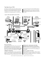
The Main Control PCB
The Main Control PCB includes all the terminals required for
the connection of the network wiring and optional system
ancillaries such as printer/paging equipment. It also features
a 4 way pitch connector for the connection of an IBM
how to wire all of the above can be found in figure 5 below.
The Main Control PCB is connected to the Power Supply
PCB via a 10-Way pitch connector (PL5) and to the Front
Panel Display and Switch PCB via an 8-way telecoms style
compatible PC for programming purposes. Information on
cable (PL1).
Figure 5 : Main Control PCB connection details
Printer
connection
Laptop
PC connection
Network
connection
Alphanumeric radio
pager connection
Refer to our Quantec General Purpose
Wiring Instructions (doc no. DNUQ171717)
for detailed wiring information.
'limb' wiring
DP877QA
pager
Serial
interface
lead
Connector
lead (supplied
with QT707
software kit)
IBM compatible PC running
Windows 95/98/2000
QT600S
wall socket
to 'next
splitter
Serial
interface
lead
DP874QA
Radio transmitter
QT603 Network Splitters
to 'next
splitter
QT600S
wall socket
'limb' wiring
White
Green
Blue
Black
White
Green
Blue
CTS 0v Rx Tx
CTS 0v Rx Tx
Nework
'spine' wiring
see bottom of page for details
(can be used for tone only paging)
{
Black
Auxiliary output
connections
+
+24V OP1 OP2 OP3 OP4 OP5 0V
CONN1 PL3
PRINTER/PC
–
–
CONN2
PAGER
PL8
Volume pot
(turn to increase or
decrease buzzer
volume)
Lid/base connecting cable
(connects to PL1 on front Panel
Display and Switch PCB)
PL1
FRONT
PANEL
CONNECTOR
+
CONN5
NETWORK
CONN4
OUTPUTS
NVM
(non-volatile
memory - holds
site specific data)
PCB retaining
screw (must be
secured tightly
before operation)
Two common network
connections are
provided for
ease of wiring
NVM
UNLOCKED
1C9
NVM
PLK1
LINK TO
UNLOCK NVM
NVM unlocked
LED (lit amber
when PLK1
programming
link fitted)
Printer connection
A standard 80 column RS232 printer can be connected to the
PCB via a QT600S wall socket as shown. Most will work
(although this cannot be guaranteed) provided they are set
up as follows: data word = 8 bit; stop bit = 1; baud rate = 9600;
parity = none. If in doubt, a pre-tested Printer Kit c/w printer,
wall socket and interface lead is available, part no. QT600P.
PSU
Programming link
(when fitted, allows
site specific
programming data
to be edited)
PSU/Main Control
PCB connecting
cable (connects to
PL1 on PSU PCB)
Alphanumeric radio pager connection
Alphanumeric radio paging can be achieved using a
DP874QA transmitter connected to the PCB via a QT600S
wall socket as shown above (the DP874QA includes a wall
socket and interface lead). Pagers are also available, part
no. DP877QA.
Laptop PC connection
Auxiliary output connection
If you wish to programme Quantec using its upload/download
software, an IBM compatible PC running Windows 95, 98 or
2000 should be connected to the PCB as shown. Our QT707
software kit includes a lead with a 9-way serial port connector.
A typical application for the controller's auxiliary outputs is
to introduce tone only paging equipment onto the system,
to drive strobes or interface to other systems. See Appendix
4 for typical wiring information.
Quantec Installation and Programming Manual - Page 7 - Approved Document No. DNU6012001 Rev 1
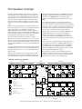
The Quantec Concept
10-17) are assigned as members of one Area (Area A) and
all displays in West Wing (devices 2 and 3) are assigned as
members of one Group (Group 1). A similar scenario
applies to the East Wing, the Central area and the South
Wing.
In today’s modern healthcare environments, it is usual for
staff in nursing homes and hospitals to be responsible only
for certain areas of the building dependent on factors such
as layout, type of care, staff to patient ratios, etc. Thus, in
order to create an effective call system, all call points and
monitoring points within the building need to have their
messages “routed” only to the displays relevant to certain
staff.
It is virtually impossible for conventional call systems to
meet this requirement without the inclusion of expensive,
multi-zone 'repeater' panels and extremely careful planning.
Basic addressable call systems can achieve this a little more
easily but, as they are still essentially 'dumb' systems, many
fail to take into account the varied needs of the user.
Quantec does this by setting all the call points within one
part of the nursing home as one area, and all the call points
within another part of the building as another area.
Similarly, displays are set as members of different groups,
again dependent on their location within the building. The
object of grouping devices in this manner is to allow simple
routing equations which describe how messages are
directed around the system by the Quantec controller.
Quantec, with its four levels of call, built-in datalogger and
sophisticated data protocol, is much more flexible. For
example, it is possible to programme the addressable
overdoor light outside the West Wing (device 7) so it will
indicate when a call has been made from any calling devices
in Area A.
However, before being set as members of an area or group,
all devices on the network (apart from ancillary devices such
as slave overdoor lights and ceiling pulls), need to be given a
unique address (ID) number so they may be identified by the
controller.
Therefore, just as the calling devices in the West Wing need
to be assigned as members of an Area and Displays in the
West Wing need to be assigned as members of a Group,
each addressable overdoor light needs to be assigned as a
member of a Zone. (If used, Addressable Sounders should
also be assigned as members of a Zone).
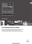
The example illustration of a nursing home (below) explains
in simple terms how the above concept can be applied. The
method of routing shown is one of several variations which
may be set up.
By referring to the nursing home installation plans it is
possible to determine the Area, Group and Zone sets for the
entire site, and plot them onto a Device Assignment Table,
similar to the one shown on the following page:
All calls made from Bedrooms 1 to 6 and Lounge 1 will be
dealt with by staff located in the West Wing. Therefore,all
the call points/monitoring points in the West Wing (devices
Example nursing home illustration
WEST WING
Bedroom1
10
C
C
Bedroom2
13
CENTRAL
Lounge 1
C
C
EAST WING
Bedroom7
Bedroom3
15
17
C
C
C
26
7
M
AOL
D
L
11
L
L
8
C
Bedroom8
Bathroom 1
18
C
C
19
C
C
Bedroom9
20
C
21
C
C
AOL
L
L
L
L
L
25
2
M
L
L
14
C
C
16
3
C
Bedroom4
L
27
C
Bedroom5
D
Staff Room
22
C
C
L
4
C
C
C
L
23
C
M
24
C
D
12
L
C
C
Reception
Bedroom6
Nursing Station
Bedroom11
Bedroom12
Bedroom14
Lounge 2
Bedroom15
Bedroom16
D
Bedroom10
C
Call Point
M
Monitor Point
C
L
AOL
D
Ceiling Pull
Slave Overdoor Light
Managers
Office
28
9
M
AOL
1
NC
Kitchen
Quantec Controller
30
31
32
33
C
C
C
C
L
L
L
L
L
L
37
L
Addressable Overdoor Light
Display Unit
5
29 C
6
34
35
C
C
D
NC
Entrance
C
Bedroom17
C
Nursing Station
Bedroom18
SOUTH WING
Quantec Installation and Programming Manual - Page 8 - Approved Document No. DNU6012001 Rev 1
M
36
C
C
Bedroom19
Quantec DEVICE ASSIGNMENT TABLE
DEVICE
Number
Type
Call Point
AREA
Display
GROUP
Addressable
Overdoor Light
ZONE
PLACE DESCRIPTION
Name
Number
1
MAIN
4
Display
NET1
2
D
1
Display
1
3
D
1
Staff Room
1
4
D
2
Display
2
5
D
3
Display
3
6
D
4
Display
1D
7
Z
1
O D Light
1
8
Z
2
O D Light
1
9
Z
3
O D Light
6
10
C
A
Bedroom
WW1
11
M
A
Exit
WW1
12
C
A
Bedroom
WW4
13
C
A
Bedroom
WW2
14
C
A
Bedroom
WW5
15
C
A
Lounge
WW1
16
C
A
Bedroom
WW6
17
C
A
Bedroom
WW3
18
C
B
Bedroom
EW7
19
C
B
Bathroom
EW1
20
C
B
Bedroom
EW8
21
C
B
Bedroom
EW9
22
C
B
Bedroom
EW10
23
C
B
Bedroom
EW11
24
C
B
Bedroom
EW12
25
M
B
Exit
EW1
26
M
C
Exit
CEN1
27
C
C
Annexe
CEN2
28
M
C
Entrance
CEN3
29
C
D
Kitchen
1
30
C
D
Bedroom
SW14
31
C
D
Lounge
SW2
32
C
D
Bedroom
SW15
33
C
D
Bedroom
SW16
34
C
D
Bedroom
SW17
35
C
D
Bedroom
SW18
36
C
D
Bedroom
SW19
37
M
D
Exit
SW1
Max. no. of devices = 255; Max. no. of areas = 26; Max. no. of groups = 32; Max. no. of zones = 32
D = Display; Z = Addressable Overdoor Light or Sounder; C = Call Point; M = Monitoring Point
The Device Assignment Table can be used as reference aid when
programming the system. However, before programming can
begin, the day-to-day requirements of the call system must be
ascertained from the client to enable the routing relationships
between the various Areas, Groups and Zones to be
determined.
The Requirement: At night, when fewer staff are on duty,
calls need to go to different nursing stations than during
the day, i.e. from unmanned nursing stations to staffed
locations.
The Solution: Two different routes can be programmed
into Quantec - a primary route (to specify which call areas
sound where during daytime hours) and a night route (to
specify which call areas sound where at night). Quantec
can be programmed to enter and exit night mode either
automatically or manually by an authorised member of staff.
Quantec Installation and Programming Manual - Page 9 - Approved Document No. DNU6012001 Rev 1
For the example nursing home highlighted earlier, it may be
decided that the routing relationship between Areas and
Groups needs to be as follows:
AREA A
West Wing
Calling
Devices
AREA B
East Wing
Calling
Devices
AREA C
Central
Calling
Devices
AREA D
South Wing
Calling
Devices
GROUP 1
West Wing
Displays
GROUP 2
Central
Displays
GROUP 3
East Wing
Displays
GROUP 4
South Wing
Displays
The displays in
Group 1 need to
respond to calls
from Area A
during the day
and remain
silent at night
although all calls
will still be
displayed in
Group 1.
The display in
Group 2 needs
to respond to
calls from Area
B during the day
and remain
silent at night
although all
calls will still be
displayed in
Group 2.
The display in
Group 3 needs
to respond to
calls from Areas
B and C during
the day and, as
the main
evening nursing
station, it needs
to sound when a
call is made
from Areas
A,B,C or D at
night.
The displays in
Group 4 need to
respond to calls
from Area D
during the day
and sound
when a call is
made from area
D at night as the
wing is manned
24 hours a day.
The Requirement: In addition to standard slave overdoor
lights positioned outside rooms a method of visually
guiding staff along small off-shoot corridors to the source
of a call is also required.
The Solution: Quantec’s addressable overdoor lights can be
programmed to respond to calls from any area(s) just as
groups of Displays can. For instance, the addressable
overdoor light in Zone 1 of the example illustration needs
to respond to all calls from Area A. It is possible to
programme a series of strategically placed addressable
overdoor lights to lead staff directly to the source of a call
by putting up to eight areas in the Area equation, i.e.
'Follow My Leader' lights.
For each Zone there are, in fact, two equations - one for
Areas and one for Devices. The device equation would be
used if an addressable overdoor light was positioned
outside a room with more than one call point or where (say,
in a refurbishment) only two wires are available. By
including the device numbers of the relevant call points
within that room in the device equation, the addressable
overdoor light will illuminate when a call is made.
Once the routing relationships between Zones, Areas and (if
applicable) devices has been decided, they should be
programmed into a Zonal Routing Table (see example
below).
PRIMARY (DAY) ROUTE
NIGHT ROUTE
(It should be noted that, in night mode, displays not programmed to sound when a
call is made will still display ALL calls on the system visually).
Quantec
ZONE
In night mode, any call point which has a 'call follower sounder' installed (optional)
and is in the 'presence' state will indicate that another call has been initiated by
emitting a soft tone.
The Requirement: Although each wing of the nursing
home will be staffed independently, if a call is not answered
within a certain period of time, it must be automatically
flagged elsewhere in the building to ensure a response.
Similarly, if a nurse has to leave her nursing station, she
must be able to manually divert calls in her absence.
The Solution: Quantec can be programmed to divert calls
from one group of displays to groups located elsewhere,
either automatically (after a pre-determined time) or
manually. For instance, if any call signalled to Group 1
displays is not answered after 1-8 minutes (adjustable) it can
be programmed to automatically divert to displays in, say,
Groups 2 and 3. Once the routing relationships between
Areas and Groups has been decided they should be
programmed into a Group Routing table, similar to the
example shown below (for details of how to set the timeouts for automatic divert, refer to the 'Programming
Quantec' section).
Quantec GROUP ROUTING TABLE (max. 8 areas/groups per set equation)
GROUP
PRIMARY AREAS
NIGHT AREAS (BEEP)
1
A
2
B
3
B, C
A, B, C, D
4
D
D
DIVERT TO GROUPS
2, 3
ZONAL ROUTING TABLE (max. 8
AREA EQUATION
1
A
2
B
3
D
areas/devices per equation)
DEVICE EQUATION
The Requirement: Although standard patient and 'help
required' calls should be flagged in each independently
staffed wing, to ensure a swift response to any emergency
or attack calls, these should be flagged throughout the
nursing home as soon as they are made.
The Solution: Emergency and/or attack calls can be sent
out either locally or globally during the day, dependent on
each client’s specific requirements. If 'Local' is chosen, the
calls are sent only to the display Groups set up in the routing
table. Alternatively, if 'Global' is selected, the calls are sent
out to every display on the network. (Refer to the
'Programming Quantec' section beginning on the next page
for further details).
The Requirement: To assist in the efficient running of the
nursing home and to combat any accusations from patient’s
relatives that calls are not being answered quickly enough, a
reliable form of evidence is required to prove that nurses
are attending to patients as quickly as possible.
The Solution: Quantec’s network controller includes a
built-in datalogger which, if selected, will record all
activities on the call system, including calls, resets and
faults.
Quantec Installation and Programming Manual - Page 10 - Approved Document No. DNU6012001 Rev 1
Programming Quantec
Before programming commences, we recommend you
read 'The Quantec concept' section on pages 8 to 10.
Commissioning is the most critical part of the installation
and a basic understanding of how Quantec works and
the thinking behind it is essential.
Programming methods
The controller can be programmed using two methods:(1) Using its front panel buttons and LCD display
Although time consuming, all aspects of programming can
be undertaken using this method and no other piece of
equipment is required.
(2) Using the Quantec upload/download software
Allows quick and easy input of data and routing
arrangements via an IBM compatible PC. This method is
much quicker than method 1 and provides the added bonus
of allowing off-site programming if the relevant details are
available and the archiving of programming information for
future reference.
Only the first method is covered in detail in this manual.
Information on how to programme Quantec using its
upload /download software can be found in the separate
instructions and help files supplied with the software.
The efficiency with which the programming function is
carried out depends on: •
The accuracy of information received regarding the
wiring and devices fitted.
•
The freedom of the installation from faults and errors.
•
The completeness of the information received from the
client/specifier as regards text information and the
manner in which the equipment is to operate.
The only factor normally within the control of the
programmer is the final item and even if this is done
perfectly, the quality of the installation will always be based
upon the quality of the first two factors. To help ensure
that the information received is as complete as possible, we
recommend the installing contractor is provided with the
following documentation before starting the job:-
IMPORTANT: When Quantec is powered up for the first time,
the controller may need to reset its Configuration Data to
default values. The message ‘Fit NVM Link, or ‘E’ to Abort’
will be displayed. When the NVM link is fitted the message
‘INITIALISING DATA, PLEASE WAIT’ will flash on the display.
This procedure may take up to 1 minute and MUST be
completed before Quantec will operate properly.
(1) Power up the system and assign the devices on the
limbs by whichever method you prefer. Experience shows
the easiest way to do this is using the controller's AutoScan
function. This sequentially assigns the next available ID
location to unassigned devices as they are operated and
allows the system to be programmed very quickly.
(Refer to programming subsection 1.2).
Hint: When autoassigning the system, plan your route around the
building on a drawing, marking on it the device numbers you
anticipate will be assigned to each networked device. It is advisable to
assign each limb one at a time, periodically stopping the autoassign
function to check that a particular device is programmed as
anticipated. A handy way of doing this is to programme a display and
then press the A button which will display its ID number. Whilst the
autoassign function is active, pressing a call button on any unassigned
device will automatically assign the next available device number to it
- beware of plumbers pressing buttons at the far end of the building!
(2) Verify that the devices are programmed correctly by
checking the last assigned number at the controller or by
using the display device function. Once a device is
programmed, it retains its ID even when power is removed.
If programmed by mistake, you must reset the ID to
unassigned by shorting the two Reset ID pins on the
networked device PCB whilst it is powered up.
Note: Once a device's ID number has been reset, it enters the
unassigned state. At this point the old ID number must be deleted
from the controller as it will try and scan for the device and not be
able to find it. See Editing Existing Devices (section 1.3)
(3) Print off a list of devices. If you don't have a printer you
must write this information down by scrolling through the
device assignment table at the controller. This initial list (if
you are using a printer), will show no names attached to the
devices and can be given to the client so they can write
down what they wish to call each device.
Note: 45 custom and 40 pre-set place names are available - see
editing custom texts (section 1.4) for details.
(4) Discuss with the client all the routing options for calls
(i.e. night mode operation, splitting of network into
manageable areas, the routing of calls to different displays,
divert /autodivert functions, timeouts, logging options, etc).
Most options are highlighted in the Quantec Concept
section of this manual.
•
Quantec General Purpose Wiring Instructions
(approved document no. DNUQ171717)
(5) Programme in the names and operating modes, routing
tables, etc, as agreed with the client (refer to programming
•
Quantec Pre-Commissioning Instructions
(approved document no. DNUQ1818PRE).
subsections 1.3 - Editing Existing Devices, 1.5 - Assigning or Editing
Area/Group Relationships, 1.6 - Setting up Addressable Overdoor
Lights / Sounders, 1.7 - Editing custom texts and section 2 - The
System Set-Up Menu).
Both of these documents have sections in them that should
be completed by the installing contractor prior to handover.
Typical programming sequence
A full explanation of Quantec’s programming functions can
be found on the remaining pages of this manual. The actual
commissioning sequence used will vary depending on the
information available and personal preference. However
we recommend it follows a similar pattern to that described
in the next column:-
Note: All Call Points / Monitoring Points default to Area A; all Displays
default to Group 1 and all Addressable Overdoor Lights / Sounders
default to Zone 1. Group 1's routing equation defaults to Area A,
Group 2’s routing equation defaults to Area B, etc. Zones have no
routing data by default.
(6) Print off a full list of the system devices and programming
set-up data and verify it is as planned. Correct any errors as
necessary. Print and keep a copy of the set-up for reference.
Hint: If you don’t have a printer, the above lists must be derived
manually by scrolling through the controller and writing the list down.
Quantec Installation and Programming Manual - Page 11 - Approved Document No. DNU6012001 Rev 1
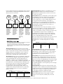
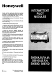
Overview of access levels
Three access levels are available at the Quantec controller:
general user (access level 1), authorised user (access level 2)
and engineer (access level 3).
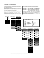
The menu options available are shown on the menu tree below
and are described in detail in the following documents:-
All programming functions are located in access level 3 and
can be accessed by inputting a four digit code at the controller
(default = 3 3 3 3). The controller will automatically exit access
level 3 after a period of 1 hour has elapsed.
V
ACCESS LEVEL 2
2
2
2
2
Quantec Users Guide (DNUQ111111)
Quantec Manager/Matron's Guide (DNU6012005)
Quantec Programming Manual (i.e. this manual refer to the subsection number below each menu
option for detailed information on that feature)
It should be noted that The 'NVM' link (located on the Main
Control PCB) must be fitted during the programming process.
This unlocks the non-volatile memory on the controller and
allows site specific data to be modified.
Entry to access level 2 requires the input of a different code
(default = 2 2 2 2) whilst entry to access level 1 does not
require an access code. Access level 2 will automatically exit
after 5 minutes without a key press.
ACCESS LEVEL 1
Access level 1:
Access level 2:
Access Level 3:
ACCESS LEVEL 3
3
3
3
3
or as programmed
or as programmed
}
}
Setup Divert
Set Day/Night
Set Day/Night
A
=
ACCEPT
1
=
1
Exit Menu
Output Log
Output Log
V
=
SCROLL UP
2
=
2
V =
SCROLL DOWN
3
=
3
E
ESCAPE
4
=
4
Quantec controller keys
4.1
Set Date
Set Date
4.2
Set Time
Set Time
Net. Reset
Net. Reset
=
4.3
Program
Sub Menu
4.4
Program Menu
A
Assignment Menu
System Setup Menu
System Setup
A
Set Assignment
A
New Device
1.1
4.5
Display Device
Set Time Outs
Print All
Set AL2 Code
3.2
Print Devices
Set AL3 Code
Existing Device
1.3
Replace Device
2.3
Set Attack Reset
1.4
Setup Group
2.4
3.4
Print Zones
1.2
2.2
3.3
Print Groups
AutoScan
2.1
3.1
Set Call Reset
1.5
Setup Zone
2.5
3.5
Setup Logger
1.6
Edit Cust Texts
2.6
Emergency G/L
1.7
Send Cust Texts
2.7
1.7
Clean Start?
Attack G/L
2.8
RadioPager
2.9
Auto Night Mode
2.10
Monitor Point
2.11
Double Address
2.12
Quantec Installation and Programming Manual - Page 12 - Approved Document No. DNU6012001 Rev 1
1.8
Access Level 3 Programming Functions
1.0 The Assignment Menu
The Assignment Menu allows the introduction of
unassigned devices onto the network and the setting up of
routing arrangements for areas, groups and zones. It also
allows the parameters of any existing device, including its
name, to be changed.
1.1 Assigning Individual Devices
Move through the menus to the Assignment Menu and
accept the New Device prompt. The next unused ID
number will be presented:New Device
Number to be 002
This can be altered if required using the scroll keys, but it is
usual to accept this prompt. (Network devices can be
assigned any ID number from 2 to 255. Address 1 is always
allocated to the Quantec controller). After pressing the
Accept key, the next prompt is to activate the new device:Activate Device
002 or ESC
When the unassigned device is activated, the controller will
respond by showing the type of device in code form, e.g.
Device 002 CLPT
Select Area A
(CLPT = Call Point; DISP = Display; MNPT = Monitoring
Point; ZNID = Addressable Overdoor Light/Sounder)
Use the scroll and Accept keys to enter the appropriate
Area, Group or Zone with reference to the 'Device
Assignment Table' on page 23 onwards). Once the relevant
Area, Group or Zone has been accepted, a location prompt
will appear:-
1.2 Assigning Multiple Devices
Assigning many individual devices using the 'New Device'
function can be very time consuming. Therefore, an
'AutoScan' method is available for assigning multiple
devices.
Move through the menus to the Assignment Menu and
Accept the 'Autoscan' prompt. The controller is now waiting
for a call from any unassigned device:AutoScan Mode
Waiting for call
Activate the first unassigned device in the sequence to be
programmed, at which point the controller will assign the
next available ID number from 2 to 255. (Address 1 is always
allocated to the controller).
In Autoscan mode the Area, Group or Zone membership and
location description data is not entered immediately.
Instead all outstanding devices can be activated sequentially.
As each device is activated it is assigned an ID number
automatically and, for reference purposes, the last device ID
number is displayed on the controller.
HINT: When programming a site with many devices, it is
recommended you keep a list of each ID number as each
device is activated and check at regular intervals with the
controller that the last ID numbers entered correspond. If
they do not, either a mistake has been made or someone has
operated an unassigned device elsewhere in the building. (If
this is the case, refer to sections 1.3 - Editing Existing Devices,
1.4 - Resetting a Device ID Number and 3.1 - Display Device)
When the Autoscan sequence is complete exit the Autoscan
menu. At this point all assigned devices have default set
memberships and no location descriptions. To add/change
these refer to section 1.3.
Device 002 CLPT
-----------
Using the scroll and Accept keys, the device can now be given
a place name from the list of locations (see Appendix 1 for a
list of Quantec's 40 pre-set place names and note that it is also
possible to program up to 45 custom place names using the
'Edit Cust Texts' function described in section 1.7). On pressing
the Accept key, your choice will be confirmed, e.g.
Device 002 CLPT
TV Room
----
By using the scroll and Accept keys, four single
alphanumeric characters can now be tagged onto the end of
the place name.
All four terms must be accepted, even if they are blank (e.g.
a TV room in the East Wing could be TV Room EW01).
When the final character has been accepted, the “Assign
New Device” prompt reappears. Note, exiting this option
before the final character has been accepted will cancel the
description change.
Quantec Installation and Programming Manual - Page 13 - Approved Document No. DNU6012001 Rev 1
1.3 Editing Existing Devices
1.4 Replacing a faulty device
The parameters of any device already on the system can be
reassigned at any time. Alternatively, devices may be
temporarily disabled (for maintenance purposes) or deleted
from the system altogether. One of the prime uses of the
'Existing Device' function is to change the default (blank)
settings given to devices entered onto the system via the
Autoscan facility.
This new maintenance function allows you to replace a faulty
device with a new one without having to delete its name,
location and area, group or zone details from the system.
To edit, move through the menus to the Assignment Menu
and accept the 'Existing Device' prompt. The details of one of
the devices on the system will then appear, e.g:Device 002 CLPT
(the type of device, location and set descriptions may
vary depending on the parameters previously assigned)
Use the scroll keys to select the ID number of the device you
wish to change. A number of options will then appear, e.g:Device 002 ReAss
Del Disab or Esc
Use the keys to either reassign the parameters of the device,
delete it from the system or disable it. (Please note, if the
device has previously been disabled, an 'Enable' option will
appear). If the "ReAss" prompt is accepted, the controller
responds by showing the type of device in question in code
form, e.g:Device 002 CLPT
Select Area A
To execute, select the 'Replace Device' prompt from the
assigment menu. The controller will respond with a
message similar to the one below:Device 002 CLPT
Use the scroll keys to select the ID number of the device you
wish to replace and press accept. Depending on the ID number
you have selected, the following message will appear:Activate Device
002 or Esc
Activate the new device and await confirmation that it has
been assigned. To check the replaced device's details are as
expected, use the 'Existing Device' function described in
section 1.3.
(CLPT = Call Point; DISP = Display;
ZNID = Addressable Overdoor Light or Sounder)
Use the keys to enter the appropriate Area, Group or Zone
with reference to the 'Device Assignment Table' on page 23
onwards. Once the relevant Area, Group or Zone has been
accepted, a location prompt will appear, e.g:Device 002 CLPT
-------------
Using the scroll and Accept keys, the device can now be
given a place name (see Appendix 1 for a list of Quantec's 40
pre-set place names and note that it is also possible to
program up to 45 custom place names using the 'Edit Cust
Texts' function described in section 1.7). On pressing the
Accept button, your choice will be confirmed, e.g:Device 002 CLPT
TV Room
----
By using the scroll and Accept keys, four single alphanumeric
characters can now be tagged onto the end of the location.
All four terms must be accepted, even if they are blank (e.g.
a TV room in the East Wing could be TV Room EW01).
Exiting this option before the final character has been
accepted will cancel the description change. When the final
character has been accepted, the “Assign New Device”
prompt reappears:Device 002 ReAss
Del Disab or Esc
Additional devices can now be edited, or to return to the
Assignment Menu, press Escape.
Quantec Installation and Programming Manual - Page 14 - Approved Document No. DNU6012001 Rev 1
1.5 Assigning or Editing Area/Group Relationships
In order to route Areas (calling devices) to relevant Groups
(displays), routing equations must be programmed into the
Quantec controller. Move through the menus to the
Assignment Menu and Accept the 'Setup Group' prompt.
The following prompt will be displayed:
Select Group 001
Pri Nite Div Esc
To set up or change the primary (Day) equation for Group 1
use the scroll keys to highlight "Pri" and press Accept. This
equation describes to which Area(s) of calling devices the
Group of displays will respond when Quantec is in day mode.
Depending on data already entered, the following will appear:
Grp 01 Pri Mode
A
(Group 1 displays default to Area A; Group 2 to
Area B, etc. These may be altered to suit the system).
Use the scroll and Accept keys to enter the appropriate
Area(s) with reference to the 'Group Routing Table' on page
26. Up to eight areas can be selected for a group. All eight
terms must be accepted, even if they are blank. Pressing
escape before this process is complete will abort editing
without making changes.
When the eighth term has been accepted the Select Group
prompt will again be shown, e.g:-
1.6
Setting up Addressable Overdoor Lights and
Addressable Sounders
To route a call to the relevant Addressable Overdoor Light(s)
or Sounder(s), Zone equations must be programmed into
the system. Move through the menus to the Assignment
Menu and accept the 'Setup Zone' prompt. The following
prompt will appear:
Select Zone 001
Areas / Devices
Use the scroll and accept keys to enter the appropriate
Areas/Devices with reference to the 'Zonal Routing Table' on
page 27. The Zone equation describes to which Areas and/
or devices the Zone will respond to in both primary (day)
and night mode.
NOTE: Addressable overdoor lights and sounders can include
both areas and individual calling devices in their routing
equations. By default these Equations are blank. This
means addressable overdoor lights and sounders will not
function until their routing equations have been defined.
A maximum of eight areas can be assigned to each group.
All eight terms must be accepted, even if they are blank.
Pressing escape before this process is complete will abort
editing without making changes. In night mode,
Addressable Overdoor Lights and Sounders are silent.
Select Group 001
Pri Nite Div Esc
To set up or change the Night equation for Group 1 use the
scroll buttons to highlight "Nite" and press Accept.
When in night mode, Quantec routes all Areas to all Groups
but only the display Groups that are programmed to beep in
the 'Night' mode will do so. Use the scroll and Accept keys
to enter the appropriate Area(s) with reference to the
'Group Routing Table' on page 26. All eight terms must be
accepted, even if they are blank as pressing escape before
this process is complete will abort editing without making
changes.
When the eighth term has been accepted the Select Group
prompt will appear again, e.g.
Select Group 001
Pri Nite Div Esc
To set up or change the Divert equation for Group 1 use the
scroll keys to highlight "Div" and press Accept.
This equation describes where calls from the selected Group
should be diverted to if a call has not been accepted before
a pre-determined time has elapsed or manual divert has
been selected from the Display menu. By default, Divert
equations are blank (i.e. divert will not operate). Use the
scroll and Accept keys to enter the appropriate Area(s) with
reference to the 'Group Routing Table' on page 26. All
eight terms must be accepted, even if they are blank.
Pressing escape before this process is complete will abort
editing without making changes.
Quantec Installation and Programming Manual - Page 15 - Approved Document No. DNU6012001 Rev 1
1.7
Editing and sending custom texts
1.8
Clean Start
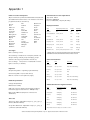
Up to 45 custom place names* of up to 11 characters each
can be added to Quantec's library of 40 pre-set place names
Selecting this function forces the controller to reset all site
(see Appendix 1 for a listing of the pre-set place names).
implementation of this feature, a warning prompt and
(the flashing text on the second line may vary
depending on the parameters previously assigned)
Use the scroll and accept keys to select the custom text field
you wish to change. On pressing the accept key you will be
able to type over the existing text with up to 11 alphanumeric characters using the scroll, accept and escape keys.
To help speed up the text entry process, in addition to upper
and lower case letters A to Z, numbers 0 to 9 and symbols / : and @, Quantec's text editing facility has a number of
special characters, as listed below:-
C
E
This clears the character you have selected and ALL
characters to the right of it.
This allows you to select the end input character on a
particular field, i.e. SURGERY E . When accepted,
this saves you from having to enter blank characters
all the way to the end of a text field.
D
This deletes the character you have selected and moves
ALL text to the right of it one position to the left.
I
This inserts one space BEFORE the character you have
selected
Move through the menus to the Assignment Menu and
accept the 'Clean Start?' function. The following prompt
will appear:
Clean Start?
Enter code?
If you wish to proceed, the following sequence of keys
should be pressed:-
V
Edit Text 01
Custom 1
special code is required before the action can be started.
V
V
To add or edit a custom name, move through the menus to
the Assignment Menu and accept the 'Edit Cust Texts'
function. The following prompt will appear:
data to the factory default settings. To prevent accidental
A
When the final key is pressed, the following message will
appear for approximately three seconds:All data will be
lost! Continue?
Pressing the accept key before the above message
disappears will instigate the clean start process. Depending
on the amount of data stored, this could take some time.
When the final character has been entered, the text on the
second line will again begin to flash, e.g:Edit Text 01
Surgery
(the flashing text on the second line will obviously
vary depending on the text you have entered)
Use the scroll keys to add/edit any additional custom place
names or press escape to return to the previous menu.
To add the newly programmed custom names to Quantec's
40 pre-set place place names you must send them to the
Displays' memories. To do this, move through the
Assignment Menu to the 'Send Cust Texts' function and
press accept. The following message will appear:Sending Texts
Please Wait
When the sending process is complete, the controller will
automatically return to the assignment menu. The renamed
custom text fields will now be available to the appropriate
device naming functions (e.g. 'New Device' and 'Existing
Device').
* It should be noted that corridor displays with a software
revision number of 1.5 or earlier will only accept 20 custom
place names. If you wish to use more than 20 you must upgrade
the displays to software revision number 1.6 or above.
Quantec Installation and Programming Manual - Page 16 - Approved Document No. DNU6012001 Rev 1
2.0 The System Setup Menu
The System Set Up menu allows you to tell the Quantec
controller specific details about how the system will work.
2.1
Setting 'Time Outs' for Call Divert and Call
Accept arrangements
This utility allows you to tell Quantec the time that should
elapse before a call is diverted from one group of displays to
another or an unanswered 'accepted' call returns to displays.
On selecting the 'Set Time Outs' prompt, the following
window will appear:
Divert: 1 mins
Accept: 1 mins
Use the scroll and accept keys to enter the appropriate Time
Out figure. The range for each facility is 1 to 8 minutes in
steps of 1 minute. Any changes will be saved automatically.
2.2
Setting the Access Level 2 Code
This option allows you to change the four digit access code
for Access Level 2 (this can be any combination of the 1, 2
and 3 keys). On selecting the 'Set AL2 Code' prompt, the
following window will appear:
Access Level 2
Code :
2.5
Setting the 'Call Reset' Code
This utility allows Quantec's four digit 'Call Reset' code to be
entered or changed (this can be any combination of the
scroll up, scroll down and accept keys). On selecting the 'Set
Call Reset' prompt, the following window will appear:
Set Call Reset
Code:
Enter the new code as required. When the fourth key has
been pressed the controller automatically registers the code
and returns you to the System Setup menu.
2.6
Setting up the Datalogging facility
This utility allows Quantec's Datalogging facility to be set up.
Select the 'Setup Logger' prompt and use the scroll and accept
keys to choose one of the following options:
Logging OFF
this disables the logging facility so
no events are logged or can be printed
Logging Man Only
this enables the logger to print
when manually selected to do so
Logging Man/Auto
Output on: 010
this enables the logger to print
automatically after 10, 20, 30, 40, 50,
60, 70, 80, 90 or 100 events
Enter the new code as required. When the fourth key has
been pressed, the controller automatically registers the code
and returns you to the System Setup menu.
Please note: If 'Man Only' is selected and the log record is
not printed, the datalogger's memory will fill to capacity.
When this occurs a warning message will appear on the
controller and any new events will not be logged until the
existing events have been printed.
2.3
2.7
Setting the Access Level 3 Code
This menu allows you to change the four digit access code
for Access Level 3 (this can be any combination of the 1, 2
and 3 keys). On selecting the 'Set AL3 Code' prompt, the
following window will appear:
Access Level 3
Code :
Enter the new code as required. When the fourth key has
been pressed, the controller automatically registers the code
and returns you to the System Setup menu.
2.4
Setting the 'Attack Reset' code
For systems utilising Quantec's infra-red attack call level, this
utility allows the four digit Attack Reset code to be entered
or changed (this can be any combination of the scroll up,
scroll down and accept keys). On selecting the 'Set Attack
Reset' prompt, the following window will appear:
Set Attack Reset
Code:
Setting up Emergency call routes
This option allows you to set the system up so Emergency
calls are sent to all display Groups (Globally) regardless of
how the group area routing arrangements have been set up.
On selecting the “Emergency G/L” prompt, it is possible to
scroll through the following two options:Emergency Calls
Sent: Locally
When you have selected the required option, press accept.
2.8
Setting up Attack call routes
This menu option allows you to set the system up so infrared Attack calls are sent to all display Groups (Globally)
regardless of how the group area routing arrangements
have been set up.
On selecting the “Attack G/L” prompt, it is possible to scroll
through the following two options:Attack Calls
Sent: Locally
Enter the new code as required. When the fourth key has
been pressed the controller automatically registers the new
code and returns you to the System Setup menu.
Emergency Calls
Sent: Globally
Attack Calls
Sent: Globally
When you have selected the required option, press accept to
return to the System Setup menu.
Quantec Installation and Programming Manual - Page 17 - Approved Document No. DNU6012001 Rev 1
2.9
Setting up the Radio Pager
2.11 Monitoring a network device
If radio paging equipment is connected to the controller's
RS232 paging terminal, this menu must be selected to enable
it to operate. On selecting the “RadioPager” prompt, it is
possible to scroll through the following options:-.
This function allows any ID address to be polled from the
Pager DISABLED
accepting this disables all paging
functions (no callls will be sent to pagers)
Pager ENABLED on
ATTACK & Higher
accepting this enables paging on
attack calls only
First, select the “Monitor Point” prompt from the system
setup menu. A window similar to the one below will
appear:-
Pager ENABLED on
EMERG & Higher
accepting this enables paging on
emergency and attack calls only
Pager ENABLED on
ASSIST & Higher
accepting this enables paging on help
required, emergency and attack calls
Pager ENABLED on
CALL & Higher
accepting this enables ALL levels of
call (except presence)
It should be noted that different levels of calls are not
prioritised by pagers. For example, if a standard call is
triggered followed by an emergency call, the emergency call
will not be displayed until the standard call has been
accepted and the next message called up. Calls will however
still be prioritised in the usual manner at QT608C corridor
displays, i.e. highest priority calls first.
2.10 Setting up the AutoNight Mode function
This function allows Quantec's automatic night mode
function to be enabled or disabled and for preset entry and
exit times to be programmed into the controller. On
selecting the 'Auto Night Mode' prompt, one of the
following options will appear:Auto Night Mode
Enabled? : NO
Auto Night Mode
Enabled? : YES
Use the scroll keys to select the required option and press
accept. Accepting YES enables the auto night mode
function and allows you to enter the time you want the
system to automatically enter night mode:-
controller. When polling the address, the relevant device's
confidence LED will flash or, in the case of an addressable
sounder, its beeper will sound at the standard call rate.
Device 002 CLPT
State=1 OK
Use the scroll keys to select the device ID number you wish
to monitor (do not press accept as this will perform a
network reset).
If the state field = '1 OK' : the device has been found by
the controller and its confidence LED will be lit (or, in the
case of an addressable overdoor light or sounder, its beeper
will be sounding at the standard call rate.
If the state field = '0 OK' : the device has been found by
the controller but it does not have a confidence LED or
sounder that can be switched on, i.e. the device is probably
a display.
If the state field is replaced by a message reading "No
Response": the controller cannot find a device with the ID
number you have selected.
Pressing Escape or Accept at any time will perform a
network reset and return you to the system setup menu.
2.12 Determining the location of devices which are
doubly addressed
Any doubly addressed devices on the system are automatically
flagged on the right hand side of the controller's display, i.e:DISABLED WC
Double Addressed
( 2)
The bracketed number (in this example '2') is the ID number
of the doubly addressed devices (if there are more than one
set of doubly addressed devices these will be flagged too). To
ascertain the exact location of the doubly addressed devices,
Entry time
07:30 pm
select the 'Double Address' option from the system setup menu.
Use the scroll and accept keys to select the relevant hour,
minute and am or pm. When the am/pm field has been
accepted the controller prompts you to select an exit time at
which the system will automatically return to day mode:-
A window similar to the one below will appear:Device 002 CLPT
State=1 OK
All devices with the ID address shown will be polled from
the controller and their confidence LEDs will flash or, in the
Exit time
07:00 am
case of addressable overdoor lights and sounders, their
Use the scroll and accept keys to select the relevant hour,
minute and am or pm. When the am/pm field has been
accepted the controller automatically returns you to the
system setup menu.
beepers will sound at the standard call rate.
Note: If the auto night mode function is disabled it is still
possible to manually switch night mode on/off at Access Level 2.
Pressing accept performs a network reset and returns you to
Pressing the scroll keys will move you onto the next set of
doubly addressed devices (if there are any) and their
confidence LEDs and sounders will activate instead.
the system setup menu.
Quantec Installation and Programming Manual - Page 18 - Approved Document No. DNU6012001 Rev 1
3.0 The Program Menu
4.0 The Secure User Menu
3.1
4.1
Display Device
To aid the location of network devices for diagnostic
purposes, it is possible to change the function of the
controller's LCD display to show the calling device ID
number instead of the place name.
Move through the menus to the Program Menu and Accept
the 'Display Device' prompt. The following prompt will
appear:
Display Device
Waiting for Call
On exiting this function the network resets itself in order to
remove any missed calls from the controller.
Print All
Selecting this function sends a list of all site-specific data to
a printer (if connected).
3.3
Print Devices
Print Groups
Selecting this function sends a list of all groups (displays) to
a printer (if connected).
3.5
Enter access level three and accept the 'Set Day/Night'
prompt. One of the following two prompts will appear:
Set Day/Night
Mode is: Day
4.2
Set Day/Night
Mode is: Night
Print Zones
Selecting this function sends a list of all zones to a printer (if
connected).
Output Log
This function allows information stored in the controller's
datalogger to be output to a standard Quantec RS232
printer. To execute, enter access level three and accept the
'Output Log' prompt . When printing is complete, the
controller will return to the previous menu. Please note,
this function will only work if the controller's datalogger has
been programmed to print manually (see 2.6) and a printer
is properly connected to its RS232 printing port.
4.3
Selecting this function sends a list of all network devices to a
printer (if connected).
3.4
This function allows the routing of calls to be changed from
the programmed day mode (primary) configuration to the
night mode (nite) configuration or vice versa.
Use the scroll keys to select the required option and press
accept.
When a calling device is activated the ID number of that
device will be shown on the display. (Please note, any other
displays on the system will continue to show the location of
the calling device as normal).
3.2
Set Day/Night
Set Date
This function allows the date to be programmed into the
controller. It is particularly important that the correct date
is entered if Quantec's datalogging facility is to be used. To
execute, enter access level three and accept the 'Set Date'
prompt.
Use the scroll and accept keys to select the correct day,
month and year. Pressing accept after the year has been
entered will return you to the previous menu.
4.4
Set Time
This function allows the time to be programmed into the
controller and is particularly important if Quantec's
datalogging facility is to be used. To execute, enter access
level three and accept the 'Set Time' prompt. Use the scroll
and accept keys to select the correct hour and minute.
When the minute data has been accepted you will be
returned to the previous menu.
4.5
Network Reset
This facility allows the Network voltage to be reduced to
zero in order to reset all network devices. The Network is
powered down for approximately 5 seconds. To execute,
enter access level three and accept the 'Network Reset'
prompt.
Quantec Installation and Programming Manual - Page 19 - Approved Document No. DNU6012001 Rev 1
Appendix 1
Index of location descriptions
Communication to the output device
40 pre-set names are provided as standard and are listed below.
(An additional 45 custom names of 11 characters each can be
programmed at Access Level Three).
Type: Serial - RS232
Data Rate: 9600 Baud
Protocol: 8 Data Bits, 1 Stop Bit, No Parity
Annexe
Exit
Quiet Room
Area
FireExit
Reception
Bathroom
Flat
Room
Bedroom
Floor
Shower
Conservtry
Gents WC
Sluice
Corridor
Hairdresser
Special
Dining Room
Kitchen
Disable WC
Ladies WC
Display
Laundry
Treat Room
Door
Lift
DoorBell
Drugs Cab.
Entrance
OD Light
ESMIUnit
Phone
Display Parameters
State
Display Beeper Rate (Sec)
Volume
BackLight
Normal
Off
n/a
Off
Staff Room
Unassigned/Fault
0.5 On, 7.5 Off
Soft
Steady
Toilet
Presence
Off
n/a
Steady
TV Room
Standard Call
0.5 On, 7.5 Off
Soft
Steady
Lounge
Ward
Help Req. Call
2.0 On, 2.0 Off
Soft
Steady
Meeting Rm
Zone
Emergency Call
0.5 On, 0.5 Off
Loud
As beep
Attack Call
0.1 On, 0.1 Off
Loud
As beep
Set ranges
Monitor Point
0.5 On, 0.5 Off, 0.5 On, 6.5 Off
Soft
Steady
Device Set Range : 2-255
* When there are concurrent Normal calls from Call Points
and Monitor Points the Monitor Point Call Rate is used.
Area Set Range : A-Z (26 areas of call points, default = A)
Group Set Range 1-32 (32 groups of displays, group 1
default to Area A; group 2 default to Area B etc).
Zone Set Range 1-32 (32 zones of addressable overdoor
lights / sounders, no defaults)
Equations
Group Routing Table = 3 (primary, night and divert).
Call Point Parameters
State
Rate
Lamp State
Normal
Off
-
Unassigned
0.5 On, 0.5 Off
Red / Green alternating
Presence
2.0 On, 2.0 Off
Green
Call
2.0 On, 2.0 Off
Red
Assist
0.5 On, 0.5 Off
Red
Emergency
0.5 On, 0.5 Off
Red / Green alternating
Attack
0.1 On, 0.1 Off
Red / Green alternating
Zone Routing Table = 2 (areas and devices)
Max. N° of terms in each equation 8 (eight)
Network specification
Voltage: 24v (Nominal)
Addressable Overdoor Light Parameters
Max.Current: 1.5Amp
Cable type : Refer to Quantec General Purpose Wiring
Instructions (approved document no. DNUQ171717)
Max. length: 400metres (Depends on devices and
distribution)
Time outs
Time before divert : Adjustable in steps 1, 2, 3, 4, 5, 6, 7, 8
minutes (Default 1 Minute)
Accept Time Out Period : Adjustable in steps 1, 2, 3, 4, 5, 6,
7, 8 minutes (Default 1 Minute)
State
Beeper Rate/Volume
Lamp State
Normal
As Display
As Call Point
Unassigned
As Display
As Call Point
Presence
As Display
As Call Point
Call
As Display
As Call Point
Assist
As Display
As Call Point
Emergency
As Display
As Call Point
Attack
As Display
As Call Point
The periods above are subject to a tolerance of 10%.
Quantec Installation and Programming Manual - Page 20 - Approved Document No. DNU6012001 Rev 1
Appendix 2
The Datalogging Function
Log Record Format
The first line states the time that the log output was started. After that the records are extracted from the log, oldest first,
and are downloaded to the output device in the following form: (a) date; (b) hour / minute; (c) location description; and (d)
type/level of call (displayed in easy to read columns).
Example of records as printed:
Log output on 1.10.02 at 11.05am
30/09
4:36pm
Dining Room
1 2 3 4
Call
30/09
4:39pm
Ward
WA 2 3
Call
30/09
4:40pm
Dining Room
1 2 3 4
30/09
4:40pm
Toilet
G F 1 4
30/09
4:41pm
Dining Room
1 2 3 4
30/09
4:42pm
Ward
WA 2 3
30/09
4:42pm
Toilet
G F 1 4
30/09
4:43pm
Ward
WA 2 3
30/09
4:44pm
Toilet
G F 1 4
30/09
4:45pm
Ward
WA 2 3
30/09
4:46pm
Ward
WA 2 3
1/10
9:02am
Lounge
2
1/10
9:02am
Lounge
2
1/10
10:15am
Bedroom
G F 4
1/10
10:15am
Bedroom
G F 4
1/10
10:18am
Bedroom
G F 4
1/10
10:18am
Bedroom
G F 4
Reset
1 F 2
Device 14 Faulty
Presence
Call
Reset
Call
Presence
Assist
Reset
Presence
Reset
Attack
Reset
Call
Emergency
Presence
Fault messages are presented as follows:
16/06
11:13pm
Log full!
2/10
1.02pm
Display
23/04
3:30am
Mains supply failure!
23/04
6:23am
Mains supply restored
When the Output Log function is selected the contents of the datalogger are transmitted to the output device. When each
record has been sent it is deleted from the datalogger and its place taken by a new event. When all the records have been
deleted the datalogger is empty and the output session is completed.
Failure to output the log: If the printer is not able to accept the data, or Automatic Output is disabled and there has been
no Manual start command, the datalogger's memory will fill to capacity. When this occurs a warning message will appear on
the controller and a record of the warning message will be entered onto the log in the last empty record. New events after this
time are lost. This function continues until the log is output normally.
Quantec Installation and Programming Manual - Page 21 - Approved Document No. DNU6012001 Rev 1
Appendix 3
Anti-Static Handling Guidelines
Before handling PCBs or any other static-sensitive components, please ensure that the following electro-static handling
precautions are taken.
Operators should rid themselves of any personal electro-static charge by momentarily touching any of the earth studs in the
controller's metal back box with all circuit boards and connections correctly in place. This should be done immediately prior to
handling the sensitive components. If not in the vicinity of the back box, any other sound connection to safety earth may be
touched. Static sensitive items may now be handled with care. Important: DO NOT touch the legs of any component and
always handle PCBs by their sides.
PCBs should be stored in a clean, dry place which is free from vibration, dust and excessive heat.
Retaining the PCBs in a suitable cardboard box will also guard them against mechanical damage.
Appendix 4
Auxiliary outputs
Seven auxiliary outputs are provided, as listed below:-
+24V
+24V (protected by 100mA resettable fuse).
OP1
Activated when any standard call is active on the system. Max current = 25mA.
OP2
Activated when any help required call is active on the system. Max current = 25mA.
OP3
Activated when any emergency call is active on the system. Max current = 25mA.
OP4
Activated when any attack call is active on the system. Max current = 25mA.
OP5
Unused.
0V
0V.
The outputs can be used for driving peripheral equipment, as per the following examples:-
Example 1 : activating a relay when an attack call is present on the system.
Polarised
relays with
back emf
diodes must
be used.
+
connection to other equipment,
e.g/ tone pager, strobe, etc
Use a relay such as C-TEC's
BF376 relay on a plate
+24V 1 2 3 4 5 0V
Example 2 : activating a relay when an attack or emergency call is present on the system.
Polarised
relays with
back emf
diodes must
be used.
Outputs
can be
connected
in parallel
to give
common
output
+
connection to other equipment,
e.g. tone pager, strobe, etc
Use a relay such as C-TEC's
BF376 relay on a plate
+24V 1 2 3 4 5 0V
Quantec Installation and Programming Manual - Page 22 - Approved Document No. DNU6012001 Rev 1
Quantec
DEVICE
Number
Type
Call Point
AREA
DEVICE ASSIGNMENT TABLE
Display
GROUP
Addressable
Overdoor Light
ZONE
PLACE DESCRIPTION
Name
Quantec Installation and Programming Manual - Page 23 - Approved Document No. DNU6012001 Rev 1
Number
Quantec
DEVICE
Number
Type
Call Point
AREA
DEVICE ASSIGNMENT TABLE
Display
GROUP
Addressable
Overdoor Light
ZONE
PLACE DESCRIPTION
Name
Quantec Installation and Programming Manual - Page 24 - Approved Document No. DNU6012001 Rev 1
Number
Quantec
DEVICE
Number
Type
Call Point
AREA
DEVICE ASSIGNMENT TABLE
Display
GROUP
Addressable
Overdoor Light
ZONE
PLACE DESCRIPTION
Name
Quantec Installation and Programming Manual - Page 25 - Approved Document No. DNU6012001 Rev 1
Number
Quantec
GROUP
GROUP ROUTING TABLE (max. 8
PRIMARY AREAS
areas/groups per set equation)
NIGHT AREAS (BEEP)
DIVERT TO GROUPS
Quantec Installation and Programming Manual - Page 26 - Approved Document No. DNU6012001 Rev 1
Quantec
ZONE
ZONAL ROUTING TABLE (max. 8
AREA EQUATION
areas/devices per equation)
DEVICE EQUATION
Quantec Installation and Programming Manual - Page 27 - Approved Document No. DNU6012001 Rev 1
Quantec
NETWORK
SPLITTER No:
Location
NETWORK
SPLITTER No:
Location
NETWORK
SPLITTER No:
Location
NETWORK
SPLITTER No:
Location
NETWORK SPLITTER CONNECTION RECORD
Limb
1
2
3
4
5
6
Device ID Numbers Length
Limb
1
2
3
4
5
6
Device ID Numbers Length
Limb
1
2
3
4
5
6
Device ID Numbers Length
Limb
1
2
3
4
5
6
Device ID Numbers Length
NETWORK
SPLITTER No:
Location
NETWORK
SPLITTER No:
Location
NETWORK
SPLITTER No:
Location
NETWORK
SPLITTER No:
Location
Limb
1
2
3
4
5
6
Device ID Numbers Length
Limb
1
2
3
4
5
6
Device ID Numbers Length
Limb
1
2
3
4
5
6
Device ID Numbers Length
Limb
1
2
3
4
5
6
Device ID Numbers Length
Quantec Installation and Programming Manual - Page 28 - Approved Document No. DNU6012001 Rev 1