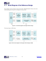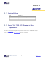
1
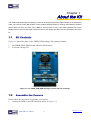
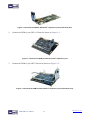
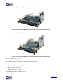
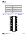
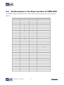
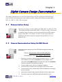
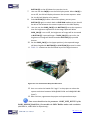
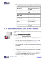
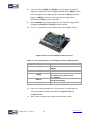
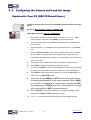
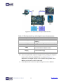
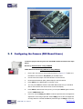
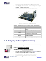
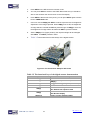
Terasic TRDB_D5M Digital Camera Package Page Index CONTENTS CHAPTER 1 ABOUT THE KIT ................................................................................................................................. 1 1.1 KIT CONTENTS ..................................................................................................................................................... 1 1.2 ASSEMBLE THE CAMERA ...................................................................................................................................... 1 1.3 GETTING HELP ..................................................................................................................................................... 3 CHAPTER 2 TRDB_D5M .......................................................................................................................................... 4 2.1 FEATURES............................................................................................................................................................. 4 2.2 PIN-OUT OF THE 40-PIN CONNECTOR ON TRDB-D5M ....................................................................................... 5 2.3 PIN DESCRIPTION OF THE 40-PIN INTERFACE OF TRDB_D5M .......................................................................... 6 CHAPTER 3 DIGITAL CAMERA DESIGN DEMONSTRATION ......................................................................... 7 3.1 DEMONSTRATION SETUP...................................................................................................................................... 7 3.2 CAMERA DEMONSTRATION SETUP ON DE4 BOARD ........................................................................................... 7 3.3 CAMERA DEMONSTRATION SETUP ON DE2-115 BOARD.................................................................................... 9 3.4 CONFIGURING THE CAMERA AND LOAD THE IMAGE CAPTURED TO YOUR PC (DE2-70 BOARD USERS)........ 11 3.5 CONFIGURING THE CAMERA (DE2 BOARD USERS) .......................................................................................... 13 3.6 CONFIGURING THE CAMERA (DE1 BOARD USERS) .......................................................................................... 14 3.7 BLOCK DIAGRAM OF THE REFERENCE DESIGN ................................................................................................. 16 CHAPTER 4 APPENDIX ......................................................................................................................................... 17 4.1 REVISION HISTORY............................................................................................................................................. 17 4.2 ALWAYS VISIT TRDB_D5M W EBPAGE FOR NEW APPLICATIONS ..................................................................... 17 TRDB-D5M User Manual 2 www.terasic.com July 1, 2014 Chapter 1 About the Kit The TRDB_D5M Kit provides everything you need to develop a 5 Mega Pixel Digital Camera on the Altera DE4 / DE2_115 / DE2-70 / DE2 / DE1 boards. The kit contains hardware design (in Verilog) and software to load the picture taken into a PC and save it as a BMP or JPG file (DE2-70 only). The Getting Started User Guide enables users to exercise the digital camera functions. This chapter provides users key information about the kit. 1.1 Kit Contents Figure 1-1 shows the photo of the TRDB_D5M package. The package includes: 1. 2. The TRDB_D5M (D5M) board with one CMOS sensor. A reference design CD. Figure 1-1 The TRDB_D5M (D5M) Package Content (CD not including) 1.2 Assemble the Camera Please follow the step below to assemble your camera: 1. Connect the D5M to your DE4 board as shown in Figure 1-2. TRDB-D5M User Manual 1 www.terasic.com July 1, 2014 Figure 1-2 Connect the D5M to DE4 board’s expansion port (outermost port). 2. Connect the D5M to your DE2-115 board as shown in Figure 1-3. Figure 1-3 Connect the D5M to DE2-115 board’s expansion port 3. Connect the D5M to your DE2-70 board as shown in Figure 1-4. Figure 1-4 Connect the D5M to DE2-70 board’s expansion port (outermost port). TRDB-D5M User Manual 2 www.terasic.com July 1, 2014 4. Connect the D5M to your DE2 board as shown in Figure 1-5. Figure 1-5 Connect the D5M to DE2 board’s expansion port (outermost port). 5. Connect the D5M to your DE1 board as shown in Figure 1-6. Figure 1-6 Connect the D5M to DE1 board’s expansion port (outermost port). 1.3 Getting Help Here are some places to get help if you encounter any problem: Email to [email protected] Taiwan & China: +886-3-5750-880 Korea : +82-2-512-7661 Japan: +81-428-77-7000 English Support Line: +1-408-512-1336 TRDB-D5M User Manual 3 www.terasic.com July 1, 2014 Chapter 2 TRDB_D5M This chapter will illustrate the technical details users need to know to modify the reference design for their own purpose. 2.1. Features The D5M kit is designed to use the same strict design and layout practices used in high-end consumer products. The feature set is listed below: 1. 2. 3. 4. 5. 6. High frame rate Superior low-light performance Low dark current Global reset release, which starts the exposure of all rows simultaneously Bulb exposure mode, for arbitrary exposure times Snapshot mode to take frames on demand 7. 8. 9. 10. 11. 12. 13. Horizontal and vertical mirror image Column and row skip modes to reduce image size without reducing field-of-view Column and row binning modes to improve image quality when resizing Simple two-wire serial interface Programmable controls: gain, frame rate, frame size, exposure Automatic black level calibration On-chip PLL TRDB-D5M User Manual 4 www.terasic.com July 1, 2014 Key Performance Parameters Parameter Active pixels Pixel size Color filter array Shutter type Maximum data rate/master clock Full resolution Frame rate VGA (640 x 480) ADC resolution Responsivity Pixel dynamic range SNRMAX Power Supply Voltage I/O Value 2,592H x 1,944V 2.2μm x 2.2μm RGB Bayer pattern Global reset release (GRR), Snapshot 96 Mp/s atonly 96 MHz Electronic rolling (ERS) Programmable upshutter to 15 fps Programmable up to 70 fps 12-bit 1.4 V/lux-sec (550nm) 70.1dB 38.1dB 3.3V 1.7V~3.1V Note. For detail specification of D5M, please refer to TRDB-D5M_Hardware specification.PDF 2.2. Pin-out of the 40-pin connector on TRDB-D5M PIXCLK NC D9 D7 D5 NC D3 D1 NC XCLKIN NC STROBE FVAL SCLK VCC33 NC NC NC NC NC 1 3 5 7 9 11 13 15 17 19 21 23 25 27 29 31 33 35 37 39 2 4 6 8 10 12 14 16 18 20 22 24 26 28 30 32 34 36 38 40 D11 D10 D8 D6 D4 GND D2 D0 NC RESETn TRIGGER LVAL SDATA NC GND NC NC NC NC NC Figure 2-1. The pin-out of the 40-pin connector on TRDB_D5M TRDB-D5M User Manual 5 www.terasic.com July 1, 2014 2.3. Pin Description of the 40-pin Interface of TRDB_D5M The TRDB_D5M has a 40-pin connector on the board. The pin description of the 40-pin connector follows: Pin Numbers 1 2 3 4 5 6 7 8 9 10 11 12 13 14 15 16 17 18 19 20 21 22 23 24 25 26 27 28 29 30 31 32 33 34 35 36 37 38 39 40 Name PIXCLK D[11] NC D[10] D[9] D[8] D[7] D[6] D[5] D[4] NC GND D[3] D[2] D[1] D[0] NC NC XCLKIN RESETn NC TRIGGER STROBE LVAL FVAL SDATA SCLK NC VCC33 GND NC NC NC NC NC NC NC NC NC NC TRDB-D5M User Manual Direction Output Output N/A Output Output Output Output Output Output Output N/A N/A Output Output Output Output N/A N/A Input Input N/A Input Output Output Output I/O Input N/A N/A N/A N/A N/A N/A N/A N/A N/A N/A N/A N/A N/A 6 Description Pixel clock. Pixel data Bit 11 Not Connect Pixel data Bit 10 Pixel data Bit 9 Pixel data Bit 8 Pixel data Bit 7 Pixel data Bit 6 Pixel data Bit 5 Pixel data Bit 4 Not Connect Ground Pixel data Bit 3 Pixel data Bit 2 Pixel data Bit 1 Pixel data Bit 0 Not Connect Not Connect External input clock D5M reset Not Connect Snapshot trigger Snapshot strobe Line valid Frame valid Serial data Serial clock Not Connect Power 3.3V Ground Not Connect Not Connect Not Connect Not Connect Not Connect Not Connect Not Connect Not Connect Not Connect Not Connect www.terasic.com July 1, 2014 Chapter 3 Digital Camera Design Demonstration This chapter illustrates how to exercise the digital camera reference design provided with the kit. Users can follow the instructions in this chapter to build a 5 Mega Pixel camera using their DE4 / DE2_115 / DE2-70 / DE2 / DE1 in minutes. 3. 1 Demonstration Setup The image raw data is sent from D5M to the DE4 / DE2_115 /DE2-70 / DE2 / DE1 board. The FPGA on the DE4 / DE2_115 /DE2-70 / DE2 / DE1 board is handling image processing part and converts the data to RGB format to display on the DVI / VGA monitor. For DE2-70, the image captured at SDRAM can be taken at anytime (snapshot) and uploaded to a PC as a BMP/JPG file. 3. 2 Camera Demonstration Setup On DE4 Board Locate the project directory from the CD-ROM included and follow the steps below: Directory: Demonstration / DE4_230/530_D5M_DVI FPGA Bitstream Used: DE4_230/530_ D5M_DVI.sof 1. Ensure the connection is made correctly as shown in Figure 3-1. Make sure the D5M is connected to JP4 (GPIO 1) and DVI daughter card is connected to J20 (HSMC PORT A) of the DE4 board with two THCB-HMF2 interface cards which are bundled in the DE4 kit. 2. Insert the DDR2 memory card into J9 (DDR2 SO-DIMM-1). 3. Connect the DVI TX output of the DVI daughter card to a DVI monitor. 4. Copy the directory DE4_230/530_D5M_VGA from D5M System CD-ROM to the host computer. 5. Download the bitstream (DE4_230/530_D5M_DVI.sof) to the DE4 board. 6. The system enters the FREE RUN mode automatically. Press TRDB-D5M User Manual 7 www.terasic.com July 1, 2014 BUTTON [0] on the DE4 board to reset the circuit. 7. 8. 9. User can use the SW[0] to set the DVI display mode. When SW [0] is set to Off, the DVI will display whatever the camera captures. when On, the DVI will display color pattern. Press BUTTON [2] to take a shot of the photo; you can press BUTTON [3] again to switch back to FREE RUN mode and you should be able to see whatever the camera captures on the VGA display.. User can use the SLIDE_SW [0] with BUTTON [1] to set the exposure time for brightness adjustment of the image captured. When SLIDE_SW [0] is set to Off, the brightness of image will be increased as BUTTON [1] is pressed longer. If SLIDE_SW [0] is set to On, the brightness of image will be decreased as BUTTON [1] is pressed shorter. 10. Set the SLIDE_SW [1] to On (upper position), the captured image will be enlarged with BUTTON [0] and BUTTON [3] pressed in order. 11. Table 3-1 summarizes the functional keys of the digital camera. Figure 3-1 The Connection Setup for DE4 users 12. User can revise the header file "vpg.h" in the project to select the system resolution between SXGA@1280*1024 and VGA@640*480 (note*). 13. After revision, regenerate the project and repeat above steps. Note: users should revise the parameter ‘PORT_SIZE_BYTES’ of the DDR2_ODIMM_Read/Write_Port modules in SOPC Builder under each resolution (640*480*4, 1280*1024*4 respectively) . TRDB-D5M User Manual 8 www.terasic.com July 1, 2014 Table 3-1 The functional keys of the digital camera demonstration Component Function Description BUTTON [0] Reset circuit BUTTON [1] Set the new exposure time (use with SW[0] ) BUTTON [2] Trigger the Image Capture (take a shot) BUTTON [3] Switch to Free Run mode SLIDE_SW [0] SLIDE_SW [1] Off: Extend the exposure time On: Shorten the exposure time On: ZOOM in Off: Normal display On: Color pattern display SW [0] Off: Normal display HEX[1:0] Frame counter (Display the low 8 bits ONLY) 3. 3 Camera Demonstration Setup On DE2-115 Board Locate the project directory from the CD-ROM included and follow the steps below: Directory: Demonstration / DE2_115_CAMERA FPGA Bitstream Used: DE2_115_ CAMERA.sof 1. Ensure the GPIO voltage level is set to 3.3V via JP6 (GPIO_VCCIO) of the DE2-115 board. 2. Ensure the connection is made correctly as shown in Figure 3-2. Make sure the D5M is connected to JP5 (GPIO) of the DE2-115 board. 3. Connect the VGA output of the DE2-115 board to a VGA monitor. 4. Copy the directory DE2_115_D5M_VGA from D5M System CD-ROM to the host computer. 5. Download the bitstream (DE2_115_D5M_VGA.sof/pof) to the DE2_115 board. 6. 7. The system enters the FREE RUN mode automatically. Press KEY[0] on the DE2-115 board to reset the circuit. Press KEY[2] to take a shot of the photo; you can press KEY[3] again to switch back to FREE RUN mode and you should be able to see whatever the camera captures on the VGA display.. TRDB-D5M User Manual 9 www.terasic.com July 1, 2014 8. 9. User can use the SW[0] with KEY[1] to set the exposure time for brightness adjustment of the image captured. When SW[0] is set to Off, the brightness of image will be increased as KEY[1] is pressed longer. If SW[0] is set to On, the brightness of image will be decreased as KEY[1] is pressed shorter. Set the SW[16] to On (upper position), the captured image will be enlarged with KEY[0] and KEY[3] pressed in order. 10. Table 3-2 summarizes the functional keys of the digital camera. Figure 3-2 The Connection Setup for DE2-115 users Table 3-2 The functional keys of the digital camera demonstration Component KEY[0] KEY[1] Function Description Reset circuit Set the new exposure time (use with SW[0] ) Trigger the Image Capture (take a shot) Switch to Free Run mode Off: Extend the exposure time KEY[2] KEY[3] SW[0] On: Shorten the exposure time On: ZOOM in SW[16] Off: Normal display HEX[7:0] Frame counter (Display ONLY) 11. User can revise the header file "VGA_Param.h" in the project to select the system resolution between SVGA@800*600 and VGA@640*480. 12. After revision, regenerate the project and repeat above steps. TRDB-D5M User Manual 10 www.terasic.com July 1, 2014 3. 4 Configuring the Camera and Load the Image Captured to Your PC (DE2-70 Board Users) Locate the project directory from the CD-ROM included and follow the steps below: Directory: Demonstration / DE2_70_CAMERA / SW FPGA Bitstream Used: DE2_70_ CAMERA.sof 1. Ensure the connection is made correctly as shown in Figure 3-3. Make sure the D5M is connected to J5 (GPIO 1) of the DE2-70 board. 2. Copy the directory DE2_70_CAMERA from D5M System CD-ROM to the host computer. 3. Execute the DE2_70_CAMERA.exe form the directory DE2_70_CAMERA / SW. 4. Click the ‘Download Code’ button. (Error message will pop up for warning since the DE2-70 is loaded with factory default image, which cannot be transmitted. Click ‘OK’ button to skip the error message and click ‘Download Code’ to proceed. 5. 6. 7. 8. 9. Connect the VGA output of the DE2-70 board to a VGA monitor. Press KEY0 on the DE2-70 board to reset the circuit. You can press KEY3 to switch to the FREE RUN mode and you should be able to see whatever the camera captures on the VGA display. Press KEY2 to take a shot of the photo; you can press KEY3 again to switch back to FREE RUN mode. Users can use the SW[0] with KEY1 to set the exposure time for brightness adjustment of the image captured. When SW[0] is set to Off, the brightness of image will be increased as KEY1 is pressed longer. If SW[0] is set to On, the brightness of image will be decreased as KEY1 is pressed shorter. 10. Set the SW[16] to On (upper position), the captured image will be enlarged with KEY0 and KEY3 pressed in order. 11. Table 3-3 summarizes the functional keys of the digital camera. TRDB-D5M User Manual 11 www.terasic.com July 1, 2014 Figure 3-3 The Connection Setup for DE2-70 users Table 3-3 The functional keys of the digital camera demonstration Component Function Description KEY[0] KEY[1] Reset circuit Set the new exposure time (use with SW[0] ) Trigger the Image Capture (take a shot) Switch to Free Run mode KEY[2] KEY[3] Off: Extend the exposure time SW[0] On: Shorten the exposure time On: ZOOM in SW[16] Off: Normal display HEX[7:0] Frame counter (Display ONLY) 12. Users can upload the captured image to PC by clicking the ‘Capture’ button of the ‘DE2_70_CAMERA.exe’ as shown in Figure 3-4. Meanwhile, the digital camera is set to photo-taking mode. Press KEY3 to switch back to FREE RUN mode. 13. Click ‘Save’ button to save the captured image as a JPG or BMP file. TRDB-D5M User Manual 12 www.terasic.com July 1, 2014 Figure 3-4 The DE2_70_camera tool 3. 5 Configuring the Camera (DE2 Board Users) Locate the project directory from the CD-ROM included and follow the steps below: Directory: Demonstration / DE2_CAMERA FPGA Bitstream Used: DE2_D5M.sof or DE2_D5M.pof 1. Ensure the connection is set correctly as shown in Figure 3-5. Make sure the D5M is connected to JP2 (GPIO 1) of the DE2 board. 2. Connect the VGA output of the DE2 board to a VGA monitor. 3. Download the bitstream (DE2_D5M.sof/pof) to the DE2 board. 4. Press KEY0 on the DE2 board to reset the circuit. 5. You can press KEY3 to switch to the FREE RUN mode and you should be able to see whatever the camera sees on the VGA display. 6. Press KEY2 to take a shot of the photo; you can press KEY3 again to switch back to FREE RUN mode. 7. Users can use the SW[0] with KEY1 to set the exposure time for brightness adjustment of the image captured. When SW[0] is set to Off, the brightness of image will be increased as KEY1 is pressed longer. If SW[0] is set to On, TRDB-D5M User Manual 13 www.terasic.com July 1, 2014 the brightness of image will be decreased as KEY1 is pressed shorter. 8. Set the SW[16] to On (upper position), the captured image will be enlarged with KEY0 9. and KEY3 pressed in order. Table 3-4 summarizes the functional keys of the digital camera. Figure 3-5 The Connection Setup for DE2 users Table 3-4 The functional keys of the digital camera demonstration Component KEY[0] KEY[1] Function Description Reset circuit Set the new exposure time (use with SW[0] ) Trigger the Image Capture (take a shot) Switch to Free Run mode Off: Extend the exposure time KEY[2] KEY[3] SW[0] On: Shorten the exposure time On: ZOOM in SW[16] Off: Normal display HEX[7:0] Frame counter (Display ONLY) 3. 6 Configuring the Camera (DE1 Board Users) Locate the project directory from the CD-ROM included and follow the steps below: Directory: Demonstration / DE1_CAMERA FPGA Bitstream Used: DE1_D5M.sof or DE1_D5M.pof 1. Ensure the connection is set correctly as shown in Figure 3-6. Make sure the D5M is connected to JP2 (GPIO 1) of the DE1 board. 2. Download the bitstream (DE1_D5M.sof/pof) to the DE1 board. 3. Connect the VGA output of the DE1 board to a VGA monitor. TRDB-D5M User Manual 14 www.terasic.com July 1, 2014 4. Press KEY0 on the DE1 board to reset the circuit. 5. You can press KEY3 to switch to the FREE RUN mode and you should be able to see whatever the camera sees on the VGA display. 6. Press KEY2 to take a shot of the photo; you can press KEY3 again to switch back to FREE RUN mode. 7. Users can use the SW[0] with KEY1 to set the exposure time for brightness adjustment of the image captured. When SW[0] is set to Off, the brightness of image will be increased as KEY1 is pressed longer. If SW[0] is set to On, the brightness of image will be decreased as KEY1 is pressed shorter. 8. Set the SW[8] to On (upper position), the captured image will be enlarged with KEY0 9. and KEY3 pressed in order. Table 3-5 summarizes the functional keys of the digital camera. Figure 3-6 The Connection Setup for DE1 users Table 3-5 The functional keys of the digital camera demonstration Component KEY[0] KEY[1] Function Description Reset circuit Set the new exposure time (use with SW[0] ) Trigger the Image Capture (take a shot) Switch to Free Run mode Off: Extend the exposure time KEY[2] KEY[3] SW[0] On: Shorten the exposure time On: ZOOM in SW[8] Off: Normal display HEX[3:0] TRDB-D5M User Manual Frame counter (Display ONLY) 15 www.terasic.com July 1, 2014 3. 7 Block Diagram of the Reference Design The complete reference design is also located in the CD-ROM attached. Please refer to the following diagram to help you in reading the code provided. Figure 3-7 The block diagram of the digital camera design The below figure for DE4 only. Figure 3-8 The block diagram of the digital camera design for DE4 TRDB-D5M User Manual 16 www.terasic.com July 1, 2014 Chapter 4 Appendix 4. 1 Revision Histor y Date MAR, 24, 2008 AUG, 03, 2009 Change Log Initial Version (Preliminary) AUG, 10, 2010 D5M on DE4 and DE2-115 Board Added revised 4. 2 Always Visit TRDB_D5M Webpage for New Applications We will be continuing providing interesting examples and labs on our TRDB_D5M webpage. Please visit www.altera.com or d5m.terasic.com for more information. TRDB-D5M User Manual 17 www.terasic.com July 1, 2014