1
DataWedge 3.0
Advanced Configuration Guide
DataWedge Advanced Configuration Guide
72E-XXXXXX-01
Rev. 1
December 2008
ii
DataWedge Advanced Configuration Guide
© 2008 by Motorola, Inc. All rights reserved.
No part of this publication may be reproduced or used in any form, or by any electrical or mechanical means,
without permission in writing from Motorola. This includes electronic or mechanical means, such as
photocopying, recording, or information storage and retrieval systems. The material in this manual is subject to
change without notice.
The software is provided strictly on an “as is” basis. All software, including firmware, furnished to the user is on
a licensed basis. Motorola grants to the user a non-transferable and non-exclusive license to use each
software or firmware program delivered hereunder (licensed program). Except as noted below, such license
may not be assigned, sublicensed, or otherwise transferred by the user without prior written consent of
Motorola. No right to copy a licensed program in whole or in part is granted, except as permitted under
copyright law. The user shall not modify, merge, or incorporate any form or portion of a licensed program with
other program material, create a derivative work from a licensed program, or use a licensed program in a
network without written permission from Motorola. The user agrees to maintain Motorola’s copyright notice on
the licensed programs delivered hereunder, and to include the same on any authorized copies it makes, in
whole or in part. The user agrees not to decompile, disassemble, decode, or reverse engineer any licensed
program delivered to the user or any portion thereof.
Motorola reserves the right to make changes to any software or product to improve reliability, function, or
design.
Motorola does not assume any product liability arising out of, or in connection with, the application or use of
any product, circuit, or application described herein.
No license is granted, either expressly or by implication, estoppel, or otherwise under any Motorola, Inc.,
intellectual property rights. An implied license only exists for equipment, circuits, and subsystems contained in
Motorola products.
MOTOROLA and the Stylized M Logo and Symbol and the Symbol logo are registered in the US Patent &
Trademark Office. Bluetooth is a registered trademark of Bluetooth SIG. Microsoft, Windows and ActiveSync
are either registered trademarks or trademarks of Microsoft Corporation. All other product or service names
are the property of their respective owners.
Motorola, Inc.
One Motorola Plaza
Holtsville, New York 11742-1300
http://www.symbol.com
Patents
This product is covered by one or more of the patents listed on the website: www.symbol.com/patents
Warranty
iii
Revision History
Changes to the original manual are listed below:
Change
Rev 1
Date
10/2008
Description
Initial Draft
iv
DataWedge Advanced Configuration Guide
Table of Contents
Patents........................................................................................................................... ii
Warranty ........................................................................................................................ ii
Revision History............................................................................................................. iii
About This Guide
Introduction .................................................................................................................... i
Notational Conventions.................................................................................................. i
Chapter 1: Advanced Configuration Overview
Introduction ...................................................................................................................
Profiles ..........................................................................................................................
Why Profiles ............................................................................................................
Profile0 ....................................................................................................................
Plug-ins ...................................................................................................................
Input Plug-ins ....................................................................................................
Output Plug-ins .................................................................................................
Process Plug-ins ...............................................................................................
Basic Format Process Plug-in ...........................................................................
Data Routes ............................................................................................................
Route Structure of a Profile ...............................................................................
1-1
1-1
1-1
1-2
1-2
1-2
1-3
1-3
1-3
1-4
1-4
Chapter 2: Getting Started
Installation .....................................................................................................................
Installing DataWedge on a PC ......................................................................................
Installing DataWedge on a Mobile Device ....................................................................
Automated Installation ............................................................................................
Manual Installation ..................................................................................................
Using StartUpCtl for Cold/Clean Boot Persistence .................................................
Mass Deployment of DataWedge Configurations .........................................................
Installing without DataWedge Icons ..............................................................................
With Remote Configuration Support .......................................................................
2-1
2-1
2-2
2-2
2-3
2-3
2-3
2-4
2-4
vi
DataWedge Advanced Configuration Guide
Without Configuration Support ................................................................................
Uninstalling DataWedge ...............................................................................................
Remove DataWedge via Host PC ...........................................................................
Remove DataWedge from Mobile Device ...............................................................
Mobile Devices Running Windows Mobile ........................................................
Mobile Devices Running Windows CE ..............................................................
2-4
2-5
2-5
2-6
2-6
2-6
Chapter 3: DataWedge Configuration Mode
Introduction ...................................................................................................................
DataWedge Tray Icon ...................................................................................................
DataWedge Tray Icon Menu .........................................................................................
DataWedge Configuration Modes .................................................................................
Basic Configuration .................................................................................................
Advanced Configuration ..........................................................................................
General Format of User Interface .................................................................................
Launching DataWedge Advanced Configuration ..........................................................
Advanced Configuration Main Menu .......................................................................
3-1
3-1
3-2
3-2
3-2
3-3
3-3
3-4
3-4
Chapter 4: Configuring DataWedge Settings
Settings Menu ...............................................................................................................
Profile Selection ............................................................................................................
Automatic Profile Selection .....................................................................................
Manual Profile Selection .........................................................................................
Setting Manual Profile ...................................................................................................
Manual Profile .........................................................................................................
DataWedge Behaviors ............................................................................................
Configuring DataWedge Log Settings ..........................................................................
Log File Overview ...................................................................................................
Define DataWedge Log Size ...................................................................................
Define Log Backup Folder ......................................................................................
Define Cache Folder ...............................................................................................
Define Log Level .....................................................................................................
4-1
4-2
4-2
4-2
4-3
4-3
4-4
4-5
4-5
4-6
4-6
4-7
4-8
Chapter 5: Managing Profiles
Profiles Menu ................................................................................................................
Creating a Profile ..........................................................................................................
Profile Configuration Menu ...........................................................................................
Enabling/Disabling a Profile ....................................................................................
Deleting a Profile .....................................................................................................
Application Association ...........................................................................................
Adding Applications ..........................................................................................
Associated Application Menu ............................................................................
Selecting a Data Route ...........................................................................................
Define an Input Plug-in for the Data Route .......................................................
Define Output Plug-in for Data Route ...............................................................
Defining Process Plug-ins for Data Route ........................................................
5-1
5-2
5-2
5-3
5-3
5-3
5-4
5-5
5-5
5-7
5-8
5-9
Table of Contents
Chapter 6: Configuring Input Plug-ins
Define Input Plug-in for Profile ......................................................................................
Barcode Scanner Plug-in ........................................................................................
Configuring the Scanner Plug-in ...................................................................................
Enabling/Disabling the Scanner ....................................................................................
Configuring Scanner Decoders .....................................................................................
Configuring Decoders .............................................................................................
Configuring Reader Parameters ...................................................................................
Reader Parameters .................................................................................................
Laser Scanner Reader Parameters ..................................................................
Imager Reader Parameters ..............................................................................
Configuring Scan Parameters .......................................................................................
Scanner Parameters ...............................................................................................
Configuring Interface Parameters .................................................................................
Interface Parameters ..............................................................................................
Input Plug-in Feedback Settings ...................................................................................
Configuring Beeper Feedback Settings ............................................................
Configuring LED Feedback Settings .................................................................
Configuring WAV Feedback Settings ................................................................
Enable/Disable Auto Trigger Mode ...............................................................................
6-1
6-1
6-2
6-3
6-3
6-4
6-5
6-5
6-6
6-8
6-11
6-12
6-12
6-13
6-13
6-14
6-15
6-15
6-16
Chapter 7: Configuring Output Plug-ins
Output Plug-in Selection ...............................................................................................
Keystroke Plug-in Configuration ...................................................................................
Allow Escape Characters ..............................................................................................
Inter Character Delay ....................................................................................................
Configuring Keymap Settings .......................................................................................
Adding a Keymap ....................................................................................................
Modifier Keys ..........................................................................................................
Key Mapping Examples ....................................................................................
Output Plug-in Feedback Settings ................................................................................
Configuring Output Plug-in Feedback Settings .......................................................
7-1
7-2
7-3
7-3
7-4
7-4
7-5
7-5
7-6
7-6
Chapter 8: Configuring Process Plug-ins
Configuring ADF Plug-in ...............................................................................................
Enabling the ADF Process Plug-in ...............................................................................
Specifying Rules to ADF Plug-in ...................................................................................
Configuring ADF Rules ...........................................................................................
Defining Criteria ................................................................................................
Defining Actions ................................................................................................
ADF Supported Actions ....................................................................................
ADF Examples ..................................................................................................
Configuring Basic Format Process Plug-in ...................................................................
Special Characters Supported by Basic format ......................................................
Sticky Keys .............................................................................................................
Basic Format Examples ....................................................................................
8-1
8-2
8-2
8-3
8-3
8-6
8-7
8-8
8-10
8-11
8-11
8-12
vii
viii
DataWedge Advanced Configuration Guide
Chapter 9: DataWedge Remote Configuration
Setting Mobile Device for Remote Configuration .......................................................... 9-1
Configuring through ActiveSync/WMDC ................................................................. 9-1
Configuring over WLAN .......................................................................................... 9-1
Appendix A: Useful Information
Special Scenarios .........................................................................................................
Disabling the Barcode Scanner ..............................................................................
Preventing Data Loss in Remote Desktop ..............................................................
Auto Trigger & Presentation Mode ..........................................................................
Virtual Key Codes .........................................................................................................
ASCII Table ..................................................................................................................
Index
A-1
A-1
A-1
A-2
A-2
A-5
About This Guide
Introduction
DataWedge is a Motorola mobile device application that reads data from input devices and sends it as keystrokes
to consumer applications executing in the foreground on the mobile devices.
DataWedge runs on Motorola mobile devices that operate on Windows CE 5.0 and Windows Mobile 5.0 operating
systems.
This document describes the features and functionality of DataWedge 3 and then goes on to explain how to
configure these features and functionality to interoperate with user applications.
Notational Conventions
The following conventions are used in this document:
• “device” refers to any Motorola enterprise mobility device.
• “User” refers to anyone using an application on the device.
• “You” refers to the End User, System Administrator or Technical Support person using this manual as a
reference to install, configure, operate, maintain and troubleshoot DataWedge.
• Italics are used to highlight the following:
• Chapters and sections in this and related documents
• Dialog box, window and screen names
• Drop-down list and list box names
• Check box and radio button names
• Icons on a screen.
• Bold text is used to highlight the following:
• Key names on a keypad
• Button names on a screen or window.
ii
DataWedge Advanced Configuration Guide
• bullets (•) indicate:
• Action items
• Lists of alternatives
• Lists of required steps that are not necessarily sequential
• Sequential lists (e.g., those that describe step-by-step procedures) appear as numbered lists.
NOTE
This symbol indicates something of special interest or importance to the reader. Failure to read the note
will not result in physical harm to the reader, equipment or data.
CAUTION
WARNING!
This symbol indicates that if this information is ignored, the possiblity of data or material damage may
occur.
This symbol indicates that if this information is ignored the possibility that serious personal
injury may occur.
Chapter 1 Advanced Configuration Overview
Introduction
This chapter provides an overview of components used in DataWedge 3. DataWedge 3 is different from previous
versions of DataWedge in several notable areas which are described in this chapter.
The new version of DataWedge has an architecture based on Profiles (See Profiles) and functionality that is based
on Plug-ins (See Plug-ins). Through the use of plug-ins, the functionality of DataWedge can be modularized into
manageable parts which can be configured to change its functionality according to the foreground application.
The configuration data of DataWedge 3 is stored in XML allowing easy deployment of DataWedge across many
mobile devices with different platforms. A web-based interactive user interface is provided to manipulate that data
and configure DataWedge.
Profiles
A profile contains information on how DataWedge should behave with different applications.
Profile information consists of;
• One or more applications
• One or more data routes (path of the data flow from input plug-in through one or more process plug-ins to an
output plug-in)
• Input plug-in configurations
• Output plug-in configurations
• Process plug-in configurations (ordered set of process plug-ins with their configurations for each data path).
DataWedge has a pre-configured default profile, Profile0 (See Profile0), which is created automatically the first
time DataWedge is run. Apart from Profile0, DataWedge supports user defined profiles.
Why Profiles
Through the use of profiles, each application can have a DataWedge configuration tailored to it. For example, each
user application can have a profile which outputs scanned data in the required format when that application comes
1-2
DataWedge Advanced Configuration Guide
to the foreground. Thus DataWedge can be configured to process the same set of captured data differently based
on the requirements of each application.
The figures above show two applications associated with two individual profiles. These figures show the data as it
appears in each application after scanning the same barcode. The profile which the first application is associated to
has been configured to add the prefix "Start" to the scanned data and the other profile which the second application
is associated with has not been configured to perform data modifications, thus the scanned data remains
unmodified.
Profile0
Profile0 is the generic default profile which is used when there are no user created profiles associated with an
application. It has the barcode scanner plug-in set as the input plug-in and the keystroke plug-in set as the output
plug-in, and includes configuration information for both scanner and keystroke plug-ins.
As the default profile, Profile0 can be edited but cannot be associated with an application. That is, DataWedge
allows manipulation of data routes and the plug-in settings for Profile0 but it does not allow assignment of a
foreground application. This configuration allows DataWedge to send output data to any foreground application
other than applications associated with user-defined profiles when Profile0 is enabled.
Profile0 can be disabled if required. This allows DataWedge to only send output data to those applications which
are associated in user-defined profiles. For example, if Profile0 is disabled, DataWedge is set to auto profile
selection, and there are two user-created profiles associated with two different applications, then DataWedge only
sends data to those applications specified in the user-created profiles. This adds additional security to DataWedge
enabling the sending of data only to specified applications. (See Profile Selection)
Plug-ins
A plug-in is a software module utilized in DataWedge to extend its functionality to encompass technologies such as
Barcode scanning and RFID. The plug-ins can be categorized into three types based on their operations.
• Input plug-ins
• Process plug-ins
• Output plug-ins
Input Plug-ins
An input plug-in supports an input device, such as a barcode scanner contained in, or attached to a Motorola
mobile computer. DataWedge contains base plug-ins for these input devices.
Advanced Configuration Overview
1-3
Barcode Scanner Plug-in
The barcode scanner plug-in is responsible for reading data from the integrated barcode reader. The scanner
plug-in supports different types of barcode readers including laser, imager and camscan (Camera Scan). Raw data
read from the barcode reader can be processed or formatted using process plug-ins (See Process Plug-ins) as
required. DataWedge has built-in feedback functionality for the barcode reader to issue user alerts. The feedback
settings can be configured according to user requirement.
Output Plug-ins
The output plug-in is responsible for dispatching the data read from input plug-ins to a foreground application on
the mobile device.
Keystroke Plug-in
The Keystroke Plug-in is an output plug-in that collects and sends data received from input plug-ins to foreground
applications by emulating keystrokes.
Process Plug-ins
ADF Process Plug-in
The term ADF is an acronym for Advanced Data Formatting. The ADF plug-in applies rules (actions to be
performed based on defined criteria) to the data received from the input plug-in before sending it to the foreground
application through an output plug-in. Received data is processed through a set of ADF rules that can be defined
when configuring DataWedge. For those familiar with the ADF as supported by Motorola Hand Held Scanners, the
ADF plug-in provides equivalent functionality.
Rules
The ADF process plug-in consists of one or more rules. DataWedge formats the output data according to the first
matching rule. A rule is a combination of criteria and a set of actions to be performed, upon fulfillment of the criteria
set in the rule.
Criteria
Criteria can be set according to input plug-in device, symbology, or matching string within the data (at the specified
position and length). Received data must match the defined criteria in order for the data to be processed by the
rule.
Actions
Actions are a set of procedures defined to format data. For example an action can be defined to send the first
number of characters to the output plug-in, pad the data buffer with a character or string, remove spaces in data,
etc.
Basic Format Process Plug-in
The Basic Format (aka Prefix/Suffix) plug-in is similar to the prefix/suffix feature that exists in earlier versions of
DataWedge and it allows DataWedge to add either a predefined prefix or a suffix to the captured data before
passing it to an output plug-in.
The Basic Format process plug-in allows setting a string, sticky keys (See Sticky Key Definitions), virtual keys (See
Virtual Key Codes), control characters (characters sent by pressing Ctrl key) and escape sequences (See Escape
Sequences Supported by DataWedge) at the beginning or at the end of the data received from the input plug-in.
Also this process plug-in can be used to send data in hexadecimal format, append TAB and/or ENTER keys or
restrict sending data.
1-4
DataWedge Advanced Configuration Guide
Data Routes
A data route specifies the path data takes inside DataWedge, starting from an input plug-in, optionally going
through one or more process plug-ins, and ending at an output plug-in. Each route allows one source input plug-in
and one destination output plug-in. When there are many input and output plug-ins, the way in which data flows
from one input plug-in, through any process plug-ins, and finally to an output plug-in can be specified using routes.
Route Structure of a Profile
A profile can have multiple configurations for given process plug-ins depending on the data routes it is associated
with. However, only a single instance of input and output plug-in configuration can be associated with a profile.
For example review the below given scenarios for a newly created profile. In the first instance, the data route of the
profile has;
• Scanner input plug-in
• ADF process plug-in and
• Keystroke output plug-in
In the second data route of the same profile has;
• Scanner input plug-in
• ADF process plug-in
• Basic format process plug-in and
• Keystroke output plug-in
In the first scenario the profile configuration includes a single configuration for scanner input plug-in, single
configuration for keystroke output plug-in, single configuration for ADF process plug-in but in the second scenario,
the data route of the profile has multiple process plug-ins (ADF and Basic format) to facilitate multiple processing
requirements i.e. data is sent to the foreground application in multiple formats.
Chapter 2 Getting Started
Installation
DataWedge can be installed on a mobile device via a PC or by copying the DataWedge.cab file found in
C:\Program Files\Motorola DataWedge\Cab\ to the mobile device and executing it.
The DataWedge installation package is available from the Motorola Product Support site at
http://support.symbol.com/support/product/DEV_SW_TOOLS.html.
Installing DataWedge on a PC
Run the DataWedge installation package on the PC. Follow the instructions provided by the installation wizard to
complete the installation. The following files/folders are installed on the PC.
• Cab\DataWedge.CAB
- DataWedge Cabinet file
• INI\DataWedge.ini
- DataWedge configuration settings file
• DataWedgeInstaller.exe
- Executable program to install DataWedge on a mobile device
• DataWedge Configuration Guide
• Remote Config\
- DataWedge Remote Configuration folder
• Readme.htm
- Quick reference file
• WebUpdates.htm
- DataWedge updates web location
2-2
DataWedge Advanced Configuration Guide
Installing DataWedge on a Mobile Device
Automated Installation
1.
Establish a Microsoft ActiveSync® connection between host PC and mobile device.
2.
On the host PC, go to Start > Programs > Motorola DataWedge > Install DataWedge to initiate the automatic
installation process.
3.
A screen displaying installation details appears on the mobile device.
Figure 2-1 Installation Location Details
Select the preferred install location using the radio button and press Install to proceed with the installation of
DataWedge on the mobile device.
4.
Wait a few moments while DataWedge is installed to the mobile device. After a successful installation, a
message window appears to announce that DataWedge is installed.
Figure 2-2 Successful Installation Notofication
Tap ok to close the message window.
5.
After the installation is completed DataWedge starts automatically.
Getting Started
2-3
Manual Installation
1.
Establish a Microsoft ActiveSync® connection between host PC and the mobile device.
2.
Go to Start Menu > Programs > Motorola DataWedge > Manual Installation and copy DataWedge.CAB to the
mobile computer.
3.
Run DataWedge.CAB on the mobile computer to install DataWedge. Follow the installation procedure to
successfully install DataWedge on the mobile device.
Using StartUpCtl for Cold/Clean Boot Persistence
Using the Motorola StartUpCtl utility, DataWedge can be installed on the mobile device for persistence following
clean/cold boot sequences.
1.
Download the StartUpCtl installation package from Motorola Product Support site at
http://support.symbol.com/support/product/DEV_SW_TOOLS.html.
2.
Install StartUpCtl on the mobile device. Refer to the StartUpCtl User Manual for details on how to install
StartUpCtl on the mobile device.
3.
Create OnRestore_DataWedge.txt file and enter the following command.
\Windows\wceload.exe /noui /delete 0 "\Application\DataWedge.cab"
4.
Copy the OnRestore_DataWedge.txt file to the Application\StartUpCtl\OnRestore folder of the mobile device.
5.
Go to Start Menu > Programs > Motorola DataWedge > Manual Installation and copy DataWedge.CAB to the
\Application folder of the mobile device. The DataWedge.CAB file is copied to the \Application folder, since that
folder has been set as the location for the DataWedge.CAB in the OnRestore_DataWedge.txt file
When the mobile device goes through a clean/cold boot cycle, StartUpCtl automatically reinstalls DataWedge.
Mass Deployment of DataWedge Configurations
Once DataWedge configuration is completed, the settings and profile information can be cloned to other mobile
devices.
NOTE
The configurations done on a mobile device can ONLY be deployed on an identical mobile device (i.e.
same hardware and operating system). Attempting to deploy the same configurations on a different
mobile device may not yield the expected results.
To deploy DataWedge settings on multiple mobile devices copy the \Program Files\DataWedge\Config folder from
the source mobile device (mobile device on which DataWedge was configured) and save that folder in the same
location on the other devices.
Run or restart DataWedge on the cloned mobile devices for the settings to take affect.
2-4
DataWedge Advanced Configuration Guide
Installing without DataWedge Icons
DataWedge can be installed without DataWedge quick launch options such as the tray icon menu or the Start
Menu links on the device side. This alternative method may be required to avoid unauthorized access to
DataWedge configuration settings. Other instances for using this feature can be to centralize a mass configuration
of DataWedge settings via a PC and for making use of a third party application to control and configure
DataWedge. The following methods describe how to install DataWedge without the quick launch options.
With Remote Configuration Support
The following lists step-by-step procedures to install DataWedge without the quick launch options on the mobile
device side and allowing only Remote Configuration (See DataWedge Remote Configuration) to access and
configure DataWedge.
1.
Install DataWedge on the PC
2.
Install DataWedge on the mobile device via ActiveSync.
3.
Install Motorola StartUpCtl utility on the PC.
4.
Install StartUpCtl on the mobile device via ActiveSync
5.
Using ActiveSync navigate to the \Application\StartUpCtl\OnReset folder on the mobile device and copy the
OnReset.txt file to the host PC. Open the OnReset.txt it and add the following two lines.
"\Program Files\DataWedge\DataWedge.exe"
"\Program Files\DataWedge\dwhttpd.exe"
6.
Save and copy the file back to the \Application\StartUpCtl\OnReset folder on the mobile device.
7.
Using ActiveSync navigate to the Windows\StartUp folder on the mobile device and delete the DataWedge
shortcut (DataWedge.lnk).
8.
Delete DataWedge shortcut from the start menu of the mobile device. The location o the shortcut varies
depending of the operating system.
• On Windows Mobile - \Windows\start menu\programs\DataWedge.lnk
• On Windows CE
9.
- \Windows\Programs\DataWedge.lnk
Warm boot the device
NOTE
When DataWedge is installed using this method, the configuration can only be done via the Remote
Configuration option.
Without Configuration Support
1.
Ensure that DataWedge is fully configured.
2.
Follow the same steps described in Method 1 except for the entries made in the OnReset.txt file. Instead of
having both entries, enter only the following in the OnReset.txt file.
"\Program Files\DataWedge\DataWedge.exe"
NOTE
When this method is implemented no DataWedge configuration option is available therefore make sure
that the appropriate configuration is done prior to carrying out the above steps..
Getting Started
2-5
Uninstalling DataWedge
DataWedge can be uninstalled from the mobile device via the host PC or by using the Add/Remove Programs
applet on the mobile device.
Remove DataWedge via Host PC
Method 1
1.
Establish a Microsoft ActiveSync® connection between host PC and the mobile device.
2.
On the host PC, go to Start > Programs > Motorola DataWedge > DataWedge Installer.
3.
When Applications Already Installed prompt appears, select No to move to Add/Remove Programs window.
Figure 2-3 Add/Remove Programs Window
4.
De-select the checkbox alongside Motorola DataWedge and press OK to remove DataWedge.
Method 2
1.
Establish a Microsoft ActiveSync® connection between the mobile device and the host PC.
2.
In the Notification Area of the host PC, right click the ActiveSync icon and select Open Microsoft ActiveSync
option or alternatively, double-click the ActiveSync icon to open the Microsoft ActiveSync window.
3.
In the Microsoft ActiveSync window go to Tools > Add/Remove Programs.
4.
De-select the checkbox alongside Motorola DataWedge and press OK to remove DataWedge
NOTE
Apart from the described methods, DataWedge can be uninstalled from both the host PC and from the
mobile device by highlighting Motorola DataWedge from the list in the Add/Remove Programs window and
pressing the Remove button under Remove from both locations panel. Press OK when the Remove
Application dialog box appears, to confirm removal of DataWedge from the mobile device and the host
PC. This option only removes the temporarily stored CAB file from the host PC and not the DataWedge
program group which includes Readme, DataWedge Configuration Guide etc.
2-6
DataWedge Advanced Configuration Guide
Remove DataWedge from Mobile Device
The method for uninstalling programs from the mobile device side differs slightly according to the operating
system.
Mobile Devices Running Windows Mobile
1.
On a Windows Mobile based mobile device, go to Start Menu > Settings to open the Settings window.
2.
Select the System tab from the Settings screen.
3.
Tap the Remove Programs icon.
4.
Select Motorola DataWedge from the list and tap the Remove button. Tap the Yes button when the Remove
Program dialog appears to uninstall DataWedge from the mobile device.
Mobile Devices Running Windows CE
1.
On a Windows CE based mobile device, go to Start Menu > Settings > Control Panel to open the Control Panel
window.
2.
Tap the Remove Programs icon.
3.
Select Motorola DataWedge from the list of installed programs and tap the Remove button. Tap the Yes button
when the Remove Program dialog appears to uninstall DataWedge from the mobile device.
Chapter 3 DataWedge Configuration Mode
Introduction
DataWedge configuration is handled through a browser based interface. It consists of a hierarchy of menus which
can be navigated using the keypad or the touch-sensitive screen (if present). The DataWedge configuration
settings are saved in XML files.
DataWedge Tray Icon
DataWedge is launched on the mobile device upon successful installation. The tray icon appears on the windows
taskbar to indicate that DataWedge is in operation. Tap on the icon to open the DataWedge tray icon menu.
DataWedge Tray Icon
Figure 3-4 Mobile Device Desktop (DataWedge Icon)
3-2
DataWedge Advanced Configuration Guide
DataWedge Tray Icon Menu
Use the tray icon menu to start/stop DataWedge, to access basic/advanced configuration modes and to terminate
DataWedge activities on the mobile device.
Figure 3-5 DataWedge Tray Icon Menu
• Select Start DataWedge to launch DataWedge on the mobile device.
• Select Stop DataWedge to stop DataWedge on the mobile device. When this option is selected, DataWedge
can be launched again using the tray icon menu.
• Select Advanced Configuration to launch advanced configuration mode.
• Select Basic Configuration to launch basic configuration mode.
• Select Exit to close DataWedge on the mobile device. When this option is selected, DataWedge is shut down
and the tray icon is hidden as well. To start DataWedge again use the Start Menu.
DataWedge Configuration Modes
The DataWedge Configuration is a XML/HTML based interface that can manipulate DataWedge settings. Changes
made through the interface are saved in XML format and can be deployed to other mobile devices that have
DataWedge installed allowing those mobile devices to have the same configuration.
There are two configuration modes are available for DataWedge.
Basic Configuration
For those users who only need the features of a basic ScanWedge, the basic configuration provides a simpler and
quicker interface to a limited number of configuration options similar to that found in ScanWedge and earlier
versions of DataWedge. The basic configuration is a limited view of Profile0, the default profile, configuration
options. Configuration is limited to the Barcode input plug-in, Basic Format process plug-in and Keystroke output
plug-in.
The basic configuration does not provide access to user-created profiles or other settings, nor does it affect any
settings that may have been made through the Advanced configuration.
DataWedge Configuration Mode
3-3
Refer to the DataWedge Basic Configuration Guide for more details.
Advanced Configuration
The advanced configuration allows users to create customized profiles. Use this mode to configure DataWedge to
collect data from different input devices, process the captured data using both ADF and/or Basic Format plug-ins
and send that processed data to different output devices.
In addition to multiple profile support, the advanced configuration mode also allows DataWedge specific settings to
be configured via the Settings menu (See Configuring DataWedge Settings).
NOTE
This document only explains the features and functionality of the advanced configuration mode.
General Format of User Interface
The DataWedge configuration user interface (UI) has a number of elements. Running across the top of the page is
a location bar, which indicates the current location within the menu hierarchy.
Location Bar
Sub menu available
Status
Keyboard Shortcut
Menu item name
description
The menu item list is formatted into four columns. The first is a status column indicating whether the item is
enabled or not, where applicable. The second column gives the keyboard shortcut for that menu item, enabling
navigation of the menu without the need of touch screen input. Column three is the name/description of the menu
item. The fourth column is a sub menu indicator that generally displays ellipses ("…") if a sub menu is available for
that menu item. Access the sub menu by selecting that menu item.
The "0" item is universally used as the shortcut to navigate to the previous page. In the main menu only, the "0"
item is used to exit from the configuration utility.
3-4
DataWedge Advanced Configuration Guide
Launching DataWedge Advanced Configuration
Select Advanced Configuration from the tray icon menu to access the advanced DataWedge configuration.
Advanced Configuration Main Menu
The advanced cnfiguration main menu is displayed on the mobile device screen. This page consists of four menu
items, namely Profiles, Settings, About and Exit.
Figure 3-6 Advanced Configuration Main Menu Page
Use the appropriate keyboard shortcut or the touch screen to navigate through the main menu.
• Select Profiles to open the Profiles menu.
• Select Settings to open the Settings menu.
• Select About to display product information of DataWedge.
• Select Exit to exit from DataWedge advanced configuration mode.
NOTE
Do not press any buttons until configuration menu is fully loaded as it might hamper the loading process.
Chapter 4 Configuring DataWedge Settings
This chapter provides information on how to set the general DataWedge configuration options. The configuration
interface has built-in functionality to modify the general DataWedge settings.
Settings Menu
The Settings menu page is displayed when the Settings option is selected from the main menu. Use the Settings
menu page to configure general DataWedge settings.
Figure 4-7 Settings Menu Page
• Use Profile Selection to select whether profile switching should be automatic or manual (See Profile
Selection for more details).
• Use Manual Profile to select which profile to use when Profile Selection is set to "Manual" (See Setting
Manual Profile for more details).
• Select Log to configure logging options (See Configuring DataWedge Log Settings for more details).
• Select Back to return to the main menu. Whenever exiting from the Settings menu, a dialog box appears
prompting for confirmation on whether or not to save the changes made to the settings. Press OK to save the
changes made.
4-2
DataWedge Advanced Configuration Guide
Profile Selection
Use Profile Selection page to select whether profile switching should be automatic or manual. This setting
enables/disables switching of profiles based on the foreground application on the mobile computer.
Figure 4-8 Profile Selection Page
Automatic Profile Selection
Auto profile selection enables switching between profiles based on the foreground application.
To enable automatic profile selection, select Auto from the Profile Selection menu.
When automatic profile selection is enabled, DataWedge monitors the foreground application in the mobile device
by checking the application name of the foreground application (exe name). When DataWedge detects a change in
the application name, it searches for the profile associated with that application and loads that profile. If an
associated profile cannot be found, Profile0 is used.
The profile must be enabled for DataWedge to load it. i.e. DataWedge only loads profiles that have their status set
to "Enabled".
Manual Profile Selection
Manual profile selection is similar in functionality to the earlier versions of DataWedge. When profile selection is set
to Manual, DataWedge does not switch between profiles automatically, based on the foreground application, and
only uses the profile specified in the Manual Profile page.
To enable manual profile selection, select Manual from the Profile Selection menu.
See Setting Manual Profile for details on selecting a manual profile.
Configuring DataWedge Settings
4-3
Setting Manual Profile
Select the Manual Profile option from the Settings menu to move to Manual Profile page.
Figure 4-9 Manual Profile Selection Page
The manual profile selection page lists all of the available profiles. Select the desired profile name. Make sure that
the profile selected is enabled (See Enabling/Disabling a Profile).
If the profile selection is set to manual and the selected profile is disabled, DataWedge cannot send data to the
foreground application (See DataWedge Behaviors)
Manual Profile
The manual profile is the profile which is used by DataWedge when profile selection mode is set to "Manual". While
in manual mode, DataWedge sends data only to the foreground application associated with the manual profile.
By default, the manual profile is set to Profile0. This setting allows DataWedge to send data to any foreground
application. A user-created profile can be set as the manual profile using the Manual Profile selection page.
4-4
DataWedge Advanced Configuration Guide
DataWedge Behaviors
The table below explains the different behaviors of DataWedge according to the Manual Profile and Profile
Selection settings.
In this example, Profile1 is a user created profile which has App1.exe set as its associated application. Apart from
Profile1, the default profile, Profile0, is also available in DataWedge.
Table 4-1 DataWedge Behaviors
Profile
Selection
Setting
Manual
Profile
Setting
Profile0
State
(Enabled
/Disabled)
User
Created
Profile
(Profile1)
State
(Enabled
/Disabled)
Current
Foreground
Application
DataWedge Behavior
Manual
Profile0
Enabled
Enabled or
Disabled
Any application
DataWedge runs with
Profile0 (the default profile)
configuration
Manual
Profile0
Disabled
Enabled or
Disabled
Any application
DataWedge is idle and
does not send data to the
foreground application
Manual
Profile1
Enabled or
Disabled
Enabled
Any Application
DataWedge runs with
Profile1 configuration
Manual
Profile1
Enabled or
Disabled
Disabled
Any Application
DataWedge is idle and
does not send data to the
foreground application
Auto
Any profile
Enabled or
Disabled
Enabled
App1.exe
DataWedge sends data to
foreground application
(App1.exe)
Auto
Any profile
Enabled or
Disabled
Disabled
App1.exe
DataWedge is idle and
does not send data to the
foreground application.
(App1.exe)
Auto
Any profile
Enabled
Enabled or
Disabled
Any application
except App1.exe
DataWedge runs with
Profile0 configuration
Auto
Any profile
Disabled
Enabled or
Disabled
Any application
except App1.exe
DataWedge is idle and
does not send data to the
foreground application..
Configuring DataWedge Settings
4-5
Configuring DataWedge Log Settings
Log File Overview
DataWedge application has built-in logging capabilities to record errors, warnings, and other diagnostic messages.
These messages are saved to a text file (DWLog.txt).
The log file records the log entries in the following format:
<Time Stamp>:<Message Type>:Message
<Time stamp> is formatted as YYYY/MM/DD hh:mm:ss.
<Message Type> depicts the type of message that is logged. The following message types can be logged.
•
•
•
•
Error
Warning
Message
Data
- an error has occurred
- a warning is issued
- DataWedge system messages, indicating it is performing a task etc.
- data read from input devices and intermediate data modified by process plug-ins
can be logged to the log file.
Sample Log File
$ 2009/09/09 02:49:32
Error
Invalid Configuration XML
Select the Log option from Settings menu to access the Log page.
Figure 4-10 Log Menu Page
There are four configurable settings for the log file.
• Select Log size to set the physical size of the log file.
• Select Backup folder to define a location to save the log file.
• Select Cache folder to define a location in which the temporary log file is written.
• Select Log level to specify the type of information needed to be in the log file.
4-6
DataWedge Advanced Configuration Guide
Define DataWedge Log Size
To set the physical size of the log file, select the Log size option to move to the Log size page.
Figure 4-11 Log Size Page
Select the storage capacity to allocate for the log file. The maximum allowed size for the log file is 1 MB.
NOTE
If the log file exceeds the set size, DataWedge backs up the text file (DWLog.bak) and creates a new log
file (DWLog.txt) to save the new log entries. However, DataWedge creates only one back up file and the
previously created backup file is replaced by the new back up file.
Define Log Backup Folder
The Backup folder specifies the location where DataWedge saves the log file upon exit or upon being stopped.
Select Backup folder from the Log menu page to move to the Backup folder page.
Figure 4-12 Log Path Page
Using the mobile device keypad and/or the onscreen keyboard, enter the backup folder for the log file, and then
press Save to save.
Configuring DataWedge Settings
4-7
DataWedge writes the log file to the folder specified upon exit or upon being stopped.
Define Cache Folder
The Cache folder specifies a location where the DataWedge log file is written to whilst DataWedge is running.
Windows Mobile makes use of persistent (flash) storage for most of its folders. Writing to persistent (flash) storage
can be slow, so DataWedge allows the use of non-persistent (RAM) storage to speed up the logging process.
Select Cache folder from the Log menu page to move to the Cache folder page.
Figure 4-13 Log Temp Path Page
Use the mobile device keypad and/or the onscreen keyboard to enter the location for the temporary log file, and
then press Save.
By default the cache folder is set to \Temp. For many Motorola devices this default setting is acceptable. An
alternative for Windows Mobile devices is \Cache Disk.
4-8
DataWedge Advanced Configuration Guide
Define Log Level
Select the Log level option from the Log menu to move to the Log level page.
The Log level specifies the level of detail that is logged. Log events up to the given level are written to the log file.
Figure 4-14 Log Level Page
Use the menu to set the log level.
• Select Errors to log only error messages.
• Select Warnings to log error and warning messages.
• Select Messages to log errors, warnings and messages.
• Select Data to log errors, warnings, messages and data in the log file.
Chapter 5 Managing Profiles
This chapter describes how to add and remove profiles and also provides a screen-by-screen tutorial of how to
associate applications to the profiles.
From the DataWedge main menu page, select Profiles to access the Profile menu.
Profiles Menu
The Profiles menu is displayed when Profiles is selected from the main menu.
Figure 5-15 Profiles Menu Page
The Profiles menu page lists all the profiles used in DataWedge. Use this menu to access each profile
configuration.
• Select Profile0 to move to configure Profile0 (the default profile).
• Select Add new to add a new profile.
• Select Back to move to the previous page.
5-2
DataWedge Advanced Configuration Guide
Creating a Profile
From the Profiles menu select the Add new option to create a new profile. DataWedge configuration moves to a
profile name entry form and automatically suggests a unique profile name.
Figure 5-16 Profile Name Entry Form
Using either the device keypad or the onscreen keyboard, press Save to accept the suggested profile name, or
enter a preferred name for the new profile and press Save.
NOTE
Use only alphabetical characters and integers when defining a name for a profile.
When a new profile is created, DataWedge automatically assigns default settings to that profile. The new profile is
added to the list of profiles. To configure the new profile select it from the profile list.
Profile Configuration Menu
Newly created profiles can be customized to suit user requirements.
Figure 5-17 User Defined Profile Menu Page
Managing Profiles
5-3
By default, the new profile is enabled upon its creation.
• Select Enabled to enable/disable the profile
• Select Applications to associate an application to the profile.
• Select Input to configure an input plug-in for the profile.
• Select Output to configure an output plug-in for the profile.
• Select Routes to configure the routes for the profile.
• Select Rename to change the name of the profile.
• Select Delete to remove the profile.
• Select Back to exit the profile configuration. DataWedge prompts for confirmation to save the changes made
to the profile. Select OK to save the changes made to the profile. Select Cancel to discard the changes
made to the profile.
NOTE
When exiting from the profile configuration menu, DataWedge saves the configuration information.
Therefore, to save the changes made to a profile, select OK at the prompt when exiting from that profile.
Enabling/Disabling a Profile
To enable a profile, select Enabled from the profile configuration menu. When the profile is enabled, a tick (3) is
displayed alongside Enabled. If Enabled is selected while the profile is enabled, DataWedge disables that profile.
Deleting a Profile
To delete a profile, select the Delete option from the profile menu. The system requires confirmation for removal of
a profile. Select OK to delete the profile. Select Cancel to abort the operation.
Application Association
Several applications can be associated to a profile. DataWedge sends the output data to whichever of these
applications is in foreground.
When profile selection is set to "Auto", DataWedge loads the profile associated with the current foreground
application and sends data to it using the selected output plug-in. (See Setting Manual Profile for more details)
5-4
DataWedge Advanced Configuration Guide
Select the Applications option on the Profile menu to move to Applications page.
Figure 5-18 Application Association Page
The Applications page lists applications associated to the selected profile. Use this page to associate applications.
Adding Applications
Select the Add new option from the Applications page to move to the page where an application can be added to a
profile.
Figure 5-19 Application Name Entry Form
Use the mobile device keypad or the onscreen keyboard to enter the name of the application in the field and press
Save to add it to the profile. The associated applications are displayed in the Applications menu of the profile.
Managing Profiles
5-5
Associated Application Menu
Select an application from the Applications menu to edit or remove that application.
Figure 5-20 Associated Application Menu
Use this menu page to edit/remove the associated application.
• Select Edit to edit the application name. Using this option, it is possible to associate a different application
(.exe) to the profile. The earlier set application is removed from the selected profile when a different name is
saved.
• Select Delete to remove the application from the profile. At this point DataWedge configuration UI prompts
the user for confirmation to delete the associated application from the profile. Select OK to confirm. Select
Cancel to abort the deletion process.
Selecting a Data Route
Select Routes from the profile main menu to move to the page listing all available data routes.
Figure 5-21 Data Routing List
• Use Route0 menu item to access the default data route between the input, process and output plug-ins.
5-6
DataWedge Advanced Configuration Guide
• Select Add new to add a new data route to the selected profile. A form appears containing a automatically
generated unique name for the new route. Press Save to accept the name or change the name as desired,
then press Save to create the new route.
As new routes are added, they are listed on this page. To configure a route, select the route from the list.
Data Route Configuration
Select a route from the data routes list to configure.
Figure 5-22 Data Route Configuration Main Menu
• Select Enabled to Enable/disable the use of data route. When enabled, a tick (3) is displayed alongside
Enabled. To disable, select Enable again to toggle the Enabled state.
• Select Input to move to a page where an input plug-in for the data route can be selected.
• Select Process to move to a page where the process plug-ins for the data route can be enabled and
configured.
• Select Output to move to a page where an output plug-in for the data route can be selected.
• Select Rename to rename the data route.
• Select Delete to delete the data route.
Managing Profiles
5-7
Define an Input Plug-in for the Data Route
Select Input from the route configuration menu to set an input plug-in to the data route.
Figure 5-23 Input Plug-in for Data Route
This page displayed the current input plug-in associated with the selected data route. Select Plugin to move to a
page listing the available input plug-ins.
Figure 5-24 Input Plug-ins List
Select the desired input plug-in for the route from this page.
NOTE
Input plug-in configuration is done at the profile level; no additional configuration is available at this level.
See Configuring Input Plug-ins for details.
5-8
DataWedge Advanced Configuration Guide
Define Output Plug-in for Data Route
Select the Output option from the route configuration menu to view the output plug-in associated with the selected
data route.
Figure 5-25 Output Plug-in for Data Route
Select Plugin to move to the list of available output plug-ins.
Figure 5-26 Output Plug-ins List
Select the desired output plug-in for the data route from the list.
NOTE
The output plug-in configuration is done at the profile level. Therefore no additional configuration is
available at this level. See Configuring Output Plug-ins for details.
Managing Profiles
5-9
Defining Process Plug-ins for Data Route
Select Process from the route configuration menu to move to the page where available process plug-ins are listed.
Figure 5-27 Process Plug-ins Selection Page
• Select Advanced (ADF) to enable and configure the Advanced Data Formatting (ADF) process plug-in for the
data route.
• Select Basic format to enable and configure the Basic formatting process plug-in for the data route.
5 - 10 DataWedge Advanced Configuration Guide
Chapter 6 Configuring Input Plug-ins
This chapter describes how to configure the input plug-in of a profile. DataWedge uses the input plug-in to access
the selected input device (e.g. barcode scanner) and retrieve the data from it for processing.
Define Input Plug-in for Profile
Select Input from the profile menu to move to the Input plug-in selection page where all available input plug-ins are
listed.
Figure 6-1 Input Plug-in Selection Page
Use the menu on this page for defining an input plug-in for the selected profile. DataWedge ships with one input
plug-in which provides barcode scanning. As additional plug-ins are added, they appear in this list.
Select Barcode to start configuring the barcode input plug-in.
Barcode Scanner Plug-in
The Barcode Scanner plug-in reads the captured data from barcode scanners and queues the data for processing.
6-2
DataWedge Advanced Configuration Guide
Configuring the Scanner Plug-in
When Barcode is selected, DataWedge configuration moves to the page where available scanners are listed.
Figure 6-2 Scanner Selection Page
Select a scanner from this list and move to the plug-in configuration page where all configurable options for that
scanner are listed.
Figure 6-3 Scanner Plug-in Configuration Page
Following is a brief description of the menu items on the scanner plug-in configuration page.
• Select Enabled to enable/disable the scanner.
• Select Decoders to access the supported decoders for the scanner.
• Select Reader Params to access the reader parameters for the scanner. (See Reader Parameters)
• Select Scan Params to access the scanner parameters for the scanner. (See Scanner Parameters)
• Select Interface Params to access the interface parameters for the scanners. (See Interface Parameters)
• Select Feedback to configure the notification options for the scanner. (See Input Plug-in Feedback Settings)
Configuring Input Plug-ins
6-3
• Select Auto trigger to enable/disable auto trigger mode for the scanner. When enabled, the scanner
continuously reads barcodes. Use this feature for Motorola Micro Kiosks, such as the MK500. (See
Enable/Disable Auto Trigger Mode)
NOTE
Use of this feature on a battery powered mobile device is not recommended because it can cause the
battery to discharge more rapidly.
Enabling/Disabling the Scanner
Select Enable to enable the scanner. When the scanner is enabled, a tick (3) is displayed alongside the Enabled
item. To disable, select Enable again to toggle the Enabled state.
Configuring Scanner Decoders
Before using the scanner to capture data ensure that the required symbologies are enabled. Select the Decoders
option from the scanner configuration menu to move to the page listing all decoders supported by the scanner.
Figure 6-4 Decoders List
This menu page lists all the decoders supported by the scanner. Use the More option to navigate through the list to
configure additional decoders.
• Select Enable All to enable all decoders for the selected barcode scanner.
• Select Disable All to disable all the decoders.
6-4
DataWedge Advanced Configuration Guide
Configuring Decoders
Select the decoder name from the list, to navigate to the page containing the configurable parameters for that
particular decoder.
Example - Configuring EAN8 Decoder
Select EAN8 from the list to move to the EAN8 decoder configuration page.
Figure 6-5 EAN8 Decoder Page
The Enabled option changes the enable/disable status of the EAN8 decoder. When enabled the scanner allows
reading of EAN8 barcodes.
Select Params to configure additional parameters of the EAN8 decoder.
Figure 6-6 EAN8 Params Page
Use the Convert to EAN13 option to enable/disable conversion of EAN8 barcodes to EAN13 barcodes. A tick (3)
is displayed when this option is enabled.
Configuring Input Plug-ins
Configuring Reader Parameters
Select Reader Params from the scanner configuration menu to configure reader specific parameters.
Figure 6-7 Reader Parameters Page
Reader Parameters
The Reader Parameters settings differ depending on the barcode reader type. See Laser Scanner Reader
Parameters and Imager Reader Parameters for details.
6-5
6-6
DataWedge Advanced Configuration Guide
Laser Scanner Reader Parameters
Table 6-1 Laser Scanner Reader Parameters
Reader
Parameters
Laser Values
Description
Reader Type
Laser
Laser type scan engine is used.
Aim type
Trigger mode:
On/off controlled by the trigger.
Trigger Hold mode:
Trigger can be released but it remains active for the
specified period of time.
Timed Release mode:
Activation stops after a specified period of time, even if the
trigger is held.
Aim duration
0 - 60,000 ms
Sets the amount of time (0 - 60,000 ms in increments of
100 ms).
Aim mode
Dot, Slab, Reticle, None
Describes the aiming modes to use
Dot – Projects a dot used for aiming
Slab – Projects a line used for aiming
Reticle – Projects an aiming pattern used for framing a
barcode.
None – set to none to disable this
Narrow beam
Enable, Disable
Sets the scan beam width to normal or narrow.
Enable – Enable narrow beam
Disable – Disable narrow beam (enable normal beam)
Raster mode
Smart
Creates a single scan line which opens vertically for
PDF417 symbols using the Smart Raster feature. This
feature auto detects the type of bar code presented and
adjusts its pattern accordingly. This provides optimal
performance on 1D, PDF417, and EAN/UCC.
Cyclone
A scan pattern which decodes 1D symbologies in any
orientation.
None
Raster mode disabled.
Open Always
Opens the laser to a full sized raster pattern. Decodes 1D
and PDF417.
NOTE
Raster Mode is not supported on all devices.
Beam timer
0 - 60,000 ms
Sets the maximum amount of time that the laser remains
on (0 - 60,000 ms in increments of 100 ms). A value of 0
sets the laser to stay on.
Control scan LED
Enable, Disable
Not supported, do not modify default setting.
Scan LED logic level
Enable, Disable
Not supported, do not modify default setting.
Klasse Eins enable
Enable, Disable
Not supported, do not modify default setting.
Bidir. redundancy
Enable, Disable
Sets the read direction for the bar code redundancy.
Bidirectional reads in both directions.
Configuring Input Plug-ins
6-7
Table 6-1 Laser Scanner Reader Parameters
Reader
Parameters
Linear security level
Linear Sec (Laser
only)
Laser Values
Description
Sets the number of times a bar code is re-read to confirm
an accurate decode.
All twice:
All twice: Two times read redundancy for all bar codes.
All thrice:
All thrice: Three times read redundancy for all bar codes.
Long and Short:
Long and Short: Two times read redundancy for long bar
codes, three times for short bar codes.
Redundancy + length:
Redundancy + length: Two times read redundancy based
on redundancy flags and code length.
Short or Codabar
Short or Codabar: Two times read redundancy if short bar
code or CODABAR.
Pointer timer
0 - 60,000 ms
Sets the maximum amount of time that the pointer
remains on (0 - 60,000 ms in increments of 100 ms). A
value of 0 sets the pointer to stay on.
Raster height
0-100 in.
Sets the Raster Height from 0 to 100 inches in increments
of 5 in. Raster Height is not supported on all devices.
DBP Mode
Describes what type of Digital Bar Pulse (DBP) is being
produced by the scan engine.
Normal
Normal – tells the engine to produce normal DBP.
Composite
Composite – tells the engine to produce composite DBP,
which is 2 different sets of DBP data multiplexed together
for better decode performance.
Note: If the device does not support I2C or if using an
older engine the default value for DBP Mode is Normal. An
attempt to change this mode to Composite results in an
E_SCN_NOTSUPPORTED error.
6-8
DataWedge Advanced Configuration Guide
Imager Reader Parameters
Table 6-2 Imager Reader Parameters
Reader
Parameters
Imager Values
Description
Reader Type
Imager
Imager type engine is used.
Aim type
Trigger mode:
On/off controlled by the trigger.
Timed hold mode:
Trigger can be released but it remains active for the
specified period of time.
Timed Release mode:
Activation stops after a specified period of time, even if the
trigger is held.
Presentation
Special mode enables scanning when motion is detected
in front of the imager. (Currently only supported by
MK500)
Aim duration
0 - 60,000 ms
Sets the amount of time (0 - 60,000 ms in increments
of100 ms).
Aim mode
Dot, Slab, Reticle, None
Describes the aiming modes to use
Dot – Projects a dot used for aiming
Slab – Projects a line used for aiming
Reticle – Projects an aiming pattern used for framing a
barcode.
None – set to none to disable this
NOTE
Both Dot and Slab options are invalid for imager, thus if
selected the setting is overridden to reticle mode.
Beam timer
0 - 60,000 ms
Sets the maximum amount of time that the laser remains
on (0 - 60,000 ms in increments of 100 ms). A value of 0
sets the laser to stay on.
Pointer timer
0 - 60,000 ms
Sets the maximum amount of time that the Pointer Timer
remains on (0 - 60,000 ms in increments of 100 ms). A
value of 0 sets the Pointer Timer to stay on.
NOTE
Img capt. timeout
0 - 60,000 ms
Sets the maximum amount of time for the Image Capture
Timeout (0 - 60,000 ms in increments of 100 ms). A value
of 0 sets the Image Capture Timeout to stay on.
NOTE
Img comp. timeout
0 - 60,000 ms
This parameter is not supported on all devices.
This parameter is not supported on all devices.
Sets the maximum amount of time for the Image
Compress Timeout (0 - 60,000 ms in increments of 100
ms).
NOTE
Image Compress Timeout is not supported on all
devices.
Configuring Input Plug-ins
6-9
Table 6-2 Imager Reader Parameters
Reader
Parameters
Imager Values
Linear security
Description
Sets the number of times a bar code is read to confirm an
accurate decode.
All twice:
All twice: Two times read redundancy for all bar codes.
All thrice:
All thrice: Three times read redundancy for all bar codes.
Long and Short:
Long and Short: Two times read redundancy for long bar
codes, three times for short bar codes.
Short or Codabar
Short or Codabar: Two times read redundancy if short bar
code or CODABAR.
Focus mode
Fixed, Auto
Fixed mode is the only supported focus mode.
Focus position
Far, Near
Specifies the Fixed setting, focus position for Far is 9
inches and focus position for Near is 5 inches.
Poor quality mode
Enable, Disable
This parameter allows poor quality 1D bar codes to be
read, BUT adversely affecting the overall decoding
performance.
Enable – Enables poor quality decoding for 1D barcodes.
Disable – Disables poor quality decoding for 1D barcodes.
Picklist mode
Disabled, Enabled/HW reticule,
Software reticule
This parameter allows the imager to decode only the bar
code that is directly under the cross-hair/reticule (+) part of
the AIM pattern. This feature is most useful in applications
where multiple bar codes may appear in the field of view
during a decode session and only one of them is targeted
for decode. When enabled, bPicklistMode overrides
dwAimMode if no aiming is chosen and use the
AIM_MODE_RETICLE mode. When enabled,
bPicklistMode may adversely affect overall decoding
performance.
Disabled – Disables picklist mode, so any bar code within
the field of view can be decoded.
Enable/HW reticule – Enables picklist mode, so only the
bar code under the cross-hair can be decoded.
Software reticule - Enables picklist mode, so only the bar
code under the cross-hair can be decoded. In this mode
the reticule is seen on the viewfinder as oppose to on the
barcode surface. Especially used with Camera Scan.
6 - 10 DataWedge Advanced Configuration Guide
Table 6-2 Imager Reader Parameters
Reader
Parameters
DPM Mode
Imager Values
Enable, Disable
Description
This parameter allows Direct Part Marking (DPM) bar
codes to be read but may adversely affect overall
decoding performance. DPM is a way of stamping bar
codes directly on physical objects.
Support for this feature is available on DPM enabled
mobile computers only. If this feature is not available and
user attempts to enable it, an error
(E_SCN_NOTSUPPORTED) results.
Enable – Enables decoding of DPM bar codes.
Disabled – Disables decoding of DPM bar codes.
NOTE
This feature cannot be turned on in conjunction with
Picklist as both these modes are mutually exclusive. An
attempt to turn on both results in an error
(E_SCN_NOTSUPPORTED).
Illumination mode
Auto, Always off, Always On
Illumination modes to use.
Possible values are:
Auto Illumination – In this mode the auto-exposure
algorithms decides whether illumination is required or not.
Always on – In this mode external illumination is always
on.
Always off – In this mode external illumination is always
off.
VF left pos.
0 – 600
This setting displays the top left X coordinate of the
viewfinder window.
VF top pos.
0 – 800
This setting displays the top left Y coordinate of the
viewfinder window.
VF right pos.
0 – 600
This setting displays the bottom right X coordinate of the
viewfinder window.
VF bottom pos.
0 – 800
This setting displays the bottom right Y coordinate of the
viewfinder window.
VF mode
Disabled,
This setting displays the Viewfinder modes supported for
scanning. Possible values are:
Enabled,
Static reticule, Dynamic reticule Disable - Viewfinder is not displayed during aiming and
scanning.
Enabled - Only Viewfinder is enabled.
Static Reticule - Displays the Viewfinder as well as draws
a red reticule in the center of the screen which helps
tracking the barcode.
Dynamic Reticule - Displays the Viewfinder as well as
draws a red reticule in the center of the image. If the
barcode in the image is 'decodable' the reticule turns
green to indicate this.
Configuring Input Plug-ins 6 - 11
Table 6-2 Imager Reader Parameters
Reader
Parameters
Imager Values
Description
VF feedback
Disabled, Enabled,
Reticule
This parameter allows selection of the different feedback
parameters on a successful decode. Possible values are:
Disabled - This mode disables any visual feedback on a
successful decode.
Enabled - This mode displays the last image that
successfully decoded. The duration for which the image is
displayed can be set by the Viewfinder feedback time.
Reticule - This mode displays the last image that
successfully decoded and also draws a reticule in the
center of the image.
VF feedback time
0 - 60,000 ms
This displays the Time for which the visual display
selected by Viewfinder feedback mode.
For more information Please refer Motorola Enterprise
Mobility Developer Kit for C Help.
Inverse 1d Mode
Disabled, Enabled, Auto
This parameter allows the user to select decoding on
inverse 1D barcodes.
Disabled - Disables decoding of inverse 1D symbologies.
Enabled - Enables decoding of only inverse 1D
symbologies.
Auto - Allows decoding of both positive as well as inverse
1D symbologies.
Configuring Scan Parameters
Select Scan Params to configure the scan parameters.
Figure 6-8 Scanner Parameter Configuration Page
Use this menu to access and configure the scan parameters.
• Select CodeID to specify the CodeID.
6 - 12 DataWedge Advanced Configuration Guide
• Select Scan Type to specify the type of Code ID to be reported.
See Scan Parameters for more details.
Scanner Parameters
Below table lists all the scan parameters.
Table 6-3 Scan Parameters
Scan Parameters
Code ID Type
Scan Type
NOTE
Values
Description
None
Default setting. No prefix
Symbol
A Symbol defined single character prefix.
AIM
A standard based three character prefix.
Foreground
Foreground reads combine only with other foreground
reads and preempt background reads.
Background
The scan takes place in the background, but only if no
foreground reads are pending.
Monitor
No scanning is requested, but if scanning is initiated by
another application, a monitor read receives a copy (if the
code type is appropriate).
By default, the Scan Type is set to 'Background'. This allows DataWedge to share the scanner with other
scan enabled applications. Setting this parameter to 'Foreground' is not recommended as this may
interfere with other scan enabled applications or vice versa.
Configuring Interface Parameters
Select Interface Params from the scanner configuration menu to set the interface parameters.
Figure 6-9 Interface Parameter Page
Configuring Input Plug-ins 6 - 13
Select a parameter from the list to modify the default value assigned to it.
See Interface Parameters for more details.
Interface Parameters
Table 6-4 Interface Parameters
Interface Parameter
Values
Interface Type
Lighthouse, Camscan
Power Settle Time
0 - 100 ms
Enable Settle Time
0 - 100 ms
Low Power Time
0 - 60,000 ms
Input Plug-in Feedback Settings
Select the Feedback option from the scanner configuration menu to navigate to the feedback settings page where
the feedback parameters can be configured.
Figure 6-10 Feedback Selection Page
Use DataWedge configuration pages to configure the feedback settings for the selected input plug-in.
The scanner plug-in has two events which feedback settings need to be configured.
• Select Good Decode to configure feedback settings for a successful decode.
• Select Bad Decode to configure feedback settings for a unsuccessful decode.
6 - 14 DataWedge Advanced Configuration Guide
Select either Good or Bad decode from the list to move to the corresponding page where the feedback options are
listed.
Figure 6-11 Feedback Module Selection Page
Select a feedback option from the list to configure it. DataWedge uses the beeper, LED or Wav feedback module
for providing user alerts.
• Select the Beeper option to access and configure Beeper feedback.
• Select the LED option to access and configure LED feedback.
• Select the WaveFile option to access and configure Wave File feedback.
Configuring Beeper Feedback Settings
Select Beeper to configure beeper feedback settings.
Figure 6-12 Beeper Configuration Page
• Select Enabled option to enable or disable the beeper feedback. When enabled, a tick (3) is displayed
alongside the Enabled item. To disable, select Enable again to toggle the Enabled state.
• Select Beep frequency option to set the Beep frequency. A form appears allowing the beep frequency to be
changed. Enter the desired value and press Save to save.
Configuring Input Plug-ins 6 - 15
• Select Beep time option to set the beep duration. A form appears allowing the beep duration to be changed.
Enter the desired time (in milliseconds) and press Save to save.
Configuring LED Feedback Settings
Select LED to configure the LED feedback settings.
Figure 6-13 LED Configuration Page
• Select Enabled option to enable or disable the LED feedback.
• Select LED time option to set the LED time. Enter the time duration (in milliseconds) in the form that appears
and press Save to save.
Configuring WAV Feedback Settings
Select WaveFile to configure WAV feedback setting.
Figure 6-14 Wave File Configuration Page
Select Enabled option to enable or disable the WaveFile feedback.
Select .wav file option to specify the WAV file to be used. Enter the path\filename of the .wav file in the form that
appears and press Save to save.
6 - 16 DataWedge Advanced Configuration Guide
Enable/Disable Auto Trigger Mode
From the barcode plug-in configuration main menu, select Auto trigger to enable auto trigger mode for the scanner.
When this feature is enabled, the scanner is activated when movement is detected beneath it and automatically
scans barcodes. Use this feature for Motorola Micro Kiosks, such as the MK500.
NOTE
Use of this feature on a battery powered mobile device is not recommended because it can cause the
battery to discharge more rapidly
By default this feature is disabled on DataWedge. When enabled a tick (3) is displayed alongside Auto trigger
menu item. To disable, select the menu item again to toggle the state.
NOTE
Use of this feature with the camera is not recommended because the Viewfinder is given precedence over
the other foreground applications and therefore, DataWedge configuration interface can be obscured. Use
the DataWedge Remote Configuration to change DataWedge settings whilst in this mode.
Chapter 7 Configuring Output Plug-ins
This chapter describes how to configure the output plug-in of a profile. DataWedge uses the output plug-in to send
captured data to the foreground application.
Screen-by-screen details on output plug-in configuration and the parameters associated with the output plug-in are
described.
Output Plug-in Selection
Select Output from the profile menu to move to the output plug-in list page.
Figure 7-15 Output Plug-in Main Page
Use the menu on this page for selecting an output plug-in. DataWedge ships with one output plug-in which
provides output in the form of keystrokes. As additional plug-ins are added, the plug-in names are displayed in this
list.
7-2
DataWedge Advanced Configuration Guide
Keystroke Plug-in Configuration
Select Keystroke to move to Keystroke configuration main menu page.
Figure 7-16 Keystroke Plug-in Configuration Page
• Select Send as events to enable sending keystrokes as keyboard events. When enabled, a tick (3) is
displayed alongside Send as events menu item. To disable this feature, select the menu item again to toggle
the state. When disabled, Keystrokes are sent to the foreground application as messages.
• Select Allow Escape chars to enable DataWedge to recognise escape sequences in the incoming data and
convert them to keystrokes. A tick (3) is displayed alongside the menu item when this feature is enabled. To
disable this feature, select the menu item again. When disabled, escape sequences are sent as data.
• Select InterChar delay option to specify the delay to be inserted between each keystroke that is sent.
• Select Keymap to specify the keymap settings.
• Select Feedback to specify the feedback settings for events handled by the output plug-in.
This page is the entry point to the keystroke output plug-in configuration. When moving back to the previous page
a dialog box is displayed, prompting confirmation to save any changes made to the keystroke output plug-in. Press
OK to save changes. Press Cancel to revoke any changes.
Configuring Output Plug-ins
7-3
Allow Escape Characters
The Allow Escape chars option configures the Keystroke plug-in to recognize escape sequences in the incoming
data buffer. When this option is enabled DataWedge can process the escape characters in an incoming data
stream and also send escape characters to the foreground application via the Keystroke plug-in. Disabling this
option causes DataWedge to leave escape characters unchanged. For example if a barcode contains characters
"\r" and if Allow Escape chars is enabled, then DataWedge replaces the "\r" with a carriage return character.
However, if Allow Escape chars property is disabled DataWedge treats the "\r" as regular characters, leaving them
unchanged. The above scenario is also true for data modifications done via Basic format process plug-in.
Table 7-5 Escape Sequences Supported by DataWedge
Escape Sequence
Description
\b
Backspace
\f
Form feed
\n
New line
\r
Carriage return
\S
Sticky key
\t
Horizontal tab
\u hhhh
Unicode character in hexadecimal notation.
\v hh
Virtual key represented in hexadecimal notation
\x hh
ASCII character in hexadecimal notation
Inter Character Delay
The inter character delay is the delay (in milliseconds) that is inserted between the keystrokes that are sent.
Select the InterChar delay option to move to a dialog where the inter character delay can be specified.
Use the mobile device keypad or the onscreen keyboard to enter the inter character delay and press Save to save.
7-4
DataWedge Advanced Configuration Guide
Configuring Keymap Settings
The keymap configuration is used to translate characters from the incoming data to alternative characters before
sending to the foreground application.
Select Keymap to move to keymap configurations page.
Figure 7-17 Keymap Configuration Page
Adding a Keymap
Select Add new to add a new key-mapping. A new option titled Mapping is added to the keymap configuration
page.
Select the Mapping option to configure the new keymap.
Figure 7-18 Key Mapping Main Page
• Select Character code to specify the ASCII value of the incoming character.
• Select Key code to specify the virtual key value of the alternate character.
• Select Delete to delete the selected key mapping.
Configuring Output Plug-ins
7-5
Modifier Keys
Modifier keys are special keys that modify the normal action of another key, when two are pressed in combination.
For example, <Alt> + <F4> in Microsoft Windows is used to close the program in a active window. By themselves,
modifier keys usually does nothing. The most widely used modifier keys are Ctrl, Shift and Alt keys.
Table 7-6 Modifier Key Values
Modifier Key
Key Value (Decimal)
Key Value (Hexadecimal)
Shift
256
100
Ctrl
512
200
Alt
1024
400
Key Mapping Examples
The examples below explains the procedure of setting keymaps.
Example1
The following example describes how to configure the Keystroke plug-in to simulate SHIFT+8 for left round bracket
"(" instead of SHIFT+9 which is the default (101 keyboard) mapping. This is a typical scenario encountered when
using an application via Remote Desktop which uses a 106 keyboard (Japanese Keyboard) and scans a barcode
containing an open round bracket.
1.
Use the Character code option to specify the incoming character code that needs to be altered by the
Keystroke plug-in.
In the text box enter the character code for open round bracket as decimal 40 (40 is the decimal representation
of "(" according to the ASCII table) and press the Save button.
2.
Use the Key code option to enter the outgoing key code combination and press Save.
Since the outgoing key code is a combination of two keys (SHIFT+8) it is represented as a the sum of "SHIFT"
and "8"
The virtual key value in decimal format for Shift key is 256 (See Modifier Key Values). The virtual key value of
character "8" is 56 (See Virtual Key Codes). Therefore the Key code is;
Shift + 8 = 256 + 56 =321
See Virtual Key Codes for key value information. See to the ASCII Table for character code values.
7-6
DataWedge Advanced Configuration Guide
Output Plug-in Feedback Settings
Select Feedback from the Keystroke plug-in configuration page to move to Feedback menu page. Use the output
plug-in feedback configuration page to set feedback properties for the Keystroke plug-in.
Figure 7-19 Feedback Main Menu Page
• Select OnReceive to configure feedback settings for data receive events which are triggered when the
Keystroke plug-in receives data.
• Select OnSend to configure the feedback settings when the Keystroke plug-in sends data.
Configuring Output Plug-in Feedback Settings
Figure 7-20 Keystroke Feedback Options
The feedback configuration options for the output plug-in are the same as those for the input plug-in.
See Input Plug-in Feedback Settings for additional details.
Chapter 8 Configuring Process Plug-ins
This chapter describes how to configure the process plug-ins associated with a profile.
See Defining Process Plug-ins for Data Route for information on how to add a process plug-in to the route of a
profile.
Configuring ADF Plug-in
Select Advanced (ADF) from the list of process plug-ins to move to the main configuration menu for the Advanced
Data Formatting plug-in.
Figure 8-1 Advanced (ADF) Plug-in Page
• Select Enabled to enable or disable the ADF process plug-in.
• Select Rules to add rules to the AFDF process plug-in.
• Select Feedback to configure the feedback settings for the ADF plug-in.
8-2
DataWedge Advanced Configuration Guide
Enabling the ADF Process Plug-in
From the ADF configuration main menu, select Enabled to enable the ADF process plug-in. When enabled, a tick
(3) is displayed alongside Enabled. Perform the same action again to disable the ADF process plug-in i.e.
selecting Enabled while the plug-in status is set as enabled toggles the enabled status.
Specifying Rules to ADF Plug-in
Select Rules from the ADF configuration menu to move to the list of defined ADF rules.
Figure 8-2 ADF Rules List
• Select Rule0 to access the configuration page of the default ADF rule.
• Select Add new to add a new rule to the list. Enter the name for the new rule (For example, Rule1) and press
Save to save.
Configuring Process Plug-ins
8-3
Configuring ADF Rules
To configure ADF rules, select an option from the ADF rule menu.
Figure 8-3 ADF Rule Configuration Page
• Select Criteria to define the criteria for the rule.
• Select Actions to specify the actions to be performed when the criteria for the rule have been met.
• Select Move to move the current ADF rule up or down the list of defined rules. The rules are processed in
top-down order. Therefore, rules that are on top of the list are processed first.
• Select Rename to rename a rule. A form is displayed allowing the name of the rule to be changed. After
entering a new name, press Save to rename the rule.
• Select Delete to remove the current ADF rule from the list.
Defining Criteria
Select Criteria from the ADF rule configuration menu to move to the page where criteria for the selected rule can be
specified.
Figure 8-4 ADF Rules Criteria Page
8-4
DataWedge Advanced Configuration Guide
• Select Devices to associate an input device to the ADF rule. The rule is only applied to data coming from the
specified input device.
• Select Data length to specify a length for the received data. The ADF rule is only applied to data with that
specified length.
• Select the StringAt option to specify a string that must be present in the data and its position within the data.
The ADF rule is only applied if this condition is met.
Input Device Criteria
From the ADF rule criteria definition page select the Devices option to specify the device for the ADF rule.
Figure 8-5 Device List for ADF Rules
Select the input device from the list. DataWedge filters the data from the specified input device and applies the
rules defined in the ADF process plug-in.
Use the Decoders menu item to select the decoders for the current input device.
Figure 8-6 Decoder List
By default all decoders are enabled for the input device. This allows all the decoders that are configured for the
input plug-in to be used by the rule.
Configuring Process Plug-ins
8-5
To enable specific decoders, disable the "ALL" option and select the desired decoders.
DataWedge only uses the decoders that are enabled in the input plug-in i.e. even if all decoders are selected from
the criteria definition pages, DataWedge cannot use them unless the decoders were enabled while configuring the
barcode scanner input plug-in (See Configuring Scanner Decoders).
Data Length Criteria
Select Data length from the ADF rule criteria definition page to specify the length of the incoming data. DataWedge
configuration displays a dialog where the length of the data can be specified. DataWedge only applies the rule
when the incoming data matches the length specified.
Figure 8-7 Data Length Definition Page
After entering the value, press Save.
Data Content Criteria
From the ADF rule criteria definition page select StringAt to move to the StringAt configuration page.
Figure 8-8 StringAt Definition Page
Use this page to define a data content criterion for the ADF rule plug-in.
8-6
DataWedge Advanced Configuration Guide
• Select String to define a string that must be contained within the data. Use the form displayed to specify the
string and press Save.
• Select At position to specify the position of the above defined string within incoming data. Use the form to
enter the position (i.e. 1st, 2nd or nth occurrence) of the string in the data packet and press Save.
Defining Actions
Select Actions from the ADF rule configuration menu to move to the page where actions can be added for data
manipulation. DataWedge uses the actions to process the data.
Figure 8-9 Actions Page
• By default, the Send remaining action is added to the ADF rule to enable sending of data which is processed
via the ADF plug-in. This action can be deleted if required.
• Add a new action by selecting Add new option.
Figure 8-10 ADF Actions List Page
Using this menu one or more data processing actions can be defined. Select an action from the list to add that
action to the ADF rule. When an action is selected from the actions list, it is automatically added to the list of
defined actions. To configure an action, select the corresponding action from the actions list. See ADF Supported
Actions for configurable options.
Configuring Process Plug-ins
8-7
ADF Supported Actions
Table 8-1 ADF Supported Actions
Type
Cursor Movement
Data Modification
Data Sending
Symbol ADF
Description
Skip ahead
Move cursor forward by a specified number of
characters
Skip back
Move cursor back by a specified number of characters
Skip to start
Move cursor to the beginning of the data
Move to
Move cursor forward until the specified string is found
Move past a
Move cursor forward past the specified string
Crunch spaces
Trim spaces between words to one and remove all
spaces at the beginning and end of the data
Stop space crunch
Stops space crunching. This disables the last Crunch
spaces action.
Remove all spaces
Remove all spaces in the data
Stop space removal
Stop removing spaces. This disables the last Remove All
Spaces action
Remove leading zeros
Trim all zeros at the beginning of data
Stop zero removal
Stop removing zeros at the beginning of data. This
disables the previous Remove Leading Zeros action
Pad with zeros
Left Pad data with zeros to meet the specified length
Stop pad zeros
Stop padding with zeros. This disables the previous Pad
With Zeros action
Pad with spaces
Left Pad data with spaces to meet the specified length
Stop pad spaces
Stop padding with spaces. This disables the previous
Pad With Spaces action
Replace string
Replace a specified string with a new string
Stop replace string
Stop replacing a string with a specified string. This
disables the previous Replace String action
Send next
Send the specified number of characters from the
current cursor position
Send remaining
Send all data that remains from the current cursor
position
Send up to
Send all data up to a specified string
Send pause
Pause the specified number of milliseconds before
continuing the next send action
Send string
Send a specified string
Send char
Send a specified ASCII/ Unicode character
8-8
DataWedge Advanced Configuration Guide
ADF Examples
Example 1 - Auto Parts Distribution (Processing two types of barcodes)
An auto parts distribution center encodes the manufacturer ID, part number, and destination code into their Code
128 bar codes. The distribution center also has products that carry UPCA bar codes, placed there by the
manufacturer.
The Code 128 bar codes have the following format:
MMMMMPPPPPDD
Where: M = Manufacturer ID
P = Part Number
D = Destination Code
The first five characters of the UPCA barcode is the Manufacturer code, with the remainder being the part number.
The distribution center uses a mobile computer application which has three fields for Manufacturer ID, Part Number
and destination code in the main window. The application fills relevant fields using starting control character.
Starting Control characters are;
<CTRL M>, Manufacturer id
<CTRL P>, part number
<CTRL D>, destination code
The application needs two rules to process Code 128 and UPCA barcodes.
Rule 1
Create a rule titled "CODE128Rule"
Configure the rule by going to CODE128Rule > Criteria > Devices > SCN1 > Decoders and selecting Code 128.
Then, go to CODE128Rule > Actions and add the following new actions;
1.
SendChar <Ctrl+M>
2.
Send Next 5
3.
SendChar <Ctrl+P>
4.
Send Next 5
5.
SendChar <Ctrl+D>
6.
Send Remaining
Rule 2
Create a rule titled "UPCARule"
Configure the rule by going to UPCARule > Criteria > Devices > SCN1 > Decoders and selecting UPCA.
The go to UPCARule > Actions and define the actions for the rule as follows;
1.
SendChar <Ctrl+M>
Configuring Process Plug-ins
2.
Send Next 5
3.
SendChar <Ctrl+P>
4.
Send Remaining
8-9
Example 2 - UCC/EAN-128 Serialized Shipping Container Symbol
An Airline serves two main freight services and a few others. They need to sort the cargo of their two main clients
separately from the others.
To sort the cargo, they use EAN-120 shipping container barcodes which conform to the following format.
####<6 Digit Company Code><9 digit reference number>
Company Codes for two companies are;
Company 1 - 801111, and
Company 2 - 801322
Their application needs the company name, or the string "Other", followed by the ref number excluding any leading
zeros. The company name and ref number should be separated with a TAB character.
Rule 1
Create a rule titled "Company 1"
Configure the rule by going to Company 1 > Criteria > String At and configure the settings for that rule.
String: 801111
At position: 4
Then go to Company 1 > Actions and add the following new actions;
1.
Send String: Company 1\t
2.
Skip Ahead 10
3.
Remove Leading Zeros
4.
Send Next 9
Rule 2
Create another rule titled "Company 2"
Configure that rule by going to Company 2 > Criteria > String At and define the settings as follows.
String: 801322
At position: 4
Then define the actions for the rule by going to Company 2 > Actions and setting the following.
1.
Send String: Company 2\t
2.
Skip Ahead 10
3.
Remove Leading Zeros
4.
Send Next 9
8 - 10 DataWedge Advanced Configuration Guide
Rule 3
Create another rule for the remaining clients titled "Other".
The criteria settings need not be set. DataWedge only needs to differentiate the two main companies from the rest
of the companies and the preceding rules have already defined those criteria.
Set the action for this rule by going to Other > Actions and set the parameters as follows;
1.
Send String: Other \t
2.
Skip Ahead 10
3.
Remove Leading Zeros
4.
Send Next 9
Configuring Basic Format Process Plug-in
Select Basic format from the process plug-in selection menu (See Defining Process Plug-ins for Data Route) to
configure the basic format process plug-in. When selected, DataWedge configuration moves to the basic format
plug-in main menu page.
Figure 8-11 Basic Format Process Plug-in Configuration Menu
• Select Enabled option to enable or disable the Basic format process plug-in. When enabled, a tick (3) is
displayed alongside Enabled menu item. To disable, select the menu item again to toggle the state.
• Select Prefix to data to add a string to the beginning of the data.
• Select Suffix to data to add a string to the end of the data.
• Select Send data to transfer the captured data to the foreground application. Disabling this option prevents
the actual data from been transmitted. The prefix and suffix strings, if present, are still transmitted even if this
option is disabled.
• Select Send data as hex to send the data in hexadecimal format.
• Select Send ENTER key to append an enter character to the processed data.
• Select Send TAB key to append a tab character to the processed data.
Configuring Process Plug-ins 8 - 11
Special Characters Supported by Basic format
The Basic format process plug-in supports the following special characters.
• Standard Escape Characters (See- Escape Sequences Supported by DataWedge)
• Virtual Keys (See - Virtual Key Codes)
• Hex representation of ASCII characters (See - ASCII Table)
• Unicode Characters
• Sticky Keys (See Sticky Key Definitions)
Sticky Keys
The format for sticky keys is defined as follows;
\S(C|A|S)x[0..*]\E(C|A|S)
The definitions of the sticky keys are described below..
Table 8-2 Sticky Key Definitions
Key Code
Description
\S, \s
Start sticky key
(C|c)
C = CTRL
(A|a)
A = ALT
(S|s)
S = SHIFT
x[0..*]
0 or more character keys
\E, \e
End Sticky key.
When using sticky keys, use lower case characters to define key combinations. The key combination meanings
may change the result depending on the characters used. For example, to depict CTRL+a, use \Sca or \SCa. If
\SCA is used DataWedge emulates the key combination as CTRL+SHIFT+A which does not yield the required
result.
NOTE
In order to allow the escape characters to be supported, enable the "Allow Escape chars" option in the
Keystroke output plug-in.
8 - 12 DataWedge Advanced Configuration Guide
Basic Format Examples
Example1 - Displaying output data Line-by-line
The example below describes how to configure the Basic format process plug-in to alter the output data to be
displayed line-by-line as shown.
Start
1234567890
End
For the Prefix, the word "Start" is followed by \r which inserts a carriage return before the data.
Figure 8-12 Prefix Setting
For the Suffix a \r is set before the word "End" which means the data is followed by a carriage return and then the
word "End".
Figure 8-13 Suffix Setting
Configuring Process Plug-ins 8 - 13
Example2 - Sending a linefeed after Data
A linefeed can be generated by typing CTRL+j on a keyboard. To emulate this in DataWedge, enter the Suffix string
as \Scj\Ec.
Example3 - Fill a text field & press the OK button in a form
Where a form consists of a text input box and a submit button, DataWedge can be set to populate the text input
box, then set focus to and press the button. This achieved by setting the Suffix as \Scim\Ec to simulate Tab and
Enter.
Example4 - Make all characters uppercase
If the input data consists purely alpha characters (i.e. a-z), these can be converted to upper case simply by holding
down the SHIFT keys while sending the characters. To achieve this effect in DataWedge, set the Prefix as \Ss and
Suffix as \Es. This converts all lower case alpha characters in the data to uppercase.
Example5 - Open an MS Word document on a remote computer and print the data
Connect to a remote PC via Remote Desktop and launch MS Word. Set the prefix as \Safn\Es. This opens a new
MS Word document and enter the data into the document.
To enter the data and automatically print that data afterwards, set the suffix as \Safp\Ea\Scm\Ec. After entering the
data this invokes the MS Word File menu, selects Print and presses the enter key causing the document to be
printed.
8 - 14 DataWedge Advanced Configuration Guide
Chapter 9 DataWedge Remote Configuration
This chapter provides information on how to configure DataWedge remotely using ActiveSync, Windows Mobile
Device Center (WMDC) or over a LAN/WAN network.
DataWedge can be remotely configured using the Remote Configuration option available in the DataWedge
programs group. DataWedge Remote Configuration uses Internet Explorer on the PC to render the DataWedge
User Interface instead of the Mobile Internet Explorer on the device, thus providing the same configuration
interface locally and remotely.
Setting Mobile Device for Remote Configuration
DataWedge Remote Configuration can be done in several ways.
Configuring through ActiveSync/WMDC
This option can be used for Windows Mobile based devices.
Place the mobile device in the cradle. Ensure that the mobile device and PC are connected via ActiveSync (or
WMDC in the case of Vista).
Go to Start Menu > Programs > Motorola DataWedge > Remote Configuration to open the Remote Configuration
start page in Internet Explorer which provides preliminary instructions for setting up the connection. Remote
Configuration makes use of pop-ups, cookies and scripts, so these must be enabled/permitted prior to starting
remote configuration. Optional proxy configuration details are provided.
With Internet Explorer correctly configured and the Mobile device connected to the PC via ActiveSync (or WMDC)
click either the default Basic or Advanced buttons to invoke the corresponding Basic Configuration or Advanced
Configuration. The default ActiveSync IP address (169.254.2.1) is used with this option. Based on the selection a
pop up window appears with the corresponding DataWedge configuration. Use this configuration window to
configure DataWedge in the same way as on the Mobile Device.
Configuring over WLAN
This option could be used for both Windows Mobile and Windows CE based devices.
9-2
DataWedge Advanced Configuration Guide
Remote Configuration requires the mobile device to be running. Place the mobile device in a cradle and make sure
that the device does not go in to suspend mode. If a cradle is not available make sure that the device does not
suspend until DataWedge Configuration is completed.
NOTE
If DataWedge Remote Configuration is performed on a device which is not cradled, make sure the Wi-Fi
radio does not go in to power save mode.
Go to Start Menu > Programs > Motorola DataWedge > Remote Configuration to open the Remote Configuration
start page in Internet Explorer which provides preliminary instructions for setting up the connection. Remote
Configuration makes use of pop-ups, cookies and scripts, so these must be enabled/permitted for remote
configuration. Optional proxy configuration details are provided.
Enter the IP address of the mobile device in the IP Address text box and add an appropriate comment to identify
the device in the Description/Comment text box. Click the Add New button to add the mobile device to the list. Now
click either the Basic or Advanced buttons corresponding to the newly added device to invoke Basic or Advanced
Configuration.
To delete an entry from the list click the corresponding delete link.
NOTE
If the mobile device does not have a touch screen, use Microsoft PowerToys to enable the device wireless
connectivity.
Appendix A Useful Information
Special Scenarios
Disabling the Barcode Scanner
On a Windows Mobile Phone Edition device or on a SmartPhone device, if a barcode is scanned, with the
DataWedge default configuration, while the Today screen is in foreground, the output is captured by the phone
dialer. This can result in an unwanted phone call.
This behavior can be disabled by the following;
1. Create a new profile
2. Disable the profile by making sure that Enabled is not ticked
3. In that profile, go to Applications and add a new application. For Windows mobile enter the application name
as "shell32.exe". If the device is Windows CE based, enter "explorer.exe".
4. Save the profile by going back to the Profiles menu and press OK when the save settings confirmation
appears.
5. Go back to the main menu and select Settings
6. Set Profile Selection to "Auto"
7. Exit Settings and select OK when the save settings confirmation appears.
This profile disables scanning while the Today screen is in foreground.
Preventing Data Loss in Remote Desktop
When using the Remote Desktop application to run an application on a remote Windows server, certain conditions
(such as a slow connection) can cause occasional keystrokes to be ignored by Remote Desktop or the application
it is running.
In this case, specify a value of 20ms or more for the InterChar delay.
Similarly, some application may have trouble dealing with large amounts of rapidly occurring keystrokes, as might
be generated when scanning barcodes such as PDF417. Setting a suitable InterChar delay can mitigate this
problem.
A-2
DataWedge Advanced Configuration Guide
Auto Trigger & Presentation Mode
Auto Trigger is a feature introduced for laser based Micro Kiosk devices, such as the MK500, and enables
continuous scanning. When used on battery powered mobile devices continuous scanning can have a
significant effect on battery life.
Presentation mode is an Aim Type Reader Parameter introduced for imager based barcode scanners starting
with the MK500 (Micro Kiosk). It enables the imager to automatically turn on illumination, as required, when
motion is detected directly beneath it.
Although Auto Trigger and Presentation mode can be enabled simultaneously within DataWedge, care should
be taken not to do so, especially in MK500 Imager devices where both modes are currently supported, as it
can cause significantly increased CPU usage, resulting in the device appearing to be sluggish. Both Auto
Trigger and Presentation mode provide similar functionality, it is therefore recommended to select the one most
appropriate for the device e.g. Auto Trigger for laser based MK500 or Presentation mode for imager based
MK500 devices.
Virtual Key Codes
The following table lists virtual key codes for a generic keyboard.
Table A-1
Virtual Key Codes
Key
Key Value (Decimal)
Key Value (Hexadecimal)
0
48
30
1
49
31
2
50
32
3
51
33
4
52
34
5
53
35
6
54
36
7
55
37
8
56
38
9
57
39
A
65
41
B
66
42
C
67
43
D
68
44
E
69
45
F
70
46
G
71
47
Useful Information
Table A-1
Virtual Key Codes
Key
Key Value (Decimal)
Key Value (Hexadecimal)
H
72
48
I
73
49
J
74
4A
K
75
4B
L
76
4C
M
77
4D
N
78
4E
O
79
4F
P
80
50
Q
81
51
R
82
52
S
83
53
T
84
54
U
85
55
V
86
56
W
87
57
X
88
58
Y
89
59
Z
90
5A
Space
32
20
Escape
27
1B
;
186
BA
=
187
BB
,
188
BC
-
189
BD
.
190
BE
/
191
BF
`
192
C0
[
219
DB
\
220
DC
A-3
A-4
DataWedge Advanced Configuration Guide
Table A-1
Virtual Key Codes
Key
Key Value (Decimal)
Key Value (Hexadecimal)
]
221
DD
‘
222
DE
F1
112
70
F2
113
71
F3
114
72
F4
115
73
F5
116
74
F6
117
75
F7
118
76
F8
119
77
F9
120
78
F10
121
79
F11
122
7A
F12
123
7B
Page Up
33
21
Page Down
34
22
End
35
23
Home
36
24
Left
37
25
Up
38
26
Right
39
27
Down
40
28
Insert
45
2D
Delete
46
2E
Backspace
8
08
Tab
9
09
Print Screen
44
2C
Shift
16
10
Ctrl
17
11
Caps Lock
20
14
Useful Information
ASCII Table
Figure A-1
ASCII Table
A-5
A-6
DataWedge Advanced Configuration Guide
Index
A
About DataWedge . . . . . . . . . . . . . . . . . . . . . . . . . . . 3-4
Actions . . . . . . . . . . . . . . . . . . . . . . . . . . . . . . . . .1-3, 8-6
Adding Keymaps . . . . . . . . . . . . . . . . . . . . . . . . . . . . 7-4
ADF Plug-in . . . . . . . . . . . . . . . . . . . . . . . . . . . . . . . . 8-1
ADF Process Plug-in . . . . . . . . . . . . . . . . . . . . . . . . . 1-3
Advanced Configuration . . . . . . . . . . . . . . . 3-2, 3-3, 3-4
Aim duration . . . . . . . . . . . . . . . . . . . . . . . . . . . .6-6, 6-8
Aim mode . . . . . . . . . . . . . . . . . . . . . . . . . . . . . .6-6, 6-8
Aim type . . . . . . . . . . . . . . . . . . . . . . . . . . . . . . . .6-6, 6-8
All thrice
. . . . . . . . . . . . . . . . . . . . . . . . . . . . . . . . . . . . . . 6-9
All twice
. . . . . . . . . . . . . . . . . . . . . . . . . . . . . . . . . . . . . . 6-9
Allow Escape Characters . . . . . . . . . . . . . . . . . . . . . 7-3
Allow Escape chars . . . . . . . . . . . . . . . . . . . . . . . . . . 7-2
Application Association . . . . . . . . . . . . . . . . . . . . . . . 5-3
Auto profile selection . . . . . . . . . . . . . . . . . . . . . . . . . 4-2
Auto Trigger Mode . . . . . . . . . . . . . . . . . . . . . . . . . . 6-16
Automatic Profile Selection . . . . . . . . . . . . . . . . . . . . 4-2
B
Bad Decode . . . . . . . . . . . . . . . . . . . . . . . . . . . . . . . 6-13
Basic Configuration . . . . . . . . . . . . . . . . . . . . . . . . . . 3-2
Basic Format Process Plug-in . . . . . . . . . . . . . .1-3, 8-10
Beam timer . . . . . . . . . . . . . . . . . . . . . . . . . . . . .6-6, 6-8
Beeper . . . . . . . . . . . . . . . . . . . . . . . . . . . . . . . . . . . 6-14
Beeper Feedback . . . . . . . . . . . . . . . . . . . . . . . . . . 6-14
Bidir. redundancy . . . . . . . . . . . . . . . . . . . . . . . . . . . . 6-6
bullets . . . . . . . . . . . . . . . . . . . . . . . . . . . . . . . . . . . . . . ii
C
Character code . . . . . . . . . . . . . . . . . . . . . . . . . . . . . 7-4
Code ID Type . . . . . . . . . . . . . . . . . . . . . . . . . . . . . 6-12
Cold/Clean Boot Persistence . . . . . . . . . . . . . . . . . . 2-3
Configuration Modes . . . . . . . . . . . . . . . . . . . . . . . . . 3-2
Configuring ADF Rules . . . . . . . . . . . . . . . . . . . . . . . 8-3
Configuring Decoders . . . . . . . . . . . . . . . . . . . . . . . . 6-4
Configuring Keymap Settings . . . . . . . . . . . . . . . . . . 7-4
Configuring over WLAN . . . . . . . . . . . . . . . . . . . . . . 9-1
Configuring through ActiveSync/WMDC . . . . . . . . . . 9-1
Content Criteria . . . . . . . . . . . . . . . . . . . . . . . . . . . . . 8-5
Control scan LED . . . . . . . . . . . . . . . . . . . . . . . . . . . 6-6
conventions
notational . . . . . . . . . . . . . . . . . . . . . . . . . . . . . . . . .i
Creating Profiles . . . . . . . . . . . . . . . . . . . . . . . . . . . . 5-2
Criteria . . . . . . . . . . . . . . . . . . . . . . . . . . . . . . . . . 1-3, 8-3
Crunch spaces . . . . . . . . . . . . . . . . . . . . . . . . . . . . . 8-7
D
Data . . . . . . . . . . . . . . . . . . . . . . . . . . . . . . . . . . . . . . 4-8
Data Modifiers . . . . . . . . . . . . . . . . . . . . . . . . . . . . . . 7-5
Data Route Configuration . . . . . . . . . . . . . . . . . . . . . 5-6
Data Routes . . . . . . . . . . . . . . . . . . . . . . . . . . . . . . . 1-4
DataWedge Behaviors . . . . . . . . . . . . . . . . . . . . . . . 4-4
DataWedge Log . . . . . . . . . . . . . . . . . . . . . . . . . . . . 4-1
DBP Mode . . . . . . . . . . . . . . . . . . . . . . . . . . . . . . . . . 6-7
Defining Actions . . . . . . . . . . . . . . . . . . . . . . . . . . . . 8-6
Deleting a Profile . . . . . . . . . . . . . . . . . . . . . . . . . . . . 5-3
Device Criteria . . . . . . . . . . . . . . . . . . . . . . . . . . . . . . 8-4
Dot . . . . . . . . . . . . . . . . . . . . . . . . . . . . . . . . . . . . . . . 6-8
DPM Mode . . . . . . . . . . . . . . . . . . . . . . . . . . . . . . . 6-10
E
Enable Settle Time . . . . . . . . . . . . . . . . . . . . . . . . . 6-13
Enabling/Disabling a Profile . . . . . . . . . . . . . . . . . . . 5-3
Enabling/Disabling the Scanner . . . . . . . . . . . . . . . . 6-3
Errors . . . . . . . . . . . . . . . . . . . . . . . . . . . . . . . . . . . . 4-8
Exit DataWedge . . . . . . . . . . . . . . . . . . . . . . . . . . . . 3-2
Index - 2
Focus mode . . . . . . . . . . . . . . . . . . . . . . . . . . . . . . . . 6-9
Focus position . . . . . . . . . . . . . . . . . . . . . . . . . . . . . . 6-9
Messages . . . . . . . . . . . . . . . . . . . . . . . . . . . . . . . . . 4-8
Micro Kiosk . . . . . . . . . . . . . . . . . . . . . . . . . . . . . . . . 6-3
Move past a . . . . . . . . . . . . . . . . . . . . . . . . . . . . . . . . 8-7
Move to . . . . . . . . . . . . . . . . . . . . . . . . . . . . . . . . . . . 8-7
G
N
Good Decode . . . . . . . . . . . . . . . . . . . . . . . . . . . . . 6-13
Narrow beam . . . . . . . . . . . . . . . . . . . . . . . . . . . . . . . 6-6
notational conventions . . . . . . . . . . . . . . . . . . . . . . . . . . i
F
I
Illumination mode . . . . . . . . . . . . . . . . . . . . . . . . . . 6-10
Imager . . . . . . . . . . . . . . . . . . . . . . . . . . . . . . . . . . . . 6-8
Img capt. timeout . . . . . . . . . . . . . . . . . . . . . . . . . . . . 6-8
Img comp. timeout . . . . . . . . . . . . . . . . . . . . . . . . . . . 6-8
Input Plug-in Selection . . . . . . . . . . . . . . . . . . . . . . . . 6-1
Input Plug-ins . . . . . . . . . . . . . . . . . . . . . . . . . . . . . . . 1-2
Installation . . . . . . . . . . . . . . . . . . . . . . . . . . . . . . . . . 2-1
Inter Character Delay . . . . . . . . . . . . . . . . . . . . . . . . 7-3
InterChar delay . . . . . . . . . . . . . . . . . . . . . . . . . . . . . 7-2
Interface Type . . . . . . . . . . . . . . . . . . . . . . . . . . . . . 6-13
Inverse 1d Mode . . . . . . . . . . . . . . . . . . . . . . . . . . . 6-11
K
Key code . . . . . . . . . . . . . . . . . . . . . . . . . . . . . . . . . .
Keymap . . . . . . . . . . . . . . . . . . . . . . . . . . . . . . . . . . .
Keymap Settings . . . . . . . . . . . . . . . . . . . . . . . . . . . .
Klasse Eins enable . . . . . . . . . . . . . . . . . . . . . . . . . .
7-4
7-2
7-4
6-6
L
LED . . . . . . . . . . . . . . . . . . . . . . . . . . . . . . . . . . . . . 6-14
LED Feedback . . . . . . . . . . . . . . . . . . . . . . . . . . . . . 6-15
Length Criteria . . . . . . . . . . . . . . . . . . . . . . . . . . . . . . 8-5
Linear security . . . . . . . . . . . . . . . . . . . . . . . . . . . . . . 6-9
Linear security level Linear Sec . . . . . . . . . . . . . . . . . 6-7
Location Bar . . . . . . . . . . . . . . . . . . . . . . . . . . . . . . . 3-3
Log Backup Folder . . . . . . . . . . . . . . . . . . . . . . . . . . 4-6
Log Cache Folder . . . . . . . . . . . . . . . . . . . . . . . . . . . 4-7
Log Level . . . . . . . . . . . . . . . . . . . . . . . . . . . . . . . . . . 4-8
Log Settings . . . . . . . . . . . . . . . . . . . . . . . . . . . . . . . . 4-5
Log Size . . . . . . . . . . . . . . . . . . . . . . . . . . . . . . . . . . . 4-6
Long and Short
. . . . . . . . . . . . . . . . . . . . . . . . . . . . . . . . . . . . . . 6-9
Low Power Time . . . . . . . . . . . . . . . . . . . . . . . . . . . 6-13
M
Manual Profile . . . . . . . . . . . . . . . . . . . . . . . . . . .4-1, 4-3
Manual Profile Selection . . . . . . . . . . . . . . . . . . . . . . 4-2
Mapping . . . . . . . . . . . . . . . . . . . . . . . . . . . . . . . . . . . 7-4
Mass Deployment . . . . . . . . . . . . . . . . . . . . . . . . . . . 2-3
Message Type . . . . . . . . . . . . . . . . . . . . . . . . . . . . . . 4-5
O
OnReceive . . . . . . . . . . . . . . . . . . . . . . . . . . . . . . . . . 7-6
OnSend . . . . . . . . . . . . . . . . . . . . . . . . . . . . . . . . . . . 7-6
Output Plug-in Feedback . . . . . . . . . . . . . . . . . . . . . . 7-2
Output Plug-in Feedback Settings . . . . . . . . . . . . . . . 7-6
Output Plug-in Selection . . . . . . . . . . . . . . . . . . . . . . 7-1
Output Plug-ins . . . . . . . . . . . . . . . . . . . . . . . . . . . . . 1-3
P
Pad with spaces . . . . . . . . . . . . . . . . . . . . . . . . . . . . . 8-7
Pad with zeros . . . . . . . . . . . . . . . . . . . . . . . . . . . . . . 8-7
Picklist mode . . . . . . . . . . . . . . . . . . . . . . . . . . . . . . . 6-9
Plug-ins . . . . . . . . . . . . . . . . . . . . . . . . . . . . . . . . . . . 1-2
Pointer timer . . . . . . . . . . . . . . . . . . . . . . . . . . . . 6-7, 6-8
Poor quality mode . . . . . . . . . . . . . . . . . . . . . . . . . . . 6-9
Power Settle Time . . . . . . . . . . . . . . . . . . . . . . . . . . 6-13
Prefix to data . . . . . . . . . . . . . . . . . . . . . . . . . . . . . . 8-10
Prefix/Suffix . . . . . . . . . . . . . . . . . . . . . . . . . . . . . . . . 1-3
Presentation . . . . . . . . . . . . . . . . . . . . . . . . . . . . . . . . 6-8
Presentation Mode . . . . . . . . . . . . . . . . . . . . . . . . . . . A-2
Process Plug-ins . . . . . . . . . . . . . . . . . . . . . . . . . . . . 1-3
Process Plug-ins Selection . . . . . . . . . . . . . . . . . . . . 5-9
Profile Selection . . . . . . . . . . . . . . . . . . . . . . . . . 4-1, 4-2
Profile0 . . . . . . . . . . . . . . . . . . . . . . . . . . . . . . . . . . . . 1-2
Profiles . . . . . . . . . . . . . . . . . . . . . . . . . . . . . . . . . . . . 1-1
Profiles Menu . . . . . . . . . . . . . . . . . . . . . . . . . . . . . . . 5-1
R
Raster height . . . . . . . . . . . . . . . . . . . . . . . . . . . . . . . 6-7
Raster mode . . . . . . . . . . . . . . . . . . . . . . . . . . . . . . . 6-6
Reader Parameters . . . . . . . . . . . . . . . . . . . . . . . . . . 6-5
Reader Type . . . . . . . . . . . . . . . . . . . . . . . . . . . . . . . 6-6
Remote Configuration . . . . . . . . . . . . . . . . . . . . . . . . 9-1
Remove all spaces . . . . . . . . . . . . . . . . . . . . . . . . . . . 8-7
Remove leading zeros . . . . . . . . . . . . . . . . . . . . . . . . 8-7
Replace string . . . . . . . . . . . . . . . . . . . . . . . . . . . . . . 8-7
Reticle . . . . . . . . . . . . . . . . . . . . . . . . . . . . . . . . . . . . 6-8
Rule0 . . . . . . . . . . . . . . . . . . . . . . . . . . . . . . . . . . . . . 8-2
Rules . . . . . . . . . . . . . . . . . . . . . . . . . . . . . . . . . . . . . 1-3
Index - 3
User Interface Format . . . . . . . . . . . . . . . . . . . . . . . . 3-3
S
Scan LED logic level . . . . . . . . . . . . . . . . . . . . . . . . . 6-6
Scan Type . . . . . . . . . . . . . . . . . . . . . . . . . . . . . . . . 6-12
Scanner Decoders . . . . . . . . . . . . . . . . . . . . . . . . . . . 6-3
Scanner Plug-in Configuration . . . . . . . . . . . . . . . . . . 6-2
Scanner Selection . . . . . . . . . . . . . . . . . . . . . . . . . . . 6-2
Selecting a Data Route . . . . . . . . . . . . . . . . . . . . . . . 5-5
Send as events . . . . . . . . . . . . . . . . . . . . . . . . . . . . . 7-2
Send char . . . . . . . . . . . . . . . . . . . . . . . . . . . . . . . . . 8-7
Send data . . . . . . . . . . . . . . . . . . . . . . . . . . . . . . . . 8-10
Send data as hex . . . . . . . . . . . . . . . . . . . . . . . . . . . 8-10
Send ENTER key . . . . . . . . . . . . . . . . . . . . . . . . . . 8-10
Send next . . . . . . . . . . . . . . . . . . . . . . . . . . . . . . . . . 8-7
Send pause . . . . . . . . . . . . . . . . . . . . . . . . . . . . . . . . 8-7
Send remaining . . . . . . . . . . . . . . . . . . . . . . . . . . . . . 8-7
Send string . . . . . . . . . . . . . . . . . . . . . . . . . . . . . . . . 8-7
Send TAB key . . . . . . . . . . . . . . . . . . . . . . . . . . . . . 8-10
Send up to . . . . . . . . . . . . . . . . . . . . . . . . . . . . . . . . . 8-7
Settings Menu . . . . . . . . . . . . . . . . . . . . . . . . . . . . . . 4-1
Short or Codabar . . . . . . . . . . . . . . . . . . . . . . . . . . . . 6-9
Skip ahead . . . . . . . . . . . . . . . . . . . . . . . . . . . . . . . . . 8-7
Skip back . . . . . . . . . . . . . . . . . . . . . . . . . . . . . . . . . . 8-7
Skip to start . . . . . . . . . . . . . . . . . . . . . . . . . . . . . . . . 8-7
Slab . . . . . . . . . . . . . . . . . . . . . . . . . . . . . . . . . . . . . . 6-8
Special Characters . . . . . . . . . . . . . . . . . . . . . . . . . 8-11
Start DataWedge . . . . . . . . . . . . . . . . . . . . . . . . . . . . 3-2
Start Menu . . . . . . . . . . . . . . . . . . . . . . . . . . . . . . . . . 2-4
Sticky Keys . . . . . . . . . . . . . . . . . . . . . . . . . . . . . . . 8-11
Stop DataWedge . . . . . . . . . . . . . . . . . . . . . . . . . . . . 3-2
Stop pad spaces . . . . . . . . . . . . . . . . . . . . . . . . . . . . 8-7
Stop pad zeros . . . . . . . . . . . . . . . . . . . . . . . . . . . . . 8-7
Stop replace string . . . . . . . . . . . . . . . . . . . . . . . . . . . 8-7
Stop space crunch . . . . . . . . . . . . . . . . . . . . . . . . . . . 8-7
Stop space removal . . . . . . . . . . . . . . . . . . . . . . . . . . 8-7
Stop zero removal . . . . . . . . . . . . . . . . . . . . . . . . . . . 8-7
Suffix to data . . . . . . . . . . . . . . . . . . . . . . . . . . . . . . 8-10
T
Time stamp . . . . . . . . . . . . . . . . . . . . . . . . . . . . . . . .
Timed hold mode
......................................
Timed Release mode
......................................
Tray Icon . . . . . . . . . . . . . . . . . . . . . . . . . . . . . . . . . .
tray icon . . . . . . . . . . . . . . . . . . . . . . . . . . . . . . . . . . .
Tray Icon Menu . . . . . . . . . . . . . . . . . . . . . . . . . . . . .
Trigger mode
......................................
4-5
6-8
6-8
3-1
2-4
3-2
6-8
U
Uninstalling . . . . . . . . . . . . . . . . . . . . . . . . . . . . . . . . 2-5
V
VF bottom pos. . . . . . . . . . . . . . . . . . . . . . . . . . . . .
VF feedback . . . . . . . . . . . . . . . . . . . . . . . . . . . . . . .
VF feedback time . . . . . . . . . . . . . . . . . . . . . . . . . . .
VF left pos. . . . . . . . . . . . . . . . . . . . . . . . . . . . . . . . .
VF mode . . . . . . . . . . . . . . . . . . . . . . . . . . . . . . . . .
VF right pos. . . . . . . . . . . . . . . . . . . . . . . . . . . . . . .
VF top pos. . . . . . . . . . . . . . . . . . . . . . . . . . . . . . . .
6-10
6-11
6-11
6-10
6-10
6-10
6-10
W
Warnings . . . . . . . . . . . . . . . . . . . . . . . . . . . . . . . . . . 4-8
WAV Feedback . . . . . . . . . . . . . . . . . . . . . . . . . . . . 6-15
WaveFile . . . . . . . . . . . . . . . . . . . . . . . . . . . . . . . . . 6-14
Index - 4
DataWedge Advanced Configuration Guide
Motorola, Inc.
One Motorola Plaza
Holtsville, New York 11742, USA
1-800-927-9626
http://www.symbol.com
MOTOROLA and the Stylized M Logo and Symbol and the Symbol logo are registered in the U.S. Patent and Trademark Office.
All other product or service names are the property of their registered owners.
© Motorola, Inc. 2007
72E-XXXXX-01 Revision 1 - December 2008


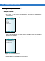


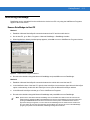
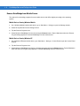

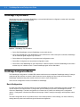

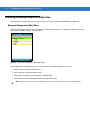

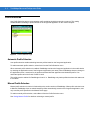
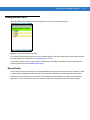
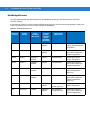
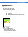
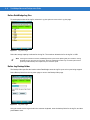
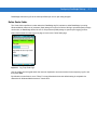


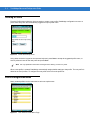
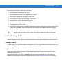
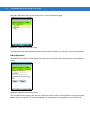
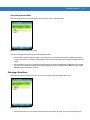
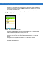

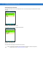

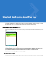


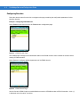
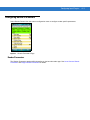

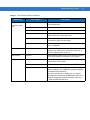

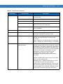
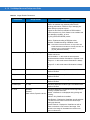
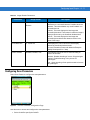
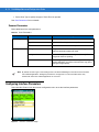
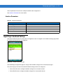
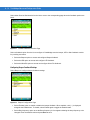

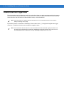

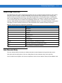

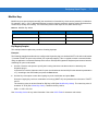
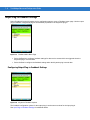
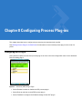
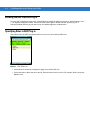
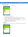
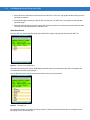
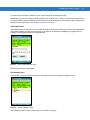
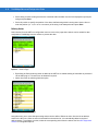
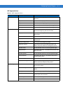

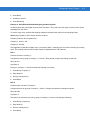


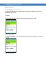


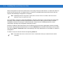
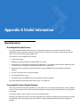
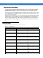


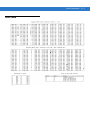


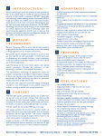


![Forms [packet] specific to Licensed Child Care](http://vs1.manualzilla.com/store/data/005750447_1-ace0dbf587046d14d311f9d21e5da3df-150x150.png)