1
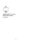
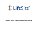
LifeSize® Video Communications Systems
Installation Guide
February 2011
LifeSize Room 220
LifeSize Team 220
LifeSize Express 220
LifeSize Video Communications Systems Installation Guide
Preparing for Installation
As you prepare to install your LifeSize video communications system, consider the physical conditions of
the room, compatibility with displays and your network configuration and settings. Related documentation
is available from lifesize.com/support.
Before You Install
If you are not using DHCP, you may need guidance from your network administrator to complete the initial
configuration. You will need to manually set an IP address, subnet mask, and default gateway for your
LifeSize system.
Network Bandwidth
Poor audio and video quality may result from insufficient bandwidth on your network. LifeSize recommends
that your network be capable of at least 1 Mb/s (incoming and outgoing) for a high definition video call.
During video calls with lower bandwidths, LifeSize systems automatically select the best resolution that
can be achieved with the available bandwidth.
Domain Name Service Server
If you intend to use domain addresses for placing calls, you must configure a Domain Name Service (DNS)
server, or use a Dynamic Host Configuration Protocol (DHCP) server that automatically sets a DNS server.
Room Configuration
The size, shape, layout and occupancy of the room dictate where you place your video conferencing
components. For example, in a multi-user conference room, place a LifeSize MicPod or LifeSize Phone at
the center of the group of participants.
You can lock the LifeSize codec with a secure loop to prevent physical removal of the device. For
assistance, contact your LifeSize Partner or LifeSize Customer Support.
WARNING
Avoid routing cables from the codec across foot-traffic areas. Tripping on
the cables can cause both personal injury and permanent damage to the
connectors in the cables and the codec itself.
The lighting in your environment affects image quality. The optimal lighting for LifeSize systems is 300 to
500 LUX. If light levels are too low, consider adding artificial light. Indirect light from shaded sources or
reflected light from pale walls often produces excellent results. Avoid the following:
•
direct sunlight on the subject matter, the background, or the camera lens
•
direct illumination of the subject matter and camera lens
•
colored lighting
•
harsh side lighting or strong light from above
2
LifeSize Video Communications Systems Installation Guide
System Components
Your package contains the following components:
•
One of the following audio components:
-
LifeSize Phone
-
LifeSize MicPod
•
LifeSize Camera 10x with power supply and standard 3-meter (9.8 foot) HDMI cable
•
Codec, stand (LifeSize Room 220 and LifeSize Team 220 only), and power supply
•
LifeSize remote control, including three AAA batteries
•
Quick reference card
•
Documentation CD
•
Standard cable kit
You can substitute cables of longer lengths with the following limits:
•
HDMI: 15 meters (49 feet)
•
Ethernet: 100 meters (328 feet)
Installing Your System
Before you install your system, read the LifeSize Safety and Regulatory Notices for important safety
information.
WARNING
Exercise care when connecting cables to the codec. Face the back of the
codec or ensure that all connectors are visible when connecting a cable to
the codec.
To install your LifeSize system, remove all components from the product packaging and place them in the
desired positions in your conference room or office.
WARNING
Do not place anything on top of or adjacent to the codec that can obstruct
air flow around the unit or generate heat. Doing so can cause the system
to overheat and reboot. Prolonged overheating can result in damage to
the codec. Make sure the room that houses the codec is properly
ventilated and temperature controlled.
3
LifeSize Video Communications Systems Installation Guide
Optional, for LifeSize Room 220 and LifeSize Team 220 only: Insert the codec into its stand by aligning the
pin holes at the base. Secure the codec by tightening the bolt on the bottom of the stand. Optional: Insert
the rubber feet on the bottom of the codec stand.
WARNING
Use the stand and bolt included in the product box. Using a stand and bolt
from another LifeSize model can damage the codec.
When using the stand, LifeSize recommends that you route at a minimum the thicker cables (DVI and
HDMI) through the plastic strain relief guide on the stand to enhance the stability of the codec and prevent
tipping. You can also remove the stand and lay the codec flat to improve stability.
Refer to the quick reference card included with your system for a visual depiction of the proper setup. The
numbers that appear on the quick reference card correspond to the following steps:
1. Open the battery compartment on the back of the remote control.
a. Before inserting the batteries, stretch each of the two straps across the outer battery slot closest to
to the battery.
b. Insert the two outer batteries, negative end (-) first against the spring, and press the positive (+)
end into place, thus trapping the cloth straps beneath the batteries.
c. Lay the longer cloth strap over both batteries and insert the center battery’s negative end against
the spring to trap the longer cloth strap beneath it. Press the positive end of the battery into place.
d. Lay the ends of the cloth straps over the center battery and install the cover.
2. To connect your LifeSize camera to the codec, insert the HDMI cable into the HD port on the camera
and plug the opposite end into the appropriate port on the codec:
-
LifeSize Room 220 and LifeSize Team 220: HD in 1
-
LifeSize Express 220: HD in
port
port
Insert the power adapter cable into the power port on the back of the camera and plug the power
adapter into a power outlet.
Optionally install the glare visor, using the notches on the lens barrel to guide the visor into its correct
position. Use the visor only if it is needed to improve the image in your environment.
CAUTION
Do not attempt to pick up the camera by the glare visor as it may pull
loose and subject the camera to damage or destruction from a fall.
4
LifeSize Video Communications Systems Installation Guide
3. Insert the HDMI display cable into the port on the rear of your display and the opposite end into the
Display 1 HD
port. (If you are using LifeSize Room 220 or LifeSize Team 220 with a stand, LifeSize
recommends you route this cable through the strain relief guide on the stand.) Insert the display power
cord into a power outlet. To connect a second display, refer to Configuring a Second Display.
NOTE
LifeSize Express 220: If you plan to use external speakers that are not built
into the display, connect the speakers to the port marked with the line out
symbol
on the back of the codec.
4. Insert the network cable into the network port marked with the LAN symbol
on the back of the
codec. Insert the opposite end of the network cable into a network port on the wall.
5. Do one of the following:
a. If you are using the LifeSize Phone for audio, insert the phone cable into the port marked with the
LAN symbol
on the underside of the phone.
NOTE
The exterior port marked with the
reserved for future use.
symbol on the LifeSize Phone is
Insert the opposite end of the phone cable into the port marked with the LifeSize Phone symbol
on the back of the codec. Ensure the cables are secured into the guides to avoid damage to
the cables.
NOTE
When the LifeSize Phone is connected to a LifeSize system, you cannot
configure it as a standalone speakerphone. Configure your system using the
system interface.
b. If you are using a single LifeSize MicPod for audio, insert the end of the cable from the
LifeSize MicPod into the microphone port marked with the microphone symbol on the back of
the codec. If you are using LifeSize Room 220 or LifeSize Team 220 with a stand, LifeSize
recommends you route this cable through the strain relief guide on the stand. Optionally, you can
add a LifeSize MicPod extension cable (not included) to the LifeSize MicPod. The extension cable
is 15 meters, 49.2 feet and LifeSize recommends using no more than one extension cable.
WARNING
LifeSize recommends that you use the cable strain relief clip included with
LifeSize MicPod as described in Attaching the LifeSize MicPod Strain
Relief Clip.
If you are using dual LifeSize MicPods for audio, refer to Configuring Dual LifeSize MicPods.
6. Insert the cord from the power adapter into the power outlet marked
on the back of the
codec (near the base). Insert one end of the power cord into the power adapter and the opposite end
into a power outlet on the wall. See Status Icons for more information about the state of the system as
it boots or as conditions change.
5
LifeSize Video Communications Systems Installation Guide
The LifeSize system starts and illuminates a blue LED on the front of the codec. The system status bar
at the bottom of the screen indicates system and network status. When the system is booting, status
also appears at the top of the REDIAL list to indicate the current state of the system.
The LifeSize system starts and illuminates a blue LED on the front of the codec.
The camera initializes the first time it is connected to a codec. This process takes approximately 90
seconds.
WARNING
Do not disturb or disconnect the devices during this time as you may
damage the system.
7. An Initial Configuration screen prompts you to configure the system. Refer to the LifeSize Video
Communications Systems User and Administrator Guide to complete the initial configuration. If the
initial configuration screen does not appear and the display is blank, refer to Troubleshooting
Installation Issues.
Placement Behind a Firewall
Refer to the LifeSize Video Communications Systems User and Administrator Guide for information about
configuring the system for firewall traversal.
Connecting a PSTN Phone Line
If you chose the Touch Tone option for the Voice Dialing preference during the initial configuration of
LifeSize Room 220 or LifeSize Team 220, ensure that you connect an RJ-11 PSTN phone cord to the
PSTN phone port labeled
on the LifeSize codec and the other end to a phone jack on the wall.
Supported Display Types and Resolutions
LifeSize video systems connect to HD displays (720p minimum), including:
•
plasma, LCD, and LED flat panel displays
•
large screen rear projection TV displays (720p/1080p displays)
•
front projection displays
•
rear projector A/V room configurations
Supported display resolutions include the following:
Display 1
1280 x 720p60
1280 x 768p60
1920 x 1080p30
1920 x 1080i60
Display 2
1280 x 720p60
1280 x 768p60 (LifeSize Room 220 and LifeSize Team 220 only)
1920 x 1080p30
1920 x 1080i60
6
LifeSize Video Communications Systems Installation Guide
The primary output defaults to 720p60 and will work with any 720p HD display. Learn how to change the
resolution for 1080 HD displays in Changing Display Resolution.
LifeSize recommends using a dual display configuration for presentations.
NOTE
The Display 1 Resolution and Display 2 Resolution preferences in
Appearance : Displays default to Auto if you select an option for these
preferences that the connected display does not support. If the resolutions are
not the same, Display 2 will be limited to displaying presentations and will not
be able to mirror the primary display or display calls. For more information,
see Configuring a Second Display.
Changing Display Resolution
The primary output defaults to 720p60 and will work with any 720p HD display.
To change the display resolution, navigate to Administrator Preferences : Appearance : Displays and
choose Display 1 Resolution. You can change the resolution to 1920x1080i60 or 1920x1080p30 and it
will work with most 1080 HD displays. Some 1080p displays will not work with 1080p30 mode and the
display may be blank. In this case you must configure the display resolution from either the LifeSize Phone
(refer to Blank or Distorted Display) or from the web administration interface. LifeSize recommends that
before you change the display resolution to 1920x1080p30, ensure that you can access the Display 1
Resolution preference using one of these methods.
Configuring a Second Display
To connect a second display, insert the video display cable into the port on the rear of your display and the
opposite end into the Display 2 HD 2 port on the codec. (If you are using LifeSize Room 220 or
LifeSize Team 220 with a stand, LifeSize recommends you route this cable through the strain relief guide
on the stand.) Attach the display power cord to a power outlet. By default, the second display is blank.
Navigate to Appearance : Layout and choose Display 2 Layout, which by default is set to None.
•
Choose Presentations + DVI-I Input to display presentations (local and remote) during a call that is
sending or receiving a presentation. When not in a call, background image appears in the display.
•
Choose Calls + Presentations + DVI-I Input to display:
•
-
video images from video calls
-
presentations (local and remote) in a call that is sending or receiving a presentation
-
background image when not in a call
Choose Simulcast Calls + DVI-I Input to show the same output on Display 2 as shown on Display 1
during calls.
7
LifeSize Video Communications Systems Installation Guide
If you use a VGA projector as Display 2, navigate to Administrator Preferences : Appearance :
Displays and choose Display 2 Resolution. Configure its resolution to 1280 x 768 to match the default
HD configuration of Display 1.
NOTE
To use the Calls + Presentations + DVI-I Input or Simulcast Calls + DVI-I Input
options, you must set Display 1 and Display 2 to the same resolution;
otherwise, you will see a warning message and this option will be forced to
Presentations + DVI-I Input.
The following conditions apply when using two displays with LifeSize Express 220:
•
The presentation icon that appears on screen during a call to indicate that a near or far end
presentation is in progress appears in Display 1 above. For a presentation sent from a far end
participant, the receiving presentation icon
appears in the upper-left corner of Display 1; for a
presentation sent from the near end, the sending presentation icon
appears in the lower-right
corner of Display 1.
•
If you choose Calls + Presentations + DVI-I Input or Simulcast Calls + DVI-I Input for the Display 2
Layout preference, the following status icons and information do not appear in video images in the
second display during calls:
-
caller ID information and call type (voice or video) icons
-
camera selection icons
NOTE
Selecting a camera to control by pressing the near/far camera button on the
remote control during a call shows no indication of which participant’s camera
is selected if the participant’s video image appears only in the second display.
-
encryption icons
-
mute icon
•
Only presentation video or DVI-I input is supported for Display 2. Background image and color
preferences that appear in Appearance : Backgrounds are available for Display 1 only. The user
interface appears only in Display 1.
•
When the logo screen saver is active on the primary display, the second display shows the background
image instead of the screen saver.
8
LifeSize Video Communications Systems Installation Guide
Optional Peripherals
You can connect the following optional peripherals to enhance your LifeSize system:
Peripheral
Supported Systems
Usage
Analog phone line in
LifeSize Room 220
For PSTN connectivity.
LifeSize Team 220
Audio In (Line In) 1
Line In - All systems
Audio In (Line In) 2
Line In 2 - LifeSize Room 220 and
LifeSize Team 220
Audio Out (Line Out)
All systems
With an external line level audio input.
With external line level output speakers that are not
built into display 1 or with a headset (left plus right).
Warning: Excessive sound pressure from earphones
and headphones can cause hearing loss.
Auxiliary Video In
LifeSize Room 220
For inputting component, S-video or composite
video. Only one can be used at a time. A component
source always takes precedence. If S-video and
composite sources are both plugged in, the S-video
source takes precedence. Auxiliary Video In is
typically used to connect a DVD or VCR to share
standard video content with the far end during a
presentation or to view the content locally.
DVI-I In (PC in)
All systems
With devices and laptops for presentations or to
share PC data. Accepts both digital video and VGA
analog signals with the proper adapter cable. For
devices and PCs with VGA output, LifeSize includes
a DVI-A to VGA cable. An HDMI source can be used
with an adapter.
HD Camera
LifeSize Room 220
With a LifeSize firewire camera.
LifeSize Team 220
HD in 2
LifeSize Room 220
With a second LifeSize HDMI camera.
Networker
All systems
With LifeSize Networker.
Note: On LifeSize Express 220, this port is also
marked with the LifeSize Phone symbol
and
can be used with either LifeSize Phone or
LifeSize Networker.
Serial RS-232
LifeSize Room 220
With supported third-party cameras using VISCA
control or for automation control with Crestron or
AMX controllers.
USB port
All systems
Used for USB to serial adapters.
Configuring Dual LifeSize MicPods
In a dual LifeSize MicPod configuration, you use a combination of two LifeSize MicPods, one splitter cable,
and extension cables in large rooms for maximum omnidirectional audio coverage.
You cannot use multiple splitters to connect to more than two LifeSize MicPods; however, you can use
variations on three configurations of extension cables:
9
LifeSize Video Communications Systems Installation Guide
•
If you connect the male end of the splitter directly to the codec, you can use none, or one extension
cable to connect a LifeSize MicPod to each of the female ends of the splitter.
•
If you use one extension cable to connect the codec to the splitter, you can use none, or one extension
cable to connect a LifeSize MicPod to each of the female ends of the splitter.
•
If you use two extension cables to connect the codec to the splitter, you must connect both
LifeSize MicPods directly to the female ends of the splitter.
WARNING
LifeSize recommends that you use the cable strain relief clip included in
the LifeSize MicPod product box as described in Attaching the
LifeSize MicPod Strain Relief Clip to avoid personal injury or damage to
the unit.
A LifeSize codec detects any splitter or cable attached to the microphone input of the codec as a
LifeSize MicPod. If a LifeSize MicPod is not attached to the extension or splitter cable and the microphone
input is selected as the active microphone, no audio is available. The
indicator does not appear in the
status bar and the Active Microphone field in the System Information page reports Microphone In as the
active microphone.
Attaching the LifeSize MicPod Strain Relief Clip
If the LifeSize MicPod is installed in an area where you could pull or trip over the cord, LifeSize
recommends using the strain relief clip included with your LifeSize MicPod to reduce the chance of
disconnecting or damaging the plug or the system codec.
Ensure that the codec surface is clean (free of dirt, dust, oil, and other residues) and dry. The adhesive
tape on the strain relief clip is intended for a single use. Attach the strain relief clip to the codec and route
the LifeSize MicPod cable through the strain relief clip as shown in the following illustration.
To obtain a replacement strain relief clip, contact your LifeSize Partner.
10
LifeSize Video Communications Systems Installation Guide
Verifying Your Installation
The LifeSize Video Communications Systems User and Administrator Guide explains how to place a test
call to verify your installation. The guide also describes additional configuration steps if your environment
uses any of the following:
•
Network Address Translation (NAT)
•
a firewall
•
H.323 gatekeepers
•
Session Initiation Protocol (SIP)
•
other network security systems
Troubleshooting Installation Issues
Installation issues that you may encounter with your LifeSize system typically involve improperly
connected cables, network bandwidth or connectivity. For more information about troubleshooting issues
you may encounter with LifeSize systems, refer to the LifeSize Video Communications Systems User and
Administrator Guide.
Loose Cables
Improperly connected or loose cables are common causes of problems with hardware units. When
investigating a system problem, inspect the external controls and cable connections. Ensure that
connections are correct and secure and that nothing is obstructing the cables.
Blank or Distorted Display
If your screen image is distorted and unusable or the display is blank, you can configure the display from
the web administration interface. Follow these steps:
1. Enter the IP address of your system in a browser.
NOTE
Ignore any warnings on security certificates.
2. Navigate to Preferences : Appearance : Displays
3. For Display 1 Resolution, select Auto.
4. Select Save Changes and Log out.
11
LifeSize Video Communications Systems Installation Guide
No Power
To troubleshoot a power problem, complete the following steps:
1. Disconnect the power supply unit (PSU) from the LifeSize codec and the AC source.
2. Plug a working appliance into the AC source to determine if the source is functioning.
3. If the AC source works, plug the PSU into the AC source, but do not connect the PSU to the LifeSize
codec. If the green LED on the PSU illuminates, the PSU is probably functioning.
4. Disconnect the PSU from the AC source. Connect the PSU to the LifeSize codec. Reconnect the PSU
to the AC source. If the LifeSize codec fails to boot and the green LED on the PSU dims, the codec
may be the source of the problem.
IP Address Displays Invalid Value
If the IP address that appears at the top of the main screen displays an invalid value after you complete the
initial configuration, one of the following conditions may exist:
Condition
Resolution
The unit is configured to obtain an address using
DHCP and no DHCP server is available.
Verify that the unit is plugged into a network that has a
DHCP server present.
Note: The DHCP client self-assigns an address in
the 169.254 class B network and the red network
symbol
appears in the status bar on the main
screen.
Faulty Ethernet cable connection.
Replace the Ethernet cable with a high quality cable.
The unit is configured to use a static IP address, but
no IP address has been entered.
Identify and enter the necessary IP information.
Network connection is unavailable.
Inspect your network connection.
A red network symbol
on the main screen.
appears in the status bar
Camera Issues
Video from the camera appears in a small window on the main screen of the user interface above the
Redial list. If no video from the camera appears, do the following:
•
Ensure that the camera is properly connected to the LifeSize codec as described in Installing Your
System.
•
Verify that the blue LED on the front of the camera is lit and not blinking.
•
From the main screen of the user interface, press
to access the System Menu. Press
to
access page 2 of the System Information page. Ensure that the status of the camera is Ready.
•
Ensure that the primary input is set to the high definition camera. Press
. If Primary Input : HD
Camera does not appear at the top of the screen, press
to display the Primary Input selection
dialog. Use the arrow keys on the remote control to select the appropriate high definition camera and
press OK.
12
LifeSize Video Communications Systems Installation Guide
Improving a Dim Image
Adjust the HD Camera Brightness preference in Diagnostics : High Definition Camera. You can also
add a light source to improve the subject’s illumination. Read more at Room Configuration.
Attached Video Input Device Not Working
When you connect a video input device that has capabilities not supported by a LifeSize system, the status
Out of range appears on the System Information page for that input. The device may be in a mode that
the codec does not support. If changing the mode does not help, the device is not supported.
Status Icons
The following table identifies the icons that can appear in the system status bar.
Icon
Condition
Indicates that the communication subsystem is initializing. If this icon reappears after the
system has booted, a problem has occurred. Reboot the system.
Indicates that the system is initializing. When the system is initializing, functionality on the main
screen is disabled and no entries appear in the REDIAL list. This icon also appears when a new
device is connected to the system after the system boots and disappears when the device is
ready. If the icon persists, a problem has occurred and rebooting the system is necessary.
Indicates that the connected phone has been detected and the phone is initializing. If the icon
persists, a problem has occurred and rebooting the system is necessary.
Indicates that the system does not have an active microphone. Check the device’s connections
and then check the option you selected for the Active Microphone preference.
Network Status
Identifies the network status, as follows:
connected (green indicator)
in progress (yellow indicator)
disconnected (red indicator)
Indicates the status of the registration process with H.323 gatekeeper.
The yellow H.323 icon appears when your LifeSize system is trying to register with the
gatekeeper. If the registration fails, the red H.323 icon appears. If the system is registered to a
gatekeeper, the system shows its status.
Indicates the status of the registration process with the SIP server.
The yellow SIP icon appears when your LifeSize system is trying to register with the SIP server.
If the registration fails, the red SIP icon appears.
System
Overheating
The yellow indicator warns you when the system temperature is above normal operating
temperature. The codec adjusts fan speed automatically to cool itself.
The red indicator warns that the system is overheated and approaching the maximum allowed
operating temperature where it will automatically reboot.
Warning: Temperatures that require the codec to reboot can permanently damage codec
components. Ensure that the room that houses the codec is properly ventilated and
temperature controlled.
13
February 2011
Copyright Notice
©2005 – 2011 Logitech, and its licensors. All rights reserved.
LifeSize Communications, a division of Logitech, has made every effort to ensure that the information contained in this
document is accurate and reliable, but assumes no responsibility for errors or omissions. Information in this document
is subject to change without notice. Companies, names, and data used in examples herein are fictitious unless noted.
This document contains copyrighted and proprietary information which is protected by United States copyright laws
and international treaty provisions. No part of the document may be reproduced or transmitted, in any form or by any
means, electronic or mechanical, for any purpose, without the express written permission from LifeSize
Communications.
Trademark Acknowledgments
LifeSize, the LifeSize logo and other LifeSize marks, are owned by Logitech and may be registered. All other
trademarks are the property of their respective owners.
Patent Notice
For patents covering LifeSize® products, refer to lifesize.com/support/legal.
Contacting Technical Services
If you have questions, concerns, or need assistance, contact your LifeSize Partner.
Contacting Technical Services
LifeSize Communications welcomes your comments regarding our products and services. If you have feedback about
this or any LifeSize product, please send it to [email protected]. Refer to lifesize.com/support for additional ways
to contact LifeSize Technical Services.